Efficiency Enhancement Using Various Types
Defected Ground Structures for Micro strip
Patch Antenna
Adil Siddiqui1, Konark Yadav2, and Smrity Dwivedi3
1& 2Student, ECE Department, The LNM Institute Of Information Technology, Jaipur, India 3Assistant Professor, ECE Department, The LNM Institute Of Information Technology, Jaipur, India
Abstract: This present paper investigates how the defects of different shapes and sizes in the ground of a Micro strip Patch Antenna improves its technical parameters like VSWR, Return Loss, efficiency etc. This has been done by examining and experimenting by cutting different shapes of defects in the ground of a Micro strip Patch Antenna. Authors are presenting the Micro strip Antenna for Wi-Fi frequency in this paper. The performance and advantages of Micro strip antenna such as low cost, low profile, low weight made them perfect choice for communication systems engineers.
Keywords: Micro Strip Patch Antenna (MPA), Defected Ground Structure (DGS), HFSS I. INTRODUCTION
A micro strip antenna is a narrowband, wide-beam antenna fabricated by etching the antenna element pattern in metal trace bonded to an insulating dielectric substrate, such as a printed circuit board, with a continuous metal layer bonded to the opposite side of the substrate which forms a ground plane. Common micro strip antenna shapes are square, rectangular, circular and elliptical, but any continuous shape is possible [1-4].
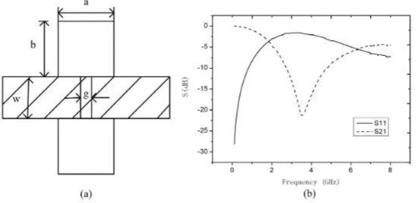
DGS is an etched periodic or non-periodic cascaded configuration defect in ground of a planar transmission line (e.g., micro strip, coplanar and conductor backed coplanar wave guide) which disturbs the shield current distribution in the ground plane cause of the defect in the ground. This disturbance will change characteristics of a transmission line such as line capacitance and inductance. In a word, any defect etched in the ground plane of the micro strip can give rise to increasing effective capacitance and inductance [4-8].
Table 1. Parameters and their Values
Sr. No Description Value/Mm
1 Antenna Length 50
2 Antenna Width 45
3 Size of Slot 5
4 Substrate Thickness, h 0
5 Feed Size 3.2
II. ANTENNA DESIGN
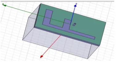
Both MPA and proposed antenna are designed on Rogers RT/Duroid 5880 (TM) substrate with thickness (hs) of 3.2 mm, having relative permittivity (ɛr) of 2.2. The patch has dimensions of 20 x 15
mm with height (hp) of 3.2 mm. The ground has dimensions of 50 x 45 mm with height (hg) of 3.2
mm. The circular feeding with radius of 1.6 mm. The complete structure of simple MPA is shown in figure 2.
Figure 2. Structure of Simple Micro strip Patch Antenna
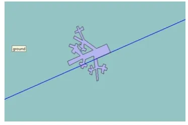
In order to improve the Bandwidth and Return Loss, ground is defected with different slots like, F - shaped, A - shaped, Tree shaped. Also these slots made on ground helps in reduction of overall weight and size of proposed antenna.
Figure 5. Structure of Tree-shaped DGS Antenna
The proposed antenna has a resonating frequency of 2.4 GHz. The resonant frequency is also known as center-frequency, is selected as one at which the return loss is minimum.
For a specific resonant frequency (fr) and dielectric constant of substrate (ɛr) the width W, the length
(L) of patch of MPA are expressed as follow:
Where, F/m
1.26 × H/m
Where is the free-space velocity of light
= L + 2ΔL
Where, Leff and ∆L are the effective and extended Length of patch and are expressed as
Where, is the effective dielectric constant of substrate and is expressed as:
+
Similar results for finite and infinite ground plane can be obtained if the size of the ground plane is greater than the patch dimensions by approximately six times the substrate thickness all around the periphery. Hence, for this design, the ground plane dimensions would be given as
Lg = 6h + L
Wg = 6h + W
Where 'h' is the height of substrate and Lg , Wg are length and width of ground plane respectively. In
order to improve the Bandwidth and Return loss, ground is defected with F-Shape, A-Shape, and Tree-Shape slot. Also this slot made on ground helps in the reduction of overall weight and size of proposed antenna.
III. RESULT AND DISCUSSION
A) Return Loss (S11) and Bandwidth
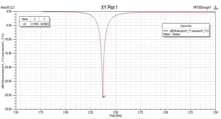
It is evident from Fig. 5-7, that when F-shaped, A-shaped, Tree-shaped defect in ground plane is introduced, the proposed antenna resonates at resonant frequency fr = 2.3700 GHz. A very good return loss of -32.7662 dB at fr = 2.3700 GHz is obtained for F-slot DGS, -32.7662 dB at fr = 2.3700 GHz for A-slot DGS, -32.9823 dB at fr = 2.3700 GHz for Tree-slot DGS. At this resonant frequency, it gives a maximum bandwidth of 100 MHz for Tree-slot DGS, maximum bandwidth of 120 MHz for A-slot DGS, and maximum bandwidth of 100 MHz for F-slot DGS.
Fig 5. Return Loss for F-slot DGS Antenna
Fig 7. Return Loss for Tree-shape DGS Antenna
B) VSWR
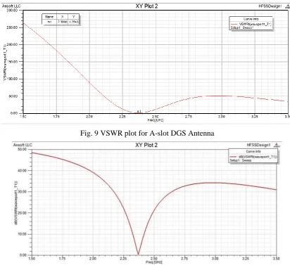
Fig. 8-10 shows VSWR plot of the proposed antennas. At frequency of 2.3700 GHz, the VSWR for A-slot DGS is 1.6968, the VSWR for F-slot DGS is 1.2643, and the VSWR for Tree-slot DGS is 1.5784. As the value of VSWR is approximately equal to 1 at resonant frequency (fr), proposed antenna results in perfect impedance matching.
Fig. 9 VSWR plot for A-slot DGS Antenna
Fig. 10 VSWR plot for Tree-slot DGS Antenna
IV. CONCLUSION
These new patch antennas with Defected Ground Structures (DGS) demonstrate properties: improved returning loss, VSWR bandwidth, gain of the antenna as compared to the conventional antenna. These fundamental parameters are modeled with the equations and estimated with HFSS software and measured the result of the antenna designing with DGS with network analyzer. The effects of introducing DGS into the ground plane of the antenna have been successfully investigated. The antennas operate well at their corresponding frequencies of operations. The rectangular patch antenna designed with A-shaped, F-shaped, Tree-shaped structures DGS shows gain of 5.36 dB for A-shaped, 5.37 dB for F-shaped, and 3.80 dB for Tree-shaped . Moreover, the radiating patch area is smaller as compared to the conventional antenna without DGS. So, this antenna design with DGS not only improve the parameters of the antenna without DGS but also can provide a smaller size of radiating patches, which will cause an overall reduction in antenna size.
Conflict of interest: I declare that I have no conflict of interest. All the statements given in this paper, are original and not a single statement is copied from anywhere.
REFERENCES
[1] Singh Gurpreet, Rajni, Momi Ranjit Singh, "Micro strip Patch Antenna with Defected Ground Structure for Bandwidth Enhancement", International Journal of Computer Applications, Volume 73-No.9
[2] Guha Debatosh, Biswas Manotosh, Antar M.M. Yahia, "Micro strip Patch Antenna With Defected Ground Structure for Cross Polarization Suppression ", IEEE antenna and wireless propagation letters, volume-4, 2005.
[3] Balanis C. A., “Antenna Theory and Analysis,” Third Edition, John Wiley & Sons, 2005
[4] Arya Ashwini K. , Kartikeyan M. V., Patnaik A ., “Defected Ground Structure in the perspective of Microstrip antenna,” Frequenz, Vol.64, Issue5-6, pp.79-84 , Oct 2010
[5] Geng, Jun-Ping, Li Jiajing, Jin Rong-Hong, Ye Sheng, Liang Xianling, and Li Minzhu. "The development of curved microstrip antenna with defected ground structure." Progress In Electromagnetics Research 98 (2009): 53-73.
[6] Weng L. H., Guo Y. C., Shi X.W., Chen X. Q.,“ An overview on defected ground structure,” Progress in electromagnetic Research B, Vol.7, pp.173-189, July 2008
[7] Lin, Xian-Chang, and Wang Ling-Teng. "A wideband CPW-fed patch antenna with defective ground plane." In Antennas and Propagation Society International Symposium, 2004. IEEE, vol. 4, pp. 3717-3720. IEEE, 2004