Design of Triangular Patch Antenna with
reduced RCS for Stealth Applications using
Bionics
S. Jaya Sree1, K.T.P.S.Kumar2, P.Devi3, R.Sowmya4, P.L. Sai Babu5, B. Mohana Rajesh6
B. Tech Student, Department of Electronics and Communication Engineering, LIET, JNTUK, India1
Associate Professor, Department of Electronics and Communication Engineering, LIET, JNTUK, India2
Assistant Professor, Department of Electronics and Communication Engineering, LIET, JNTUK, India3
B. Tech Student, Department of Electronics and Communication Engineering, LIET, JNTUK, India4
B. Tech Student, Department of Electronics and Communication Engineering, LIET, JNTUK, India5
B. Tech Student, Department of Electronics and Communication Engineering, LIET, JNTUK, India6
ABSTRACT: In this paper Bionics principle is applied to the proposed triangular antenna to show the antenna radar cross section (RCS) reduction by the use of a model insect tentacle antenna . Bionics is the study of mechanical systems that function like living organisms or parts of living organisms. To authenticate this method, a novel triangular micro strip patch antenna with reduced RCS is proposed and simulated for stealth applications. Mono static RCS and Bi-static RCS of an insect tentacle antenna (ITA) of triangular shape is proposed and simulated.. In this paper we have taken the Flame retarded substrate (FR4) which is made up of epoxy resin component, which is a very smooth substrate and is very cheaper to manufacture and gives better return loss. The substrate FR4 Epoxy used in this have a dielectric constant of 4.4. The results shown that the performance of the proposed triangular antenna has lower RCS and favourable radiation performances.
KEYWORDS: Micro strip patch antenna, Mono static RCS, Bi-static RCS ,Return loss, Bionics, Stealth Technology.
I. INTRODUCTION
and good radiation characteristics. Design and manufacture of UWB antennas is among the most critical problems nowadays as it opens a promising door to the future of wireless communications and military applications such as ultra wide band (UWB) radars, military high-data-rate wireless communications, and so on. An UWB antenna should provide a gain and impedance bandwidth from 3.1 to 10.6 GHz. However, with the development of target identification technology, the design of UWB antennas with low RCS becomes crucial to the survivability of the antenna platforms, yet few publications on the RCS reduction of UWB antennas have been published. To solve this problem, an RCS reduction technique using bionics principle is first proposed in this letter.For this, we use a suitable UWB antenna which should be capable of operating over an ultra wide bandwidth as allocated by the Federal Communications Commission. They usually radiate different frequency components from different parts of the antenna, which distorts and stretches out the radiated waveform. And now, we apply this method to the Stealth technology, which aims to control the characteristic signal of the target to make it difficult to be detected and attacked in the low observable platform. Many military platforms are required to exhibit a low RCS in order to avoid detection by radar. The goal of stealth technology is to make an airplane invisible to radar. The two different ways to create invisibility is, the airplane can be shaped so that any radar signals it reflects that are reflected away from the radar equipment and also the airplane can be covered in materials that absorb radar signals. Such that a stealth aircraft is made up of completely flat surfaces and very sharp edges to reflect less signals to overcome the threat. For this process, we are using Bionics technology, it is the study of mechanical systems that functions like parts of the living organisms. In this project Bionics principle is applied to antenna radar cross section (RCS) reduction. Mono static RCS of an insect tentacle antenna (ITA) terminated with three different loads are studied and compared with that of a triangular patch antenna. So that the wings of an organism like insect, which is used to protect itself from threat. Therefore, by using this technique we can reduce the reflected signals away from the threat. This results shows that, compared to the reference antenna, the novel bionic antenna has lower RCS and favorable radiation performances. Hence, applying bionics principle to antenna for RCS reduction is feasible, which will serve as a good area for the future design of antennas with a requirement of RCS control.
II. RELATED WORK BASED ON RCS, STEALTH TECHNOLOGY AND BIONICS
Radar cross section (RCS) represents the ability of targets in capturing and scattering the power of the signal. Antenna scattering is the main contribution to the total radar cross section (RCS) of low observable platforms. An antenna is a special scattered whose scattering is related with its feed termination impedance, which handicaps the design of antennas with low RCS and good radiation characteristics
Stealth technology aims to control the characteristic signal of the target to make it difficult to be detected and attacked in the low observable platform. Many military platforms are required to exhibit a low RCS in order to avoid detection by radar. The radar cross section (RCS) of sensitive targets has been reduced considerably in the recent years. As to low observable platform, one of the major contributing sources of target RCS is the scattering due to onboard antennas, so the control of the RCS of the antenna gains more and more interest.
Bionics is the application of biological methods and systems found in nature to the study and design of engineering systems and modern technology. The word bionic was coined by Jack E. Steele in 1958, possibly originating from the technical term bion (pronounced BEE-on; from Ancient Greek: βίος), meaning 'unit of life' and the suffix -ic, meaning 'like' or 'in the manner of', hence 'like life'. It is a term which refers to the flow of concepts from biology to engineering and vice versa. Hence, there are two slightly different points of view regarding the meaning of the word. In medicine, bionics means the replacement or enhancement of organs or other body parts by mechanical versions.
III. ANTENNA GEOMETRY
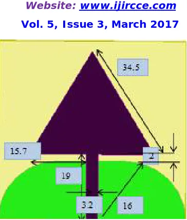
Fig1. Reference antenna
The triangular patch of the proposed antenna is designed totally different rather than rectangular or circular patches. In order to improve the RCS, a new triangular patch of small effective area is innovated in this design. By doing so, the maximum detection range of the target decreases, hence the RCS will become more efficient. In this paper we have taken the Flame retarded substrate (FR4) which is made up of epoxy resin component, which is a very smooth substrate and is very cheaper to manufacture and gives better return loss.
IV. PERFORMANCE AND CHARACTERISTICS
All the simulations in this work are obtained with the help of HFSS software. The measured value of proposed antenna return loss is -62.5 dB at 10GHz. The return loss in dB with respect to frequency at 10GHz for the proposed antenna proves that it can be used for stealth applications at 10GHz. Unlike calculating the return loss for patches differently, here the return loss is calculated for entire micro strip patch antenna. In order to get the efficient return loss, the substrate FR4 was used in this antenna design as it had dielectric constant of 4.4 with a tangent loss of 0.02. The major modification done in this antenna was applying bionics principle to the antenna in order to reduce the radar cross.
Table 1:
Parameters and their values
S.NO PARAMETER REFERENCE
ANTENNA
PROPOSED ANTENNA
1. Return loss -25 -62.5
2. Monostatic RCS -6 -50
V.RESULTS AND ITS DISCUSSION
This section is about referring the calculation and parametric study of refereed and proposed antenna simulation. The proposed antenna has been analysed by simulation and it is compared with the reference antenna. The characteristics that are compared in this work are return loss and radiation pattern. Fig 2 shows the graph between the return loss and the frequency. In this figure we have a return loss -62.5dB at 10GHz frequency
FREQUENCY VERSUS RETURN LOSS
Fig. 2. Graph of Return loss versus Frequency.
Fig 2. Shows graph between return loss and frequency. In this figure we have return loss -25dB at operating frequency 10GHz for reference antenna.
PROPOSED ANTENNA
FREQUENCY VERSUS RETURN LOSS FOR PROPOSED ANTENNA
Fig.4 Frequency versus return loss graph for proposed antenna.
This figure shows that frequency versus impedance. For proposed antenna, we got impedance 50Ω operating frequency at 6 GHz in high frequency simulation software (HFSS).
Fig.7Bi-static RCS for reference antenna Fig.8 Bi-staticRCS for proposed antenna
EXTENDED DESIGN
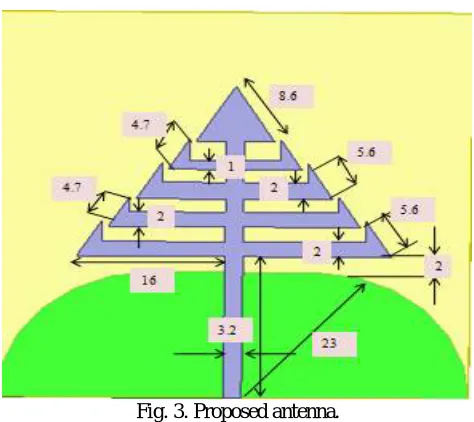
Fig.9 Extended design
We can design the proposed triangular design in the above manner also, where the return loss is expected to be lesser than the reference antenna and the monostatic RCS, bi-static RCS graphs will also have been observed
will be invisible to the radar. These are mostly used for military applications. The proposed antenna having radiation characteristics with a return loss of -19dB at 5GHz frequency. Its compactness, good frequency versus losses response will definitely help this designed antenna to be applicable for stealth applications
REFERENCES
[1.] Knott, E. F., et al., Radar Cross Section, 2nd edition, SciTech, Raleigh, NC, 2004.
[2.] Pozar, D., “Radiation and scattering from a micro strip patch on a uniaxial substrate,” IEEE Trans. Antennas Propag., Vol. 35, No. 6, 613–621,
1987.
[3.] H. Oraizi and A. Abdolali, “Ultra wide band RCS optimization of multilayered cylindrical structures for arbitrarily polarized incident plane
waves,” Progress In Electromagnetics Research, PIER 78, 129-157,2008.
[4.] Q.-R. Zheng, Y.-M. Yan, X.-Y. Cao and N.-C. Yuan, “High impedance ground plane (HIGP) incorporated with resistance for radar cross
section (RCS) reduction of antenna,” Progress In Electromagnetics Research, PIER 84, 307̢319, 2008.
[5.] E. F. Knott, J. F. Shaeffer, M. T. Tuley, “Radar CrossSections”, SciTech Publishing Inc., 2nd ed., 2004.
[6.] Jiang Wen, Gong Shu-xi, Hong Tao, Wang Xing,“Fan-shaped antenna with low RCS for ultra-wideband application,” Acta Electronica Sinica,
Vol. 38, No. 9, 2162-2165, 2010.
[7.] Hai-yang Xu, Hou Zhang, Gui-yuan Li, Qi-bo Xu, etc. “An ultra-wideband fractal slot antenna with low backscattering cross section,”
Microwave and Technology Letters, Vol. 53, No. 5, 1150-1154, 2011.
[8.] Hai-yang Xu, Hou Zhang,, Ke Lu and Xian-feng Zeng. “A holly-leaf-shaped monopole antenna with low RCS for UWB application,” Progress
In Electromagnetics Research, Vol. 117, 35̢50, 2011.
[9.] Horng-Dean Chen. “Broadband CPW-fed Square slot antennas with a widened tuning stub,” IEEE.
[10.] Jianxin Liang, Choo C.Chiau, Xiaodong Chen, etc “Study of a printed circular disc monopole antenna for UWB systems,” IEEE Transaction
on antennas propagation, Vol. 53, No. 11, 3500-3504, 2005.
[11.] E.A. Soliman, S. Brebels, P. Delmotte, G.A.E. Vandenbosch and E. Beyne. “Bow-tie slot antenna fed by CPW,” Electronics Letters, Vol. 35,
No. 7, 514-515,1999.
[12.] C.-Y. Huang and W.-C- Hsia: ‘Planar elliptical antenna for ultra-wideband communications’, Electronics Letters, 2005, 41.
[13.] Hu S, Chen H, and Law C L, “Backscattering cross section of ultra-wideband antennas,” IEEE Antennas and Wireless Propagation Letter, Vol.
6, 70–73, 2007.
[14.] Liang, J., C. Chiau, X. Chen, and C. Parini, “Study of a printed circular disc monopole antenna for UWB s systems,” IEEE Trans. Antennas
Propag., Vol. 53, No. 11, 3500–3504, 2005.
[15.] Hu, S., H. Chen, C. Law, Z. Shen, L. Zhu, W. Zhang, and W. Dou, “Backscattering cross section of ultra wideband antennas,” IEEE Antennas
and Wireless Propagation Letters, Vol. 6, 70–73, 2007.
[16.] Liu, Y., D.-M. Fu, and S. X. Gong, “A novel model for analyzing the radar cross section of microstrip antenna,” Journal of Electromagnetic