How Rapid is Rapid Prototyping? Analysis of ESPADON
Programme Results
Bob K. Madahar
BAE SYSTEMS Advanced Technology Centre, West Hanningfield Road, Gt. Baddow, Chelmsford CM2 8HN, UK
Email:[email protected]
Ian D. Alston
BAE SYSTEMS Advanced Technology Centre, West Hanningfield Road, Gt. Baddow, Chelmsford CM2 8HN, UK
Email:[email protected]
Denis Aulagnier
Thales Airborne Systems, 10 avenue de la 1`ere DFL, 29283 Brest Cedex, France
Email:[email protected]
Hans Schurer
Thales Naval Nederland, Zuidelijke Havenweg 40, P.O. Box 42, 7550 GD Hengelo, The Netherlands
Email:[email protected]
Mark Thomas
Thales Underwater Systems, Dolphin House, Ashurst Drive, Bird Hall Lane, Cheadle Heath, Stockport, Cheshire, SK3 0XB, UK
Email:[email protected]
Brigitte Saget
MBDA France, 20-22 rue Grange Dame Rose, BP 150, 78141 Velizy-Villacoublay Cedex, France
Email:[email protected]
Received 14 March 2002 and in revised form 9 October 2002
New methodologies, engineering processes, and support environments are beginning to emerge for embedded signal processing systems. The main objectives are to enable defence industry to field state-of-the-art products in less time and with lower costs, including retrofits and upgrades, based predominately on commercial offthe shelf (COTS) components and the model-year concept. One of the cornerstones of the new methodologies is the concept of rapid prototyping. This is the ability to rapidly and seamlessly move from functional design to the architectural design to the implementation, through automatic code generation tools, onto real-time COTS test beds. In this paper, we try to quantify the term “rapid” and provide results, the metrics, from two independent benchmarks, a radar and sonar beamforming application subset. The metrics show that the rapid prototyping process may be sixteen times faster than a conventional process.
Keywords and phrases:rapid prototyping, COTS, model year, beamformer, EDA tools, heterogeneous platform, FPGA.
1. INTRODUCTION
The trinational European EUCLID/Eurofinder defence project called ESPADON (environment for signal process-ing application development and rapid prototypprocess-ing) com-pleted in September 2001 [1]. The ESPADON consortium comprised Thales and MBDA from France, Thales Naval Nederland, BAE SYSTEMS, and Thales Underwater Systems
From system development
Plan SP development
R
equir
ements
Risk
R
eg
ist
er
De
ve
lopment
Plan
Specification
Functional design
Architectural design
Implementation
System review To system development Key: Process Artefact Development control
Process flow Information flow Figure1: Iterative development process.
prototyping. The latter two concepts are an integral part of the model-year concept adopted by ESPADON and devel-oped under the US RASSP programme [2].
A brief summary of these techniques and developments within ESPADON,1in the context of rapid prototyping (RP), is presented below.
1.1. The methodology
A risk-driven iterative development process has been iden-tified. This is shown in abstract form inFigure 1and is un-derpinned by the following 5-key processes stemming from the methodology MCSE (m´ethodologie de conception de syst`emes electroniques) from IRESTE, Nantes [3].
(i) Specification—refinement of the requirements into an engineering specification.
(ii) Functional design—the functional parts of the com-ponent specifications are modelled and simulated and proven for correctness as a whole model. The model is independent of the implementation.
(iii) Architectural design—the critical characteristics of the reference functional model (computing power, rate, etc.) and the nonfunctional requirements (costs, vol-ume, etc.) are identified. Cost/performance trade off studies are carried out and the most effective architec-ture is chosen.
(iv) Implementation—the result of the current design iter-ation. Essentially the production and test of hardware and software, integration of the software on the target COTS platform, and validation of the component.
1The ESPADON programme was presented at the Embedded Systems Show, Rapid and Virtual Prototyping Technical Seminar, London, 17th May 2001. The ESPADON programme and the ESPADON benchmarks results are presented in detail in the ESPADON website:www.espadon.org/.
(v) System review—the final process which determines whether the particular phase of the system develop-ment has met its requiredevelop-ments and ameliorated the major risks before proceeding to the next phase or it-erating around the same phase again.
Each of the key processes above is itself composed of the generic abstract iterative process shown in Figure 2. This again is a risk-driven process where the risks are analysed and a plan formulated, the work defined, the developments un-dertaken, the results validated and the complete outcomes reviewed by theexitorrefinereview.
A spiral [4] can also represent the iterative development process described above as shown inFigure 3. Each turn of the spiral corresponds to one process. For each process, the same types of activities are carried out. The enlargement of the spiral at each process represents the refinement and the increase in the artefacts produced.
The overall aim of the methodology is to enable the de-veloper to rapidly iterate to the final solution for the par-ticular system development being undertaken. In the case of RP, it is to rapidly and seamlessly move from functional de-sign, to the architectural design and finally to the implemen-tation, through automatic code generation tools, onto real-time COTS test beds. This enables real behavioural and per-formance measurements to be made so as to refine the func-tional model and the architectural design solution to satisfy the system requirements.
1.2. Reuse and capitalisation
Reuse, alongside the iterative development process, is the other element of the signal processing methodology imple-mented to decrease development time and cost. Reuse applies at two levels.
From previous process Requirements
Risk analysis
Risk register
Definition Development Validation Review Development plan
To next/previous processes Key: Activity Artefact
Activity flow Information flow Figure2: Abstract iterative process.
Activity 1: Analysis and selection of the requirements allocated to SP subsystem
Activity 2:
Definition of SP subsystem
Activity 5: Review
Activity 4:
Validation of SP subsystem
Activity 3:
Development of SP subsystem Low level of refinement
High level of refinement Specification
Functional design Architecture design Implementation
Figure3: Spiral view of the development lifecycle.
cycle—use elements developed in an iterative process with a certain level of refinement for the development of the next iterative process having a higher level of re-finement. The development strategy with reference to the abstract iterative process is
(i) definition activity—the same modelling for-malisms or functional models are used at diff er-ent levels of refinemer-ent but with dual libraries of components,
(ii) development activity—hardware is synthesised and code is generated for different target ma-chines with the same synthesis techniques. These targets may be, for example, a workstation or a real-time multiprocessor machine according to the development stage,
(iii) validation activity—the stimulation or the re-sults obtained from the previous iterative process
are used as a reference test set for the validation of the next iterative process.
(b) Reuse of existing components (SP algorithms, com-ponents, hardware architectures, etc.)—use in-house components already developed, or COTS components, for the development of an activity (or an iterative pro-cess) of the development cycle. The development strat-egy is
(i) development with reuse—development of an ap-plication must be able to reuse already developed existing constituent parts,
(ii) development for reuse (or capitalisation)—the new constituent parts of an application are de-veloped in order to be reused in other systems.
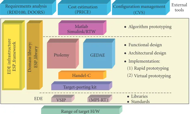
Requirements analysis
Range of target H/W
•Algorithm prototyping
Figure4: ESPADON design environment.
(a) increasing productivity and decreasing development time,
(b) providing additional architecture choices,
(c) using better quality constituent parts since they have already been tested and validated,
(d) capitalising on existing know-how.
1.3. The overall environment
An integrated software design environment, the ESPADON design environment (EDE), was developed to support the methodology and reuse and capitalisation policy described above. It is based on a collection of COTS software tools that were selected as the most suitable after a detailed re-view and evaluation of many commercial EDA (electronic design automation) tools. This environment is shown in Figure 4 below. Two of the tools, Ptolemy Classic [5] and GEDAE, Blue Horizon Development Software, Mount Lau-rel, NJ, USA, http://www.gedae.com/, form the core of the environment as they fully support and are integral to the concept of RP. Handel-C [6,7,8] was used for FPGA hard-ware synthesis to provide an analogous process route to pro-grammable logic as to microprocessors. The domain library (ESP Library) contains the reused elements for an SP appli-cation domain (radar, sonar, etc.). This library is based on the vector scalar image processing library (VSIPL) standard, http://www.vsipl.org/.
The radar and sonar benchmarks of the RP process were performed using the environment and Ptolemy Classic and GEDAE, respectively.
2. THE BENCHMARKS
The choice of signal processing applications for the bench-mark was arrived at by considering two factors. One was that it must be a common application for the two domains,
radar and sonar, so that the conventional development pro-cess and associated metrics are known, or can be confidently estimated. The second was that a common subset of the ap-plication exists for both domains, for cross comparison, and is of small but sufficient size (functionality and development effort) to enable the benchmark measurements to be made within the time and effort available and to be acceptable.
Beamforming, the processing of sensor signals into di-rectional beams, was selected as the application subset that would be benchmarked. It is a generic processing func-tion for both domains and satisfies the selecfunc-tion criteria. The functional processing chain for the radar and sonar beamformer benchmarking applications is described in the next two sections.
2.1. Radar
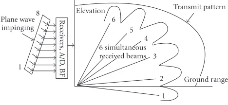
The application subset is from a ship-based X-band air surveillance radar with a vertical array of, for example, eight transmit and receive elements. Each element is a horizontal linear stripline array of dipoles. Elevation beams are formed by the digital beamformer that performs an 8-point FFT al-gorithm on the outputs of the eight receiver channels. In this way, a multibeam receive system is formed, Figure 5. The benchmark concerns only the receiver beamforming func-tion, the transmit beamforming function is implemented by an analogue system.
The beamformer is adaptive with respect to the ships course and speed, and the ships roll and pitch movement. This results in a phase correction that is applied to the complex data stream prior to the beamforming, together with windowing and calibration correction. The functional processing chain is shown inFigure 6.
8
Figure5: Multibeam receive system.
resident on the host machine and part of the stimuli genera-tor and/or display.
For a first RP implementation, the target platform was an embedded VME system from Mercury Computer Sys-tems (http://www.mc.com/). This comprised three Mer-cury motherboards, each connected via interlink modules through two ports to the high-speed RACEway interconnect between the boards. One motherboard was equipped with two daughter boards with two Motorola power PC altivec processors (http://e-www.motorola.com/) each, and the two other motherboards with one daughter card with two altivecs and one daughter card with 512 MB memory each. This re-sulted in a machine with eight processing nodes and bulk memory that was used for real-time data playback of the (stored) stimuli generator data and for logging of the inter-mediate/output results of the application.
In a second RP implementation, the time-critical part of the beamformer application, that is, the beamforming func-tion, was ported onto an FPGA board. The rest of the appli-cation remains mapped onto the Mercury boards. The FPGA board was an existing board from Thales Airborne Systems with two Xilinx Virtex XCV400 devices.
Within Ptolemy Classic, the radar benchmark applica-tion has first been modelled and simulated with synchronous data flow (SDF) [9] and Boolean data flow (BDF) [10] mod-elling formalisms. Then the code has been generated with the code generation C (CGC) computation domains [11]. A target porting kit (Figure 4) has been developed in Ptolemy Classic to generate, compile, load, and run the code of the power PCs and the FPGAs.
In addition, other specific enhancements had to be car-ried out in Ptolemy Classic to support the RP process and the benchmark [12].
(i) Additional library components; radar library—five components; VSIPL core light library—11 compo-nents; and support library (e.g., components for par-allel operation)—19 components. These components were developed for SDF, CGC, and HDLC (see be-low) computation domains. The components and the domains were identified in the early Ptolemy bench-mark developments as being required if the func-tional requirements of the benchmark were to be addressed.
(ii) Support for the VSIPL altivec power PC optimised
li-brary and static memory allocation of VSIP views dur-ing the initialisation phase of the target machine. (iii) Support for performance monitoring using Mercury
trace tools.
(iv) Extension of the BDF code generation domain to sup-port use within a single processor which was part of a multiprocessor architecture modelled using the mul-tiproc CGC domain. The rationale was to enable sup-port and integration of control functions which are in-tegral to most sensor platforms.
(v) Addition of a new code generation domain “HDLC” to generate code in the Handel-C language instead of C so as to map directly to programmable logic. Handel-C is a hardware design language very similar to Handel-C, but Handel-C has some specific functionality dedicated to the design of hardware components.
(vi) Support for heterogeneous architecture code genera-tion [13]. The characteristics of the codes generated for the power PCs or the FPGAs are different, that is, different languages (C or HDLC), different memory al-location, and different communication drivers. Never-theless, these two types of codes implement the same communication protocol to interface the two architec-tures.
Only manual partitioning was used for the mapping of the functional SDF model into the targeted architecture. Al-though automatic methods of partitioning exist within the Ptolemy tool, these rely on estimates of the execution time of each of the low level building blocks used to create the model at schedule time. Sufficiently accurate estimates were not available because:
(i) the building blocks used VSIP library functions where the size of data to handle, and hence its execution time, is only known at runtime,
(ii) obtaining accurate estimates is complicated due to the complex cache policy of the PPC and Mercury archi-tecture.
Beamformer functional diagram
Level stab shift, CVE phase, RF, receiver STC
Beamformer monitor & control BF status
Figure6: Radar functional processing chain.
2.2. Sonar
The application subset is from a generic ship/submarine-based active sonar system. It covers the core functionality of a conventional beamformer and an adaptive beamformer where the reverberation due to the propagation environment is estimated and cancelled. For a given sonar array head-ing and speed, the reverberant returns from any particular direction have an induced Doppler which depends only on the directions of transmission and reception, nonzero in-trinsic Doppler being ignored. This means that all beams re-ceive their reverberant noise in a given Doppler bin from the same direction. This includes the few beams, whose direc-tions align with the direction of arrival of the reverberant re-turns being considered, which of course will have their zero Doppler ridges at the Doppler bin being considered. In fact they are these few beams which are used in the adaptive al-gorithm as reference beams to sense the reverberation at the Doppler bin in question, and cancel it from all other beams.
The overall functional processing chain (top diagram) and the beamformer functions (bottom diagram) are shown inFigure 7. The latter were developed for the RP benchmark and interfaced to other functions, primarily for I/O, such as the scenario generator and/or display resident on the host machine.
The sonar benchmarking application was developed within the RP process using GEDAE with an initial and final target embedded VME systems, each connected to a sun workstation. The initial embedded system was from Sky computers (http://www.skycomputers.com/) and was used to develop the benchmark application functions. This platform consists of a force SPARC CPU50 host machine and two-quad power PC altivec processor (Merlin) pro-cessing boards connected together by the backplane Sky channel interface. The final system was a subset devel-oped on the EUROPRO project [14] and was used to com-plete all the sonar benchmark measurements. This platform was chosen because it is based on different processors to
the other ESPADON target platforms and would demon-strate the hardware independence of the RP process. It has a number of DBV66 boards, Blue Wave Systems DBV66 ADSP-2106x Carrier Board Technical Reference Manual, Blue Wave Systems (http://www.bluews.com/) each with six analog devices “SHARC” DSP processors, Analog Devices (http://www.analogdevices.com/technology/dsp/). In the ba-sic configuration,Figure 8, there are two DBV66 cards con-nected via the VME to the host board for code load. All further communication between SHARC processors are per-formed using point-to-point SHARC links which are capa-ble of MB/s data transfer rates. Multiple DBV66 boards are connected using the internal SHARC links to support larger SHARC networks.
A target porting was developed for this platform for GEDAE. It is built on underlying support software for the platform, such as the blue wave IDE6000-V4.0, Blue Wave Systems (http://www.bluews.com/), the operating system Virtuoso 4.1-R2.04 for Solaris (http://www.windriver.com/) (formally owned & distributed byhttp://www.eonic.com/), and the analog devices compiler-V3.3 for Solaris. The over-all EDE enabled the GEDAE data flow graphs to be devel-oped for the benchmarking functions across a number of platforms, including the host, by different users and simply imported and/or ported to the benchmarking platform.
The key functions developed for the benchmark were
(i) data generator—read data in from a file that has been generated from the stimulator. The simulator provides hydrophone data (128 hydrophones) of complex base-band reverberant time series data across an array of specified elements;
Scenario generator and benchmark operator’s interface
Stimuli gen hydrophone data store
Conventional beamformer
Adaptive beamformer
Data processing
Display processing
Beamforming coefficients Conventional beams out
Conventional beamformer &
base bander
FFT & Doppler
binner
Reference beam selection
Adaptive reverberation
canceller Baseband hydrophone
samples
Conventional beams & coeffs. into adaptive beamformer
Adapted beams out
The conventional beamformer The adaptive beamformer Figure7: Sonar functional processing chains.
VME
FPGA board
2×DBV66 2×6 SHARC DSPs
SPARC CPU50 SCS12 disk
TCP/IP
Host machine Sun/PC
Figure8: Sonar hardware configuration.
(iii) conventional beamforming—comprises components that are to be used within the adaptive beamforming functionality. The current function box has three out-puts:
(1) beam samples (for each beam),
(2) steering vectors (for each hydrophone/beam), (3) weighting vectors (for each hydrophone/beam). The last two output parameters are not essentially part of a conventional beamformer, but are formed, as they are required, parameters for the adaptive part of the benchmark functionality;
(iv) reference beam selection—algorithms to select the beams whose directions align with the direction of ar-rival of the reverberant returns being considered; (v) adaptive reverberation cancelling—adaptive
algo-rithms that use the reference beams to sense the rever-beration at the Doppler bin in question, and cancel it from all other beams.
For the benchmark, the conventional beamformer, being fully understood and previously developed many times, could be implemented in its entirety within the GEDAE en-vironment using the “embedded functions” available within the tool at both the host and optimised target level. The adap-tive beamformer however required significant algorithm in-vestigation and the development of specialist sonar library components, ten in total, to satisfy the needs of the specifi-cation. These components were all generated in high level C code and were not optimised for target execution.
Following the sonar benchmarking activity, an FPGA board was also connected to the VME to demonstrate het-erogeneous implementation capability. A design flow linking the GEDAE and Handel-C tools was demonstrated, as a tech-nology demonstrator only, and no benchmark metrics were collected for this activity.
3. THE METRICS
The objective of the benchmarks was to measure the perfor-mance of the ESPADON RP signal processing design envi-ronment with respect to the project goals: reduction in the product lifecycle cost and lifecycle time, and improvement of the product quality.
The measurements were through small design exercises, developing the benchmark applications described earlier, in order to capture basic metrics regarding the process and the product. The fundamental performance process metrics in-clude design cycle time, nonrecurring cost, ease of use, and supportability. Performance product includes cost to manu-facture, cost to maintain conformance to requirements, and dependability.
(i) Evaluate the RP process:
(1) comparison with current practice: develop cur-rent practice base-line costs and schedule; (2) performance metrics: employ metrics to measure
and substantiate improvements;
(3) improvement: identify weaknesses in the design process.
(ii) Evaluate the tool integration:
(1) integration: verify the degree of tool integration, including libraries and databases;
(2) ease of use: provide qualitative ease of use evalu-ation for the tools and processes;
(3) improvement: identify weaknesses or missing el-ements in the tool set.
(iii) Evaluate the signal processing system (products): (1) architecture: assess the suitability and scalability
of the HW and SW architectures;
(2) compliance: measure the compliance of hard-ware and softhard-ware to supplied requirements; (3) cost: provide current practice cost comparison.
Hence, the metrics that are needed to be measured are of dif-ferent types. They can be summarised as belonging to one of the metric sets below.
Principal and supporting metrics
Considered to be the most important metrics. They must provide us with hard numbers regarding the improvement obtained by using the ESPADON methodology and directed toward specific issues of performance of both the ESPADON process and products, that is, reduced design cycle time, re-duced cost, and improved quality.
Tool-oriented process metrics
Indicate more about the support which is given by the EDE and its constituent tools. While the principal and supporting metrics are important to the success of the ESPADON ap-proach, the user’s perception of ESPADON will be strongly influenced by the ease of use and uniformity of the EDE. De-veloping quantitative tool metrics to directly measure sub-jective attributes is a difficult if not an impossible task. How-ever, certain attributes of the EDE can be measured, such as the consistency of the user interface, tool integration facili-ties, and so forth, bear some correlation with qualitative at-tributes such as ease of use.
Application complexity metrics
These primarily focus on the elements, products, or applica-tions to be developed. The objective is to capture the inher-ent complexity of a given benchmark application, indepen-dent of the particular hardware and software implementa-tion. The metrics will also serve as a reference for determin-ing efficiency of the hardware and software realisations of a benchmark produced by the developer. In addition to com-plexity measures of the functions themselves such things as requirements of external interfaces, requirements for testa-bility, reliatesta-bility, and maintainatesta-bility, and requirements con-straints are also considered.
Product complexity metrics
Various types of products will be produced during the ES-PADON design process. These include software, hardware, and documentation. Even within a category, a variety of types of products may be produced. For example, in the soft-ware category products may include real-time application code, test code, simulation code, and so forth. For each sig-nificant product developed in the course of a benchmark, complexity metrics are required to characterise the efficiency of the product and the difficulty of implementation.
Product performance metrics
Measuring the performance of products produced using ES-PADON is different from measuring the performance of the ESPADON process itself. Misapplying a good process may produce poor products. These metrics aim to characterise the resulting performance of the individual products produced, for example, for a software product such things as compu-tational efficiency, postrelease defect density, portability, and adherence to standards and testability are considered.
The measured metrics and summary of the important benchmark results are presented inSection 4.
4. THE MEASUREMENTS
There are distinct differences in the benchmark measure-ments of the sonar and radar applications. These are at-tributable to the difference of approaches of the two bench-marks. The sonar benchmark relied on GEDAE, a mature COTS tool for RP prototyping whereas the radar bench-mark upgraded the open source Ptolemy Classic tool. In each case, the reference to conventional developments and processes refers to the existing methods and processes be-ing used within the company performbe-ing the benchmark-ing activity. In general, these consisted of disparate groups of engineers performing a particular function within a typical V or waterfall development lifecycle with communication of requirements/specifications via paper documents. The base-line estimates refer to the time taken to perform the develop-ments using these conventional approaches. They have been obtained using metrics available from previous develop-ments of similar products and estimates produced from ex-perienced engineers within the disparate groups mentioned above. In both cases, a final implementation using these con-ventional methods was not available to the developers and so a detailed comparison of performance between the base-line and the new developments was not possible. However, in both cases a level of performance was specified for the fi-nal implementation, and for the benchmarks to be successful, these had to be met.
4.1. Sonar
Table1
Activity (% of total) Effort
Functional design: specification (14%), design (28%), implementation (42%),
verification (13%), review (3%) 93 hours
Functional design 2: specification (14%), design (24%), implementation (24%),
verification (24%), review (14%) 21 hours
Architecture design/implementation—5 iterations specification (11%), design
(33%), implementation (11%), verification (11%), review (33%) 45 hours
(A) Total development time 159 hours
(B) Baseline estimate—including error correction 2537 hours
Performance improvement factor A/B 16
Sonar benchmark primitives
Figure9: Sonar benchmark primitive count.
performance, latency, and throughput, on the hardware ar-chitecture provided for the benchmark. The baseline esti-mate is from conventional developments for the same func-tions by Thales Underwater Systems which undertook the sonar benchmark activity. We attribute the significant pro-ductivity improvement to two factors. One is that the con-ventional beamformer is a fully understood and specified ca-pability implemented many times within the company on a variety of different target architectures. The second is that the RP process enabled the application to be implemented in its entirety within the GEDAE environment using the “embed-ded functions” available within the tool at both the host and optimised target level. No specific sonar library components had to be generated for this application resulting in a high level of reuse and productivity.
In the case of the adaptive beamformer, the improvement factor is less because a number of new embedded functions had to be developed, as shown byFigure 9. Ten library com-ponents were developed, with approximately 1000 lines of code in total, across all components. These components were all generated in high-level C code and were not optimised for target execution. As can be seen in the middle of the graph it was sometimes necessary to remove boxes during redesign. This redesign usually required the development of new user-generated primitives to provide the required capability.
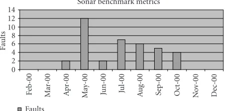
A significant reduction in faults was identified, includ-ing reduced time to locate and remedy such faults, whilst
Sonar benchmark metrics
Figure10: Sonar benchmark fault count.
implementing the adaptive beamformer once a level of un-derstanding of the tool had been achieved by the developers (Figure 10). This meant that execution of the capability on the target machine resulted in no functional errors and al-lowed the developer the time to concentrate on the efficient partitioning of the capability rather than its algorithmic per-formance.
Another important metric measurement was the number of iterations of the design as shown inTable 2. Though more than planned, the rapidity with which designs could be iter-ated within the RP process enabled high productivity factors to be maintained. In fact, there were many more very short iterations that were not reported simply because they were too short but nevertheless important in converging to an ac-ceptable solution. In the table below, an iteration is defined as being one pass through the process for the production of a product, for example, an algorithm, with particular func-tionality. Hence, additional iterations are required where the output of the particular process has not converged to an ac-ceptable solution and has to be further refined during further iterations. So in the case of the time varying gain product, five iterations of the process were required, which covered initial development through improved functionality to opti-mised performance, before an acceptable solution that met its requirements was reached.
Table2
Activity Phase Iteration
Planning Planning 1
Specification Specification 1
Data generator Functional design 1
Conventional beamformer Functional design 1
Adaptive reverb cancellor Functional design 15
Time varying gain Functional design 5
Reference beam selection Functional design 7
Control interface Functional design 1
Conventional beamformer Architecture design 2
Total iterations 34
Table3
Bare beamformer Design 1 Design 2 Design 3 Design 4
Nofchannel 8 8 8 8
Nofsweep 17 17 17 17
Nofproc 4 (+2) 5 (+2) 4 + 4 8
Input data DMA DMA Pre-load Pre-load
Output data (DMA) (DMA) (DMA) (Pb MCS)
Corner-turn 4−>4 NO 4−>4 8−>8
RACE++ peak load — — — 53%
Latency 1 burst 1 burst 2 burst 1 burst
Performance 25 ms 21 ms 9.5 ms 9 ms
Support var. burst L. Yes Yes Yes Yes
Design time 72 H 16 H 12 H 16 H
methods. This gives a productivity improvement of factor of 2.4. In terms of the reduction of coding errors, the com-parison for the adaptive beamformer shows a factor of eight (conservative) reduction compared to conventional meth-ods. This is attributable to the RP process providing algo-rithm developers/system analysts and software developers with the benefit of the use of a common development en-vironment.
4.2. Radar [15]
In this case, a significant part of the benchmark work was tightly coupled to enhancing the Ptolemy Classic support en-vironment for the target heterogeneous multiprocessor ar-chitecture and its integration within the overall EDE. Hence, the metrics covered more aspects of the RP process than the sonar benchmark. In particular
(i) more metrics were measured related to the application complexity, to the methodology and tool support, to the performance of the application and the libraries, to the validation process, and to the overall RP process; (ii) metrics were measured for a heterogeneous RP
archi-tecture mixing FPGA and power PC.
For the first implementations on the Mercury platform, the benchmark application required in total eight design
itera-tions to complete before converging to a real-time perfor-mance compliant solution, that is, meeting the overall la-tency figure required for the processing. Results for four of the design iterations are shown in Table 3. For these cases, the improvements of the real-time performance (from 25 to 9 millisecond) between the iterations resulted from an itera-tive process based on
(i) an analysis of the real-time performance of the previ-ous iteration implementation, in order to identify the time-consuming components and the communication bottlenecks;
(ii) an optimisation of the mapping of the radar applica-tion into the Mercury platform PPCs;
(iii) an upgrade of the code generators and the library com-ponents developed in Ptolemy Classic for the bench-mark;
(iv) the execution of the new application implementation with the upgraded mapping and generated code.
The following Figures11,12, and13summarise the mea-surements for the overall design of the first RP implementa-tion, the test and validation and the application complexity, respectively. The right vertical axis presents cumulative totals represented by the dots. The figures present the results for a nonadaptive beamformer (bare BEFO) and for the full adap-tive beamformer (full BEFO)
The overall time measured to implement (coding) and test/integrate the application was 354.5 hours. Thales Naval Nederland which undertook the radar benchmark have cal-culated a baseline figure of 481 hours for a conventional pro-cess. Hence, this gives an improvement factor of 1.4. The lower figure is attributable to the many more enhancements that had to be carried out with Ptolemy Classic thereby re-ducing the level of (re)-use of existing functions for the benchmark. However, future developments of similar appli-cations will not have to incur all of these library component developments and hence this improvement factor will in-crease. InFigure 13, we finally present the complexity of the major iterations in terms of generated lines of code (LOC) as well as number of functions used in the designs.
The final benchmark implementation was based on a Mercury and FPGA heterogeneous platform. This Bench-mark was not a real-time implementation since the commu-nication between the Mercury boards and the FPGA board employed a low-bandwidth VME bus instead of the high-speed RACE++ interconnect between the Mercury boards.
The beamformer application after simulation (SDF/BDF) was mapped on three different configura-tions: 1 PPC/1 FPGA, 4 PPCs/1 FPGA, and 4 PPCs/4 FPGAs. The Handel-C code was generated for these three different implementations. Only the two first solutions where finally synthesised and tested into the FPGA.
Performance results of the FPGA implementation were for the 1 PPC 1 FPGA configuration:
(i) 67% of SLICES (63536 gates, 3481 flip-flops) used, (ii) maximum frequency=21.8 MHz,
and for the 4 PPC 1 FPGA configuration:
(i) 99% of SLICES (97270 gates, 5052 flip-flops) used, (ii) maximum frequency=17.2 MHz.
Due to the I/O limitation of the FPGA board, the perfor-mance of the beamforming FFT was tested as being a fac-tor of three times slower on the FPGA than on the PPC (ap-prox. 1.1 microsecond per FFT8). Although real-time perfor-mances were not demonstrated, the benchmark enabled the measurement of the design complexity and design time du-ration and the estimation of the development time speed up improvements.
InFigure 14, the complexity of the designs is summarised in terms of generated LOC as well as number of functions used in the designs.
Although the development for supporting the heteroge-neous architecture was at first highlighted as a high-risk ele-ment, it actually took just over three engineer months. This included the development of the new Handel-C domain in
Benchmark design development
S-00 O-00 N-00 D-00
Definition Bare BEFO
Figure11: Radar design and development duration.
Benchmark design test and validation 70
S-00 O-00 N-00 D-00 J-01
Test bare BEFO Test full BEFO
Review Total
Figure12: Radar test and validation duration.
Design complexity
Design complexity
Figure 14: Design complexity of the RADAR benchmark imple-mented on the heterogeneous platform.
Ptolemy Classic, a new target supporting the mix of Mercury compute nodes and FPGAs, the needed Handel-C library de-velopments, and HW/SW integration activities.
The heterogeneous platform benchmark was more lim-ited than the mercury-based benchmark nevertheless a sig-nificant improvement of the development time by using an RP environment can be estimated. In the conventional de-velopment methodology, the design of an FPGA with this kind of complexity would take approximately 500 hours, in-cluding documentation. If we only focus on the develop-ment process, this reduces to approximately 300 hours. Com-pared to the development time using the EDE (40 hours), this means an improvement of 7.5 was achieved.
5. CONCLUSIONS
An adaptive beamformer application for a radar and sonar was successfully designed, implemented, tested, and bench-marked using the EDE and the ESPADON RP process. An improvement factor of 1.4 and 2.4 in productivity was demonstrated for the radar and sonar beamformer applica-tion, respectively. Hence, we can be confident that a halv-ing of embedded signal processhalv-ing system development life-cycle can be achieved using the RP methodology and sup-port environment. A much higher factor of 16 was achieved with a conventional sonar beamformer. This implies that sig-nificantly higher factors are possible through the use of a common RP process and environment and the development of application domain libraries to maximise future (re)-use of signal processing functions.
An important finding and factor towards these produc-tivity gains is that the functional, architectural and imple-mentation design are done simultaneously instead of sequen-tially simply because it is so easy and fast to do these with the RP environment. This demands for a different process that allows for rapid and higher frequency types of itera-tions. Also many feedback loops are performed towards the
redesign of the environment. This allows for very rapid itera-tions to arrive at the correct design and reduce error propaga-tion. The latter also benefited from a common RP environ-ment and the exchange of information as graphical designs that can be quickly integrated into the overall functional de-sign.
The approach has been found to be scalable to larger de-signs than the benchmark applications discussed in this pa-per, although this is to a certain extent a function of the tool rather than the rapid prototyping methodology. Indeed, both the tools discussed have a mean of automatically scaling ele-ments of the design under parameter control. This is partic-ularly useful in such sensor-based systems where a trade-off analysis with respect to say the number of beams and per-formance can be conducted without modifying the overall structure of the model.
Although the work has focused on rapid prototyping onto COTS processor-based components, the ESPADON methodology is also applicable to the development of algo-rithms for proprietary hardware platforms such as system-on-chip (SOC). This would also involve the use of techniques such as virtual prototyping, that is, the development of a model of the system to execute on a virtual model of the final hardware. These techniques and their supporting tools were found to be far less mature than those available for rapid pro-totyping. However, rapid prototyping is an important step towards defining the data required for virtual prototyping techniques in order to produce a sufficiently accurate perfor-mance model of the algorithms and to scope the proprietary developments.
Signal processing functions are only one part of an em-bedded sensor system. Further work needs to be done to ex-tend the RP process to include other functions such as system control, front-end interfacing and processing, back-end data processing and the HCI for commensurate productivity im-provements at the system level. These topics require further research and development.
NOTE
Unless BAE SYSTEMS (Operations) Limited, THALES or MBDA has accepted a contractual obligation in respect of the permitted use of the information and data contained herein, such information and data is provided without re-sponsibility. BAE SYSTEMS (Operations) Limited, THALES and MBDA disclaims all liability arising from its use.
ACKNOWLEDGMENTS
presented at the internal BAE SYSTEMS Signal and Data Pro-cessing Conference, 5–7 March, 2002, Dunchurch Park Con-ference Centre, UK, ConCon-ference Proceedings pages 1–21.
REFERENCES
[1] ESPADON Programme Deliverable, “ESPADON: Final Re-port,” Tech. Rep. Dex 45990, Thales Airborne Systems, Elan-court, France, September 2001, Project EUCLID-CEPA 2-EUROFINDER contract no. 97 34 391 00 470 75 65. [2] J. Pridmore, G. Buchanan, G. Caracciolo, and J. Wedgwood,
“Model-year architectures for rapid prototyping,”The Journal of VLSI Signal Processing Systems for Signal, Image and Video
Technology, vol. 15, no. 1-2, pp. 83–96, 1997, Special Issue on
Rapid Prototyping of Application Specific Signal Processors (RASSP).
[3] J. P. Calvez, Embedded Real-Time Systems. A Specification
and Design Methodology, John Wiley, Chichester, Sussex, UK,
1993.
[4] B. W. Boehm, “A spiral model of software development and enhancement,”IEEE Computer, vol. 21, no. 5, pp. 61–72, 1988. [5] Ptolemy, Department of Electrical Engineering and Com-puter Sciences of the University of California, Berkeley, Calif, USA,http://ptolemy.eecs.berkeley.edu/.
[6] Handel-C (DK1) Celoxica, Abingdon, Oxfordshire, UK,
http://www.celoxica.com/.
[7] M. Fleury, R. P. Self, and A. C. Downton, “Hardware compi-lation for software engineers: an ATM example,”IEE
Proceed-ings Software, vol. 148, no. 1, pp. 31–42, 2001.
[8] M. Vasilko, L. Mach´acek, M. Matej, P. Stepien, and S. Hol-loway, “A rapid prototyping methodology and platform for seamless communication systems,” in12th International
Workshop on Rapid System Prototyping (RSP ’01), Monterey,
Calif, USA, 2001.
[9] E. A. Lee and D. G. Messerschmitt, “Static scheduling of synchronous dataflow programs for digital signal processing,”
IEEE Trans. on Computers, vol. 12, no. 8, pp. 971–989, 1987.
[10] J. T. Buck, “Scheduling dynamic dataflow graphs with bounded memory using the token flow model,” Tech. Rep. UCB/ERL 93/69, Ph.D. Dissertation, Department of Electrical Engineering and Computer Sciences, University of California, Berkeley, Calif, USA, September 1993.
[11] S. S. Bhattacharya, P. K. Murthy, and E. A. Lee,Software
Syn-thesis from Dataflow Graphs, Kluwer Academic Publishers,
Norwell, Mass, USA, 1996.
[12] D. Aulagnier, P. Meyer, H. Schurer, and X. Warzee, “Rapid prototyping of RADAR signal processing systems using Ptolemy Classic,” inProc. Ptolemy Miniconference, University of California, Berkeley, Calif, USA, March 2001.
[13] J. L. Pino, M. C. Williamson, and E. A. Lee, “Interface syn-thesis in heterogeneous system level DSP design tools,” in
Proc. IEEE Int. Conf. Acoustics, Speech, Signal Processing, pp.
1268–1271, Atlanta, Ga, USA, May 1996.
[14] EUROPRO Consortium, “EUROPRO Final Report,” Tech. Rep. Project P21040-HPCN/EUROPRO, V1.1, Thomson Marconi Sonar, Sophia Antipolis, France, May 1999. [15] H. Schurer and J. J. Hunink, “Rapid prototyping of radar
signal processing algorithms,” inIEEE Workshop on
Process-ing, Integrated Systems and Circuits (ProRISC ’99), Mierlo, The
Netherlands, November 1999.
Bob K. Madahar graduated with special honours in physics in 1976, followed by a Doctorate in space physics from the Univer-sity of Sheffield before being appointed for a three-year postdoctoral research fellowship at Lancaster University in the Environmen-tal Sciences Department. He joined indus-try in 1982, as a Scientist in a leading Scien-tific and Computer Consultancy Company in Cambridge before moving in 1991 to the
Long Range Research Laboratory, Machine Vision Group, of the GEC-Marconi Hirst Research Centre. He has rapidly progressed from Team Leader, Group Leader to his current role of Chief Sci-entist of the Systems Department of the company, now BAE SYS-TEMS Advanced Technology Centre. Dr. Madahar has worked over the last two decades for industry and the government in many areas concerned with real-time processing of signals and high-performance computing. These areas have included active control of sound and vibration, fluid dynamics, oceanography, data fusion, parallel processing, and computer security, particularly trusted net-works. For the last ten years, he has been working on high perfor-mance distributed and embedded signal processing systems, par-ticularly the systems and architectures, design methods, and tools and algorithms to reduce system through life costs.
Ian D. Alstongraduated with a degree in mathematics from the University of Manch-ester in 1981. In 1984, he joined the Com-munications and Computing Laboratory at the Marconi Research Centre where he worked on several communications system design projects with particular emphasis on digital signal processing and protocols. Fol-lowing the merger of British Aerospace and Marconi Electronic Systems, he is currently
the Team Leader of the Future Architectures and Prototyping Tech-nologies team within the Systems Department of the BAE SYS-TEMS Advanced Technology Centre (Great Baddow). Most re-cently, he has been involved in the use of rapid prototyping tech-niques applied to embedded system design and was BAE SYSTEMS Project Manager of the Environment for Signal Processing Appli-cation Development and Prototyping (ESPADON) European Col-laborative project. This work is now being extended to fully hetero-geneous embedded architectures. He is currently the Project Man-ager and Technical Lead on the UK MoD CRP project on “Core-based DSP for FPGA,” reference CRP/01/S&E/SPI/IPI. This is part of the BEACON programme and involves Qinetiq, Malvern, and BAE SYSTEMS ATC as the industrial partner.
Denis Aulagnierreceived an Engineer de-gree from l’ ´Ecole Nationale Sup´erieure des Arts et M´etiers (1985) and an M.S. in electrical engineering from North Car-olina State University (1988). He worked at Thales Airborne Systems since 1988 where he was in charge or participated in the de-velopment of multiprocessor computers for radar digital signal processing. Since 1996, he participated also in different research
Hans Schurer was born in Nijeberkoop, The Netherlands, in 1967. In 1990, he re-ceived the B.S. degree in electrical engineer-ing from the Leeuwarden Polytechnic Insti-tute, The Netherlands. In 1993, he received his M.S. degree (cum laude) in electrical engineering from the University of Twente, Enschede. In November 1997, he obtained his Ph.D. from this same university. The subject concerned linearisation of
electro-acoustic transducers using nonlinear digital signal processing. Dur-ing this research, a prototype of a digital loud speaker system with nonlinear distortion compensation was designed and built for Philips Research Labs, Eindhoven. At the moment, he is employed at Thales Naval Nederland B.V. (formerly Hollandse Signaalappa-raten B.V.) in Hengelo, as a Digital Signal Processing Technical Au-thority. His main research interest is in antenna-based signal pro-cessing techniques for radar systems.
Mark Thomasis a Senior Systems/Software Design Consultant with over 18 years expe-rience of the UK sonar industry. In depth knowledge of sonar processing with ex-tensive experience in the design, develop-ment, integration, testing, and acceptance of large, and small, real-time sonar appli-cations on programmes such as 2046, 2050, and 2076. He is contributing to current TUS open systems studies. Consultant on the
ES-PADON (Environment for Signal Processing Application Devel-opment and Rapid Prototyping) programme, a trination Euro-pean EUCLID/EUROFINDER defence programme that success-fully completed in September 2001, and researched rapid (DSP-based) and virtual (FPGA) programming.
Brigitte Saget is presently with MBDA-France, Airborne Electronics Engineering Directorate. She has 25 years of experience in research and development of embedded electronics and software for aerospace and defence applications. Following her grad-uation from Ecole Sup´erieure d’Electricit´e in 1978, she joined MATRA Defense which became Matra BAe Dynamics and recently MBDA. From 1978 to 1984, she was