http://dx.doi.org/10.4236/wjet.2015.33C035
Fault Diagnosis Technology Based on Model
Driven
Xie Zhang
1, Zufeng Xu
1, Jun Wu
21Research and Development Center, NARI Technology Development Co. Ltd., Nanjing, China
2Transmission Maintenance Center, Jiangsu Electric Power Maintenance Branch Company, Nanjing, China
Email: [email protected]
Received 9 September2015; accepted 16 October 2015; published 23 October 2015
Abstract
Fault diagnosis is an important application of the power grids monitoring system. Under the situa-tion of continuous development of smart grid, it brings new challenges to the fault diagnosis tech-nology. A fault diagnosis expert system based on model driven approach is proposed in this paper. And the corresponding fault modeling technology based on Fault Logic Description Language (FLDL) is described step by step. Practices show that this system could meet the requirements of processing fault alarm information rapidly and reliably by operator.
Keywords
Fault Diagnosis, Model Driven, Fault Logic Description Language
1. Introduction
Fault diagnosis technology is one of the most important advanced applications in the smart substation [1] [2]. When the fault of power grid happens, it can analyze the related information, find the fault reason and send the fault report to the dispatching center. So it’s helpful for the operator to handle the situation. And it is also of great importance for the stable operation of power grid.
So far, various technologies of fault diagnosis have been proposed, such as the method based on the expert system, based on neural network and based on information theory [3]-[7]. The method based on the expert sys-tem is the most primary one among them. But it is inflexible to the various fault type which prevents it from be-ing utilized deeply.
In this paper, we studied a new fault diagnosis technology based on model driven. And the corresponding fault modeling technology based on Fault Logic Description Language (FLDL) is also explained step by step. Moreover, an application example in 500 kV Changshu Substation is introduced here.
2. System Architecture
The fault diagnosis system based on model driven can be mainly divided into three parts: alarm information process, alarm model resolution and fault reasoning machine. The architecture is shown in Figure 1.
Figure 1. System architecture.
information from the measuring-control and protection devices in real time and divide them into different levels and categories based on rules predefined in the database.
The alarm model resolution part is used to analyze the IEC61850 model information contained in the alarm [8]. After the resolution, the related information about the secondary device and the corresponding primary de-vice can be obtained. Also the matched fault model can be prepared for the further reasoning process.
The fault reasoning machine is the key part of fault diagnosis. It receives the alarm information from the alarm resolution part and compares it with all the constraint conditions stated in the fault model. When all the fault characteristics and the constraint conditions are satisfied, the corresponding result will be concluded and the reasoning report will be sent to the dispatching center.
3. Substation Fault Modeling Technology Based on FLDL
The fault model is the basis of substation fault diagnosis expert system. Based on the unified device model, the fault logic model can be abstracted from various fault logic. And Fault Logic Description Language is adopted to describe the model.
3.1. Substation Fault Logic Model
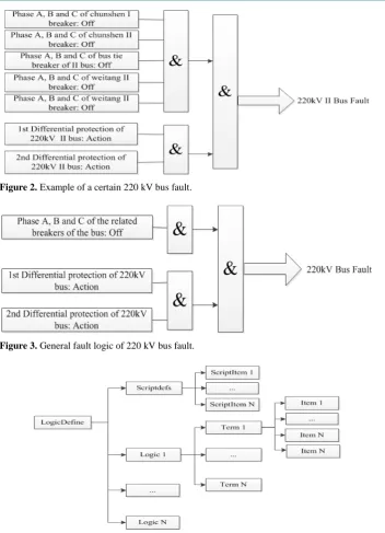
The substation fault is basically divided into two categories: secondary equipment fault and power grid fault. The fault logic of secondary equipment is mainly based on the alarm information and the measurement informa-tion, which represents a type of fault individually. The power grid fault relates to the voltage level, connection mode and the fault scale. According to the summarization of typical fault characteristics, a group of production rules can be concluded. Take a certain 220kV bus fault as an example, the fault logic is shown in Figure 2. In this figure, the breakers of chunshen I, chunshen II, weitang I, weitang II and the bus tie breaker are all the re-lated breakers of II bus. Based on its typical characteristics, we can obtain the general fault logic of 220kV bus fault as shown in Figure 3.
After the fault logic model has been concluded, a standardized format should be built to meet the require-ments of reading and maintenance. The former expert system is limited to use because of its fixed structure. In this paper, Fault Logic Description Language (FLDL) which can be recognized by the computer is proposed to describe the typical fault logic model.
3.2. Fault Logic Description Language
Figure 2. Example of a certain 220 kV bus fault.
Figure 3. General fault logic of 220 kV bus fault.
Figure 4. Fault model structure using FLDL.
The root element LogicDefine is the parent object of the other elements.
Taking into account of the arithmetic logical operation involved in the fault reasoning, the method of script calculate is adopted. The script formula is stored in the script file in advance. Scriptdefs element is the sub-element of LogicDefine. It defines the script files which will be quoted in FLDL. And ScriptItem is the sub-element of Scriptdefs which describes the path of the quoted script files.
Logic is also the sub-element of LogicDefine which defines a specific fault model as shown in Figure 3. Logic element describes the fault attributes such as voltage level, phase, scale and timeout.
with the data [3]. This method can help to process the fault alarm information rapidly. But its inflexible to the variable demand of fault logic holds back the progress of fault diagnosis technology. However, the fault diagno-sis by model driven can solve the problem effectively.
The key of model driven method is to load the standard model dynamically instead of binding it to the code. As we can see from Figure 5, the reasoning machine receives the alarm information from the resolution mod-ule and compares it with the launch condition of fault reasoning instance. When they match, the following rea-soning step will be carried out. If all the fault characteristics and the constraint conditions are satisfied, the fault reasoning completes and the corresponding result will be concluded. Finally, the reasoning result will be sent to the dispatching center.
The model driven method separates the fault logic and the program, which can simplify the process of rea-soning machine and improve the flexibility in application. Meanwhile, the whole process of rearea-soning machine is divided into three parts: the main flow of reasoning machine, the launch flow of logic instance and the process flow of logic instance. This method simplifies the complicated fault diagnosis process and also improves the ef-ficiency of reasoning machine.
5. Application
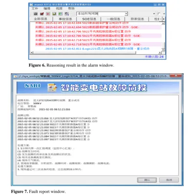
The fault diagnosis system based on model driven is already in use in 500kV Changshu Substation in Suzhou. Take the transient fault of transmission line as an example. The Sequence of Event (SOE) alarm information received by the alarm window is shown in Table 1. And the reasoning result is also shown in the alarm window as illustrated in Figure 6. Figure 7 shows the corresponding fault report window. Meanwhile, the reasoning re-sult and the fault report will be sent to the dispatching center via service bus for further analysis.
From the practical operation, the fault reasoning process can be completed in the fault period (time from the beginning to the end of the fault, usually 7 - 8 s) and send the fault report to the dispatching center. Compared with the traditional analysis method, the fault diagnosis by model driven is quicker, more accurate and more re- liable. It can not only deal with the typical fault, but also meet the requirements of complicated fault type. Moreover, the fault time, fault device, fault phase and the corresponding bay contained in the report is helpful for the operator to judge quickly and avoid the continuous expansion of influence.
Figure 6. Reasoning result in the alarm window.
Figure 7. Fault report window.
Table 1. SOE alarm information received by alarm window.
Time (ms) Alarm Information
0 Line protection of kuntai 2 (Phase A): Action 11 Line protection of kuntai 2 (Phase B): Action 22 Breaker of 5022 measuring-control device (Phase A): Off 34 Breaker of 5023 measuring-control device (Phase A): Off
46 Reclose of 5022 protection device: Action
57 Reclose of 5023 protection device: Action
68 Breaker of 5022 measuring-control device (Phase A): On 81 Breaker of 5023 measuring-control device (Phase A): On
6. Conclusion
[image:5.595.86.542.504.623.2][4] Cardoso, G., Rolim, J.G. and Zurn, H.H. (2004) Application of Neural-Network Modules to Electric Power System Fault Section Estimation. IEEE Trans on Power Delivery, 19, 1034-1041.
http://dx.doi.org/10.1109/TPWRD.2004.829911
[5] Mahanty, R.N. and Gupta, P.B.D. (2004) Application of RBF Neural Network to Fault Classification and Location in Transmission Lines. IET Proceedings of Generation, Transmission & Distribution, 151, 201-212.
http://dx.doi.org/10.1049/ip-gtd:20040098
[6] Srinivasan, D., Cheub, R.L., Poh, Y.P. and Ng, A.K.C. (2000) Automated Fault Detection in Power Distribution Net-works Using a Hybrid Fuzzy-Genetic Algorithm Approach. Engineering Applications of Articial Intelligence, 13, 407- 418. http://www.sciencedirect.com/science/article/pii/S0952197600000129
[7] Bedekar, P.P., Bhide, S.R. and Kale, V.S. (2011) Fault Section Estimation in Power System Using Hebb’s Rule and Continuous Genetic Algorithm. International Journal of Electrical Power and Energy System, 33, 457-465.
http://dx.doi.org/10.1016/j.ijepes.2010.10.008