905
MECHANICAL VEHICLE POWER GENERATING SYSTEM
MIN LIU
Chongqing University of science and technology, Chongqing 400050, China
ABSTRACT
Currently, the mechanical vehicle generating system is a relatively developed vehicle generating system that is widely used in a variety of places where mobile power supply is in shortage. This paper applies CATIA to process three-dimensional parametric modeling design for the power take-off and transmission of the system, using PROTEL DXP to design and analyze the electronic control part of the system. Firstly, this paper will determine the power taking project that takes power from the fifth gear output shaft gear of the transmission. Secondly, this paper will design and check the parameter of gear with gear transmission method after determining the transmission ratio. And finally the supporting project of gear will be arranged so as to design and check the gear shaft, as well as choosing appropriate bearing and spine.
Keywords: Power Take-off, Transmission Assemblies, Vehicle
1. INTRODUCTION
The rapid development of domestic economy has supplied us with more and more device groups in wild field operation, while the construction site is always located on a remote region which is far away from downtown, making these devices be unable to work without utility power, therefore, the power supply system has been considered as a project worth more consideration. Without utility power, vehicle special device is always assembled on the main vehicle using a diesel-driven generator set; alternately, dedicated power van can be used for power supply [1-3]. However, automotive engine has been regarded as the power source, which drives the vehicle generator to work [4]. Despite satisfying the normal requirement of driving condition, the multi-purpose automobile can also make power-supply for vehicle dedicated device by driving vehicle generator when parking [5, 6].
As for domestic vehicle generating, Doctor Guo Chusheng and Professor Wang Yu in Beijing Institute of Technology used EASYS to make simulation analysis for overall design and constant-speed control of vehicle generating system, moreover, they analyzed the feasibility of vehicle generating system, designed an overall control strategy for the system and studied on the optimized control technology of ob-board generating system on a circumstance of variable load and variable input speed [7]. In military developed countries such as the USA and Russian, vehicle generating system has stridden over the research stage to a stage of application, while domestic constant speed
driven vehicle generating research is still in a stage of developing, how to choose control strategy to ensure the quality of generator output power under a circumstance of rapid and significant change of engine speed while driving has been an unsolved problem [8, 9].
The research content of this design is mechanical vehicle generating system, which is mainly composed by automotive diesel engine; generator and the connecting transmission system (Power take-off, transmission shaft and electronic control).
2. PROJECT DESIGN
2.1 Determination of Transmission Scheme
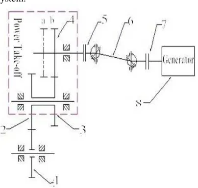
Figure.1 is the transmission scheme for the system:
[image:1.612.317.519.519.711.2]906 In this figure, Gear 1 is the output shaft gear of Transmission 5.Gear 2 is the take-off gear of Power take-off. Gear 2 and Gear 3 are designed as duplicate gears. When Gear 4 is at a position, the Power take-off won’t output torque. When Gear 4 is at b position, Gear 3 and Gear 4 will engage to transmit torque to output shaft for output. The position of Gear 4 is stirred by operation mechanism. Power take-off takes out torque and transmits power to a generator through coupling and cardan joint. This is the transmission scheme of entire generating system [10].
2.2 Generator Selection And Calculation Of Transmission Rate
2.1.1 Classification profile of generator
Generator can be simply classified as follows: DC generator, AC generator, synchro generator, asynchronous generator (rarely apply), while AC generator can be categorized into single phase generator and three-phase generator [11, 12]. This design approaches three phase synchro AC generator. The speed of rotor of synchro generator has absolute direct ratio with generator frequency, but for its disadvantage of unstable output voltage, power voltage stabilizer is often used to stabilize the voltage in application.
2.1.2 Generator selection
This design selected STC AC synchro generator of Beijing Subsidiary of Yingtai Group. ST/STC series synchro generator manufactured by this company has a history of nearly 30 years, with an annually production approximately to 10 thousand sets with excellent performance, and product authentication is: ISO9001-2000 [13, 14].
Principle parameter of STC-10 three phase generator. The casing is made by copper plate rolling, with a performance of small volume, fast heat dissipation and high strength. [15]
This generator applies star connection with neutral point of three-phase, line voltage: 400 V, phase voltage: 230 V, frequency: 50 Hz, power factor: 0.8 delay. The generator can be turned both positive and negative sides and is able to work under a rated and continuous condition [16].
2.1.3 Initial determination of transmission ratio Calculation of the transmission ratio of Power take-off. Transmission ratio calculation of Power take-off can be reached according to the determined operating speed of engine and operating device:
w x takeoff n itrans n i × =
In this formulation:
i
trans refers to the transmission ratio of transmission when take-offing,takeoff
i
is the transmission ratio of Power take-off,x
n
refers to take-off points of engine,n
w is the Transmission speed of Power take-off.Given: transmission ratio of fifth gear of NJ2045 transmission is
itrans
=1, take-off point of engineis
n
x =1200r/min, operating speed of engine isw
n
=1500r/min.Substitute in the formula:
8 . 0 min / r 1500 1 min / r 1200 = × = × = w trans x takeoff n i n i
Therefore, total transmission ratio of Power
take-off is chosen to be 0.8. Assume
i
1 to be the Level 1 transmission ratio of Power take-off (that is take-offtransmission ratio),
i
2 to be the Level 2transmission ratio. Initially designated as
i
1=0.8,2
i
=1.2.1.4 Motion and power parameter of transmission gear
Assume transmission efficiency of transmission
assembly is
η
T, transmission efficiency of bearingis
η
b
, transmission efficiency of cylindrical gearis
η
g.And calculates torque of each shaft according to{ }
r/min kw m N. } { } { 9549 n PMe ⋅ = × (1)
Generator shaft: Pe=10kw
N.m 66 . 63 9549 min / r 1500 = = = e e n Pe T ne
Output shaft of Power take-off: min / r 1500 = = g o n n kw 5175 . 10 9508 . 0 / 10 / 9508 . 0 98 . 0 98 . 0 99 . 0 = = = = × × = t t o t P P η η N.m 9544 . 66 1500 5175 . 10 9549
9549 = × ÷ =
= o o o n P T
Take-off shaft of Power take-off:
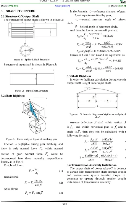
907 3. SHAFT STRUCTURE
3.1 Structure Of Output Shaft
The structure of output shaft is shown in Figure.2:
Figure 1: Splined Shaft Structure
[image:3.612.87.513.62.754.2]Structure of input shaft is shown in Figure.3:
Figure 2: Input Shaft Structure
3.2 Shaft Rigidness
Figure 3: Force analysis figure of meshing gear
Friction is negligible during gear meshing, and
there is only normal force
F
n within normalsection of gear. Normal force
F
n could be decomposed into three mutually perpendicular forces, as in Fig. 4.Peripheral force: 1 1 2 d T
Fτ = (1)
Radial force:
β
α
τ cos tan n r FF = (2)
Axial force:
β
τ
tan
F
F
a=
(3)In the formula: d —reference diameter of gear, 1
T1—torque transmitted by gear,
αn —normal pressure angle of reference
circle,
β—helical angle of reference circle. And then the forces on take-off gear are:
N 1 . 625 7939 . 23 tan 7 . 1417 tan N 9 . 563 7939 . 23 cos 20 tan 7 . 1417 cos tan N 7 . 1417 36 . 98 10 722 . 69 2 2 2 2 2 2 3 2 i 2 = ° × = = = ° ° × = = = × × = = β β α τ τ τ F F F F d T F a n r
Forces on Gear 3 and Gear 4 are equivalent as:
1549.4N 90 10 69.722 2 d 2T F 3 3 i
τ3 =
× × = = N 9 . 563 0 cos 20 tan 4 . 1549 cos tan 3 3 = ° × = = β α τ n r F F
3.3 Shaft Rigidness
In order to facilitate calculation during checking, output shaft is right under input shaft.
Figure 4: Schematic diagram of rigidness analysis of shaft
Assume deflection of shaft within vertical plan
is
f
c, and within horizontal plan isf
sand turnangle is
δ
, then they can be calculated with the following formula: 4 2 2 2 2 3 64 3 πELdb a F EIL b a F
f r r
c= = (4)
4 2 2 2 2 3 64 3 πELd
b a F EIL b a F
f t t
s = = (5)
(
)
(
)
4 3 64
3 πELd
a b ab F EIL a b ab F
δ= r − = r − (6)
3.4 Transmission Assembly Installation
[image:3.612.335.498.355.433.2]908
Figure 5: Assembly Drawing Of Transmission
There is a 10° intersection angel between transmission shaft and horizontal direction, this angel can be adjusted according to the assembly position of engine in actual installation.
Power transmission direction is core of transmission assembly, the selection of cardan shaft transmission shaft and reasonable lay out is an essential factor that influences the life time of system. Three-dimensional digital modeling design that based on CATIA is faster and more efficient than traditional drawing method, facilitating the speed of development and manufacturing of product significantly.
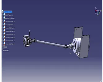
3.5 Overall Graphic Model of Mechanical Vehicle Generating System
The graphic model of the entire system is as Fig. 7:
Figure 6: Overall Graphic Model Of Vehicle Generating System
4. CONCLUSIONS
Mechanical vehicle generating system can be divided into three parts: power taking device, transmission system and electronic control system.
This paper is based on the following parts: transmission gear of IVECO NJ2045 has been applied to take power from the fifth output gear,
and CATIA has been used to process three-dimensional parametric design for gear, shaft, and casing of Power take-off. This power taking project has a rather simple structure compared with the taking power from clutch or power divider; moreover, it is easier for the arrangement of transmission assembly. Two gears of input shaft can be combined into a duplicate gear, which will simplify the entire Power take-off and facilitate processing. However, the problem of how to realize power supply while driving is still unsolved in this design, this problem calls for further research.
REFERENCES:
[1] Y.G. Hu, “Analysis on the Needs of Military Portable Power Station”, Portable Power
Supply and Vehicle, Vol. 2, No.2, 2001,
pp.23-25.
[2] C. Design, “CATIA V5 from Entry to Master “, Computer Engineering and Designing, Vol. 29, No.1, 2008, pp. 21-31.
[3] S.H. Li, Z.G. Pan, X.B. Meng, “CATIA V5Solid Modeling and Engineering Drawing Design”, Communication Journal, Vol. 65, No.1, 2009, pp.326-331.
[4] B.Z. Liu, et al, “MATLAB 7.0From Entry to Master”, Computer Engineering, Vol. 11, No.2, 2008, pp.90-92.
[5] X.J. Li, “Protel DXP Practical Tutorial of Wiring Design and Plate Making”, Computer
Usage and Software, Vol. 121, No.12, 2009,
pp.331-338.
[6] S.X. Nan, “Analysis on Quality Problem Summary of Military Portable Power Station”,
Computer Engineering, Vol. 1, No. 5, 2002,
pp. 8-10.
[7] S.M. Pieter, “Sluis Lou van der, Electrical power system essentials”, Computer Engineering, Vol. 12, No.9, 2009, pp.886-890.
[8] J.J. Zhang, “Modeling and Simulation Research of Hydrostatic Transmission System on Generating System in Walking Machines”
Computer Usage and Software, Vol. 26, No.1,
2009, pp.67-69.
[image:4.612.116.282.471.603.2]909
The Computer Science, Vol. 21, No.2, 2009,
pp.110-125.
[10]Y.H. Chen, J.C. Li, X.Y. Li, et al, “Implementation of Single-phase Inverter Based on DSP”. The Computer Science, Vol. 81, No.1, 2010, pp.23-29.
[11]Y.F. Chen, “Single-Phase Hybrid Excitation Shaft Generator and Its Voltage Stability Characterize for Vehicle Loads”, Harbin
Computer Engineering and Designing, Vol. 12,
No.21, 2011, pp.433-441.
[12]F. Hu, Y.X. Li, “Development of Special Car Load Generating Electricity System Called Halt Car Taking Dint Generating Electricity”,
Communication Journal, Vol. 2, No.21, 2011,
pp.231-234.
[13]G. Li, “Design of Automatic Control of Burner in Vehicle Generating System”,
Communication Journal, Vol. 43, No.1, 2011,
pp.554-560.
[14]M.M. Li, C.F. Zhao, et al, “Design and Installation of an On-board Electric Generator System”, Computer Engineering and Designing, Vol. 12, No.4, 2011, pp.763-766.