CORRELATIVE ANALYSIS ON ENHANCED DESCENDENTS
OF LEACH PROTOCOL FOR WIRELESS SENSOR
NETWORKS
1R.M.DILIP CHARAAN, 2Dr.R.RAMESH
1Research Scholar, College of Engineering Guindy, Anna University,Chennai,India
2Associate Professor, Electrical and Electronics Engineering, Anna University,Chennai,India
Email: 1 [email protected] , [email protected]
ABSTRACT
Wireless sensor networks (WSN) consist of a collection of sensor nodes sensing and storing data. In the WSN, the sensor nodes have limited transmission power and processing capability due to the limited energy resources. Infrastructure creation and data dissemination process in the Wireless sensor networks have been conventionally treated as the independent problems. Cluster Head selection plays a vital role in design of routing protocols. In this routing protocol individual and random mobile nodes are connected with the solar panel. Though we have many number of mobile hosts in the wireless network, connected with solar equipped system are capable to act as Cluster Head. To reduce the computational and communication costs we invoke an on-demand Cluster Head selection. However, the challenge is about to choose the Cluster Head among solar connected nodes and also various hierarchical routing protocol that are derived from Low Energy Adaptive Clustering Hierarchy (LEACH) have been analysed and surveyed. This paper also highlights the advantages and drawbacks of various Hierarchical routing protocols. The performance is evaluated using Network Simulator-2 and the results are shown.
KEYWORDS
:
Wsn,Routing,Hierarchical,Cluster Formation,Leach,Alive Nodes,Packet Delivery Ratio1. INTRODUCTION
Wireless sensor networks is a dynamic research area, set of enormous number of sensor nodes that are capable of sensing, establishing wireless sensor communication among the nodes doing computational and processing operations. It has a wide variety of applications with
immensely varying requirements and
characteristics. Wireless Sensor Networks offer unique benefits and versatility in terms of low-power and low-cost rapid deployment for applications which does not require human supervision. Nodes in WSNs are usually battery operated sensing devices with limited energy resources. Thus energy efficiency is one of the most important issues and designing power-efficient protocols is critical for prolonging the lifetime. WSNs have been considered for certain applications with limited power, reliable data transfer, short range communication, and reasonably low cost such sensing applications.
This leads to innovative and efficient ideas and giving way to new routing fashions ,compressing data and aggregation of network[1].
Wireless sensor networks generally provide us unique benefits in order to reduce the power consumed and in reducing the cost. The nodes in WSN are battery operated with sensing devices where energy resources are limited [1]. When designing power-efficient protocols the main issue that is entirely considered is to prolong the life time or to make the system energy efficient. The sensor networks can be used in Medical and Health care, Industrial
fields, Disaster management, Biological,
Radiological, Nuclear Reactors, Explosive
materials, Habitat monitoring, Home networks, detecting chemical and Military Environment etc [2].
In recent years because of
low cost sensors are economically viable. Unattended sensor nodes have the efficient effect on Military and Civil applications, Intrusion
Detection, Weather monitoring, Security
surveillance, Distributed computing, Inventory
control and Disaster management etc.
Exploitation of a sensor network in applications may be in random location one like dropped from sky or planted manually. Networking these sensors generally assists in rescue operations by identifying hazardous areas and locating survivors. In spite of many applications of WSNs, these networks have quite a lot of restrictions like limited energy supply, limited computing power and limited bandwidth. The main goals designed are to bear data communication and to extend the lifetime of the network and prevents connectivity depletion by
utilising aggressive energy supervision
techniques [15].
2. ROUTING MECHANISM:
2.1 Routing
Routing in sensor networks has many challenging issues due to many characteristics that differ from the traditional communication and ad-hoc networks. Building global addressing schemes for the exploitation of sheer number of sensor nodes is not possible. Traditional IP based protocols is difficult to be applied for the sensor networks. In sensor networks the flow of sensed data from different regions flow into the sink node whereas typical communication is exactly opposite. Multiple sensors may generate redundant data within the surrounding area of a event so data traffic has redundancy. This has to be used maximum by the routing protocols to improve energy and bandwidth utilization. The resource management has to be handled carefully because the processing capacity, storage, transmission power are strongly constrained. For routing data in the sensor network many new algorithms have been proposed. These routing
mechanism are designed based on the
characteristics of the sensor nodes with the architecture and the applications. The routing protocols for the sensor environment can be
classified as Data-centric, Location-based or Hierarchical and there are few protocols designed especially for network flow and quality of service. Data centric protocols are query based and help in eliminating many redundant transmissions. Location based protocols using the information of the location/position to dispatch the data to the considered necessary regions rather than delivering to the whole network. Protocols that are designed not only for clustering the nodes but also to choose a Cluster Head in order to aggregate and reduce data for energy conservation are termed as hierarchical protocols. The final category of routing is based on a network for providing QoS and for general network flow modeling. Our research area deals with the Hierarchical routing.
A routing protocol that is designed for a sensor network should meet the following conditions,
Reliable
Mobile
Secured network establishment
Power management
Integrating awake/sleep nodes
Congestion control.
2.2 Challenges and Limitations
• In WSN, the processing power of the
sensor nodes is limited and also the communication bandwidth and the storage spaces are limited. A new and unique challenge in managing data is made possible.
• Data processing techniques such as
aggregation, multi casting and
broadcasting has to be developed.
• The main characteristic considered to
evaluate the performance of a sensor network is the network lifetime. The
residual energy of the system
3. CLUSTERING AND CLUSTER HEAD SELECTION
In environmental monitoring, clustering protocol is easy and also efficient. Nodes are randomly deployed in the sensing field. WSNs are grouped into separate disjoint sets called as a cluster.
Chances for sensor nodes that are close to each other are very high. Aggregation of data in clustering protocols provide an energy efficient way for data collection. Each and every cluster node transmits a single packet to the Cluster Head (CH), only then one completely combined message packet will be transmitted to the Base Station (BS) by the Cluster Head (CH). Every time the collected data will go through data aggregation process only after that one packet message will be produced. The selected Cluster Head will transmit the sensed data to the Base Station instead of every sensor node. The workload is concentrated in the Cluster Head due to the cluster members giving information and transmitting to the Base Station. This method of randomly rotating the role of CH will evenly distribute the work load has been introduced. To improve the system capacity the bandwidth reusability is required which is made possible using clustering. All the non-Cluster Head nodes send their data to the CH’s due to this energy is saved in the absence of flooding, multiple routes. Clustering techniques enables efficient source
allocation which leads to better designing of
power control. Any change in the node affects only that particular cluster and not the entire network.
4.HIERARCHICAL CLUSTERING
Alike the other communication
networks, one of the most important design attribute of a sensor network is scalability. The gateway may get overloaded as the sensor density increases using a single-tier network. Such latency in communication is possible because of overload and tracking of events
becomes very difficult. Single gateway
architecture is not scalable if the network becomes wider, it is not capable of handling
communication. Network clustering has been pursued in some routing approaches in order to allow the system to cope with additional load and to cover the large sensor network. The aim for developing hierarchical routing is to effectively maintain the energy levels of the sensor nodes by engaging them in multi-hop communication to
beat around the bush in a particular cluster[25].
Data aggregation/fusion is performed in a sensor network to decrease the number of messages transmitted to the sink node. Cluster Head selection and cluster formation are based on the energy reserve and the propinquity to the Cluster Head respectively. The main target of hierarchical routing or cluster routing is to maintain the energy consumption of sensor nodes by involving them in multi hop communiqué inside a cluster. Forming a cluster is generally
based on the energy level of sensors and
proximity to the CH. Clustering saves energy, using clustering lifetime of the network, scalability, energy consumption are improved. Only CH per cluster performs the routing task and the other sensor nodes just forward their data to the Cluster Head. In high density sensor networks, clustering plays an important role it is
easy to manage a group of cluster
representatives. Instead of maintaining whole sensor nodes it is difficult to manage. Using the clustering techniques just maintenance of the Cluster Head is enough. The nodes in WSN are resource constrained which means they have memory, transmission power, limited energy and computational power. LEACH is the first hierarchical routing in the wireless sensor networks.
4.1 LEACH Protocol
distributed among the sensor nodes. If the load is evenly distributed among all the nodes energy in a particular node or in a group of nodes will not get drained out completely, leading to the node getting LOST [4].
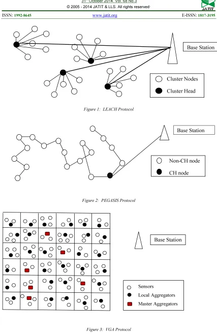
This protocol forms clusters considering the distance to BS and a Cluster Head is chosen for every cluster in a random fashion. The non Cluster Head nodes that are engaged in transmission sense the data and send those data to the Cluster Head. The data gets aggregated and then are forwarded to the sink node. The principle is that energy get uniformly distributed throughout the network as different nodes are selected as the cluster-head periodically.The Figure 1 shows the working of LEACH protocol.
In each round to form the cluster, network is made to follow the two steps to select
Cluster Head and to transfer the aggregated data.
(1) Set-Up Phase, which is again subdivided in to Advertisement, Cluster Set-Up & Schedule Creation phases (2) Steady-State Phase, which provides data transmission using Time Division Multiple Access (TDMA) [6]. Every round is generally divided into set up phase and steady state phase. In the set up phase, all the nodes in the Wireless Sensor Network generates a random value between 0 and 1, the threshold T(n) is defined. The condition is if the random value of the node is larger than the threshold. If the node has not been chosen as the Cluster Head in former 1/P rounds, satisfying the above said conditions only then the node can become the next Cluster Head [6].
[ p/(1-p)] * [r mod(1/p)] if nƐG T(n) =
0 otherwise
The threshold of T(n) is defined as
p -> expected percentage to become the CH. r -> current round
G -> nodes that has not been the CH for the previous 1/P round.
The Cluster Head collects and
aggregates information from the sensors in the same cluster and passes on information to the destination node through the other Cluster Head. By rotating the cluster-head randomly, energy consumption is expected to be uniformly distributed. LEACH includes distributed cluster formation , local processing to reduce global communication and randomized rotation of the Cluster Heads. LEACH performs local data fusion to compress the amount of data being sent from the cluster to the BS. Reduces energy dissipation and enhances system lifetime. [26] However, LEACH considers all the nodes in the clusters to have identical amount of energy and rotates CH in random manner. So there is a possibility of lower energy node to turn out to be a Cluster Head which results in reducing the lifetime of the entire network.
Properties of LEACH protocol
Cluster based
Random selection of Cluster Head in
rotation
Cluster is chosen based on nodes having
utmost energy.
Aggregating data at Cluster Head
(around).
Adaptive cluster members.
Cluster Head communicate via sink
node or user.
Utilizes TDMA.
4.2 PEGASIS Protocol
greedy algorithm. The BS can compute this chain and broadcast it to all the sensor nodes [13].
Assuming all the nodes has global knowledge of the network, construct the chain using the greedy algorithm. This approach to construct the chain work well and this is done before the first round of the communication. To construct the chain, we begin with the farthest node from the BS. In order to confirm that node farther from the BS have close neighbours we begin with this node. In the greedy algorithm the neighbour distance will increase gradually as nodes on the chain cannot be revisited. The Figure 2 explains PEGASIS protocol.
4.3 VGA Protocol
Virtual Grid Architecture (VGA) is an energy efficient routing paradigm. A hierarchical model that utilizes data aggregation and in network processing at two levels at the network hierarchy. This is done in order to extend the network lifetime. The node is stationary and with low mobility in many applications in the Wireless Sensor Networks, this is a reasonable approach to arrange nodes in a fixed topology. An approach which is GPS free build clusters that are equal, fixed, adjacent, non overlapping with symmetric shapes. To obtain a fixed rectilinear virtual topology square clusters are used. In each zone, a node is selected to act as its Cluster Head. Data Aggregation is performed locally and globally. The set of CH’ s are also called as Local aggregators (LA), performs local aggregation, a subset of these LA’s are used to perform global aggregation. To determine the optimal selection of global aggregation points, Master Aggregators (MA) is employed. The BS is not necessarily located at the extreme corner of the grid, it can be located at any arbitrary place [14]. Figure 3 explains the working of VGA protocol which was drawn from [5].
In general, the data dissemination process can be done properly by applying those mentioned clustering algorithms. Particularly in PEGASIS, each sensor node just forwards the data to the neighbour and the last node prior to the BS will transmit data directly to the Base
Station (BS). However in LEACH the Cluster Head selection process done routinely and each node getting chance to act as the CH. In this paper, by changing certain parameters in the routing algorithm we are obtaining various LEACH enhancements and probably the better performances can be achieved. The following table describes the highlighted features of the LEACH algorithm compared with others
Table 1 shows a comparison between LEACH, PEGASIS, and VGA routing protocols. The main characteristics of the hierarchical clustering protocols are distinct [17].
Even though PEGASIS and VGA performs better than LEACH. PEGASIS and VGA can be applied to larger networks. Data aggregation is possible in LEACH whereas PEGASIS forms a linear network and also
PEGASIS does not follow hierarchical
clustering. When the LEACH protocol is modified with certain parameters, all the new concepts bring better results. In order to extend the network lifetime the VGA can be applied for certain circumstances. This approach can be used in GPS free build clusters that are equal, adjacent and non-overlapping with symmetric shapes. In each zone an arbitrary is selected to act as the CH. However, the network lifetime can be extended and the additional overhead might be introduced during data aggregation. To overcome the additional Over Head we are changing few parameters like Cluster Formation, Cluster Head selection techniques (Modifying the fashion of election) and Energy level in the nodes of traditional LEACH and the results shows the extended features.
5. DESCENDENTS DERIVED FROM LEACH
5.1 Cell-Leach
In the Cell-LEACH the sensor network is divided into sections called as cell. A cell will encompass several sensors inside it. In each cell a sensor is chosen as the Cell Head. Seven cells together form a cluster and that cluster has a Cluster Head. Clustering process and celling process will be functioning as long as the network is alive, only the Cell Heads and the Cluster Heads changes. Cell Head in each cell will allocate a limit of time based on the TDM (Time Division Multiplexing) to sensor nodes. Within the designated time, each cell should transfer its data to the Cell Head. The same technique is used for transferring data from Cell Head to Cluster Head. When transmitting data, except the nodes that are slicing time all the other nodes will be made to remain in off mode. The redundant information is either deleted or aggregate the data in the Cell Head received from different sources [8]. After this process those information will be sent to the Cluster
Heads. Figure 4 illustrates Cell-LEACH
protocol.
5.2 Leach - C ( Centralized Leach)
The algorithm is based on centralized clustering .The steady state is the same whether in the set up phase each node sends information about the current location and also the energy level of the BS . Using the global information of the network it produces better clustering that requires the less energy for data transmission. To track the location either it requires the GPS or any other location tracking method .The Base Station must be made to check that only the nodes with enough energy is allowed to participate in the selection of CH. The BS is made to broadcast the information to all the nodes in the network [18].
LEACH-C has an algorithm which determines the amount of energy in the node and checks whether the node was elected as a CH or not. The nodes that has been elected as the CH
and its placement cannot be guaranteed .The central CH control algorithm is used to form the clusters which may produce better clustering through the distribution of the CH all over the network in a widespread fashion [8]. LEACH-C is explained in the Figure 5.
5.3 Leach-F (Fixed No. Of Clusters)
In LEACH-F, once the clusters are formed there is no overhead at the beginning of each round i and they are fixed. The same C- LEACH is used for cluster formation algorithm. In this algorithm, new nodes cannot be added to the system. The proposed new protocol cannot handle the new mobility. The Cluster Head position is alone rotated among the nodes inside the cluster. A stable cluster and rotating Cluster Head is used in LEACH-F, here once the cluster is formed it is maintained through the network lifetime. This avoids the reclustering [11].
5.4 Leach -E (Energy)
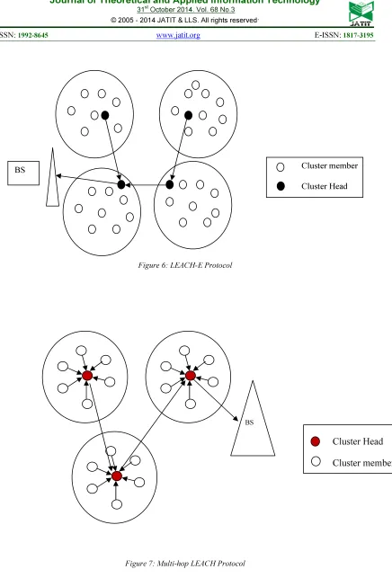
It gets operated using the Cluster Head selection algorithm where the nodes have non-uniform energy levels at the time of start. All the sensor nodes have the global information about all other sensor nodes. To minimize the total energy consumption, the required amount of CH has to scale as the square root of the total number of sensor nodes. LEACH-E is used to determine the above. Considering the residual energy of the sensor nodes as the main parameter, the nodes are checked whether it is eligible to become a CH in the next round [2]. Figure 6 illustrates LEACH-E protocol.
5.5 Leach-L
Clusters are made to reestablish in each round consisting of the setup phase and the steady state phase. In each round new CH are elected and the load gets distributed and balanced in the
network
.
5.6 Multi Hop Leach
The distance between the CH and the BS is increased enormously when the network diameter is increased beyond a certain limit the LEACH which is not possible. In such case the multihop communication is employed in order to obtain an energy efficient protocol. Multi hop LEACH is a completely distributed clustering based. This multi hop approach is used both inside and outside the cluster [24]. Multi-hop LEACH is explained in the Figure 7.
5.7 Two Level Leach (Tl-Leach)
In LEACH protocol, the CH collects and aggregates data from the sensor in its own cluster. The information is passed to the BS directly. The distance between the BS and the CH might be very high. So, the CH uses most of its energy for transmission. This is because the CH is always in on mode and the CH will die faster than other nodes. In this protocol, CH collects data from other clusters and works as of the traditional LEACH but transfers data directly to BS. It uses one of the CH’s that is lying between the CH and the BS as a relay station [20]. Figure 8 explains TL-LEACH protocol.
5.8 Leach-S (Solar Aware Centralized Leach)
In LEACH-S the BS selects the CH using the improved central control algorithm BS selects solar powered nodes having maximum residual energy. In this protocol each and every node sends the solar status to the BS. The nodes with higher energy levels are selected as the CH [29]. When the number of solar aware nodes are increased the performance of the WSN is increased. The sun duration increases the lifetime of the sensor network [10]. Solaraware-LEACH is explained in the Figure 9. In the solar aware
LEACH protocol the solar panel connected nodes gets more chance to become the Cluster Head. As the solar powered nodes has more energy it is always available to become the Cluster Head. It is found to be having enough energy to become the next Cluster Head in the forth coming rounds. Even though in the previous round if the node becomes completely exhausted as the system is connected with a Solar panel it is always ready to be the next Cluster Head after 1/P rounds energizing themselves automatically.
Figure 9: Solaraware- LEACH Protocol
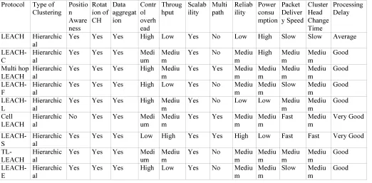
The Table 2 shown below explains the characteristics of LEACH protocol and the descendent of LEACH protocols. The tabulation clearly explains that the modified LEACH is better than the conventional LEACH protocol in atleast one aspect.
6. SIMULATION DESIGN:
Here the Simulation is done using Network Simulator-2 and the best improved descendent protocol of LEACH protocol named Solar aware protocol (LEACH-S) [10] among the other protocols performs the best in terms of energy consumption, throughput, overhead node and alive rate even after many rounds. Increasing all these will enhance overall lifetime of the network. The performance of the network is
calculated using the lifetime of the network, this
means it is calculated starting from the simulation till the last node dies. As the energy in the nodes gets depleted and nodes die at a
particular time this energy consumption is a
good parameter to rate the performance of the system. Assuming that the nodes in the network are distributed randomly inside a square region the simulation is performed. The Base Station is fixed and is located at the centre of the region.
Solar Panel
Sensor
Table 3:Simulation Parameters
Simulation Area 200*200
Nodes in number 100
Size of each packet 4000bits
Energy in each node 1 joule
Cluster Head proportion p=6%
Base Station location 100,100
Number of nodes with 1.5 joules energy 5% Number of nodes with Solar Panel connected 5%
7. RESULTS:
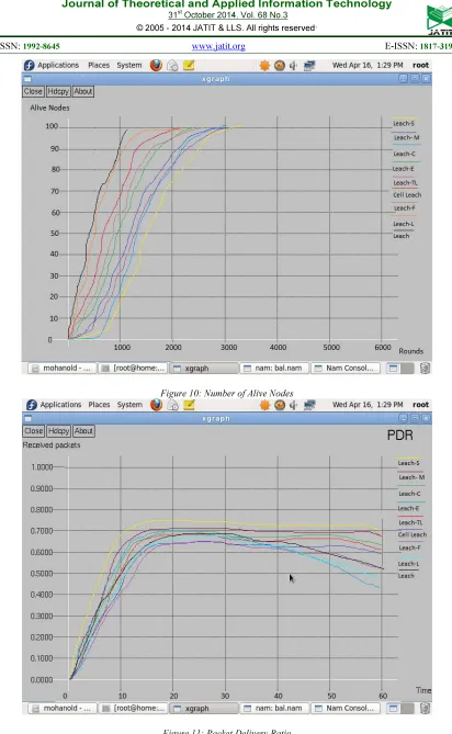
Figure 10 shows the sensor node’s alive rate. This graph is drawn between alive nodes vs Number of rounds. Results show that the normal LEACH performs the least and LEACH-S (Solar aware) performs the best. Similarly, Figure 11 shows the Packet Delivery Ratio (PDR). This is plotted between Packets delivered vs time. The Solar aware LEACH performs best than LEACH and its other descendents.
8.CONCLUSION
The Solar aware sensor nodes in the Solar aware centralized LEACH is more efficient as the nodes are connected with a solar cell. If the energy gets depleted immediately the nodes get recharged. Solar energy is always available in plenty and the nodes are given maximum guarantee that they are alive for longer period of time whether the nodes are stationary or dynamic. Even Though the Cluster Heads are selected in random fashion in LEACH, nodes are connected with a solar panel for efficient energy utilization. This is more helpful for the Cluster Head that is over burdened. After a while, if the same node is earning the chance to become the next Cluster Head after a round it can perform without any setback as the node would have got energized.
The simulation results show that the solar aware LEACH protocol performs better in terms of the nodes life rate. The nodes are found
to be prolonging their lifetime. Since the nodes are extending their lifetime, the overhead in the WSN gets reduced drastically increasing the packet delivery ratio. In future the LEACH enhancement can be achieved by applying soft computing approaches.
REFERENCES
[1]Chi-Tsun Cheng, Chi K. Tse, C. M. Lau “A
Clustering Algorithm for Wireless Sensor Networks Based on Social Insect Colonies” 2010 IEEE
[2]VinayKumar, Sanjeev Jain and Sudharshan Tiwari, IEEE Member,” Energy Efficient Clustering Algorithms in Wireless Sensor
Networks: A Survey”,IJCSI International
Journal of Computer Science Issues,
Vol.8,Issue 4,No 2,September
2011,ISSN(Online): 1694-0814
[3]Heinzelman W.B.,Chandrakasan
A.P.,BalakrishnanH.,”An application specific protocol architecture for wireless microsensor
networks,” IEEE Trans on Wireless
Communications,Vol 1,No
4,2002,pp.660-670,doi: 10.1103/TWC.2002.804190
[4] M. Younis, M. Youssef and K. Arisha, “Energy-Aware Routing in Cluster-Based
Sensor Networks”, in the Proceedings of the
10th IEEE/ACM(MASCOTS2002), Fort
Worth, TX, October 2002
[5] http://alkautsarpens.wordpress.com/WSN/ [6] Chenmin Li , Guoping Tan , Jingyu Wu , Zhen
Zhang , Lizhong Xu “Analyzing Cluster-head Selection Mechanisms and Improving the
LEACH ” 2011 IEEE
[7] Jia Xu,Ning Jin, Xizhong Lou,Ting Peng,Qian Zhou,Yanmin Chen “Improvement
of LEACH protocol for WSN” 2012 IEEE
[8] Arezoo Yektaparast, Fatemeh-Hoda Nabavi, Adel Sarmast “An Improvement on LEACH Protocol (Cell-LEACH) ”
[9] J. N. Al-Karaki, and G. A. Al-Mashaqbeh, “SENSORIA: A New Simulation Platform
for Wireless Sensor Networks”, International
[10] ThiemoVoigt,HartmuttRitter,Jochen Schiller, Adam Dunkels, and Juan
Alonso,”Solar-aware Clustering in Wireless Sensor
Networks”,In Proceedings of the Ninth IEEE
Symposium on Computers and
Communications,June 2004.
[11] K. Khamforoosh, and H. Khamforoush, “A new routing Algorithm for Energy Reduction
in Wireless Sensor Networks”, IEEE, 2009
[12] J.N Al-Karaki, and A.E. Kamal, “Routing techniques in wireless sensor networks: a
survey”, IEEE Wireless Communications,
Vol. 11, No. 6, pp.6-28, December 2004. [13] S. Lindsay and C. Raghavendra, “PEGASIS:
Power-Efficient Gathering in Sensor
Information Systems”, International Conf. on
Communications, 2001.
[14] J.N Al-karaki et al.,”Data Aggregation in Wireless Sensor Networks – Exact and
Approximate Algorithms,” Proc. IEEE Wks.
High Perf. Switching and Routing 2004,
Phoenix, AZ, Apr. 18-21, 2004.
[15] Chi-Tsun Cheng, Chi K. Tse and Francis C. M. Lau “A Delay-Aware Data Collection Network Structure for Wireless Sensor
Networks” 2011 IEEE
[16] Wu Xinhua and Huang Li” Research and Improvement of the LEACH Protocol to Reduce the Marginalization of Cluster Head” Journal of Wuhan University of Technology Vol.35, No.1, Feb.2011, pp.79- 82,
[17] R. V. Biradar, V. C. Patil, Dr. S. Sawant, and Dr.R.R. Mudholkar, “Classification and comparison of routing protocols in wireless
sensor networks”, UbiCC Journal, Vol. 4.
[18] X.H.Wu,S. Wang, “Performance comparison of LEACH and LEACH-C protocols by
NS-2,” Proceedings of 9th International
Symposium on Distributed Computing and Applications to Business, Engineering and
Science. Hong Kong, China, pp
254-258,2010.
[19] Arezoo Yektaparast, Fatemeh-Hoda Nabavi, Adel Sarmast “An Improvement on LEACH Protocol (Cell-LEACH) ”
[20] M. Bani Yassein, A. Al-zou'bi, Y. Khamayseh, W. Mardini “Improvement on
LEACH Protocol of Wireless Sensor
Network (VLEACH)” International Journal
of Digital Content Technology and its
Applications Volume 3, Number 2, June
2009.
[21] P.T.V.Bhuvaneshwari and V.Vaidehi”
Enhancement techniques incorporated in
LEACH- a survey” Department of
Electronics Engineering Madras Institute
Technology, Anna University
Chennai,India,2009
[22] Tao,L,Zhu,QX,Zhang,L.An Improvement for LEACH Algorithm in Wireless Sensor
Network.Proc.5th IEEE Conf.Indust.Electr.
Appl.2010;1:1811-4.
[23]RajashreeV.Biradar,Dr.S.R.Sawant,Dr.R.
R.Mudholkar, Dr.V.C.Patil” Multihop
Routing In Self-Organizing Wireless Sensor
Networks” IJCSI International Journal of
Computer Science Issues,Vol.8,Issue
1,January 2011
[24] Hwa Young Lim, Sung Soo Kim, Hyun Jun Yeo, Seung Woon Kim and Kwang Seon Ahn “ Maximum Energy Routing Protocol based on Strong Head in Wireless Sensor Networks
” IEEE 2007
[25] S.K.Singh,M.P. Singh, and D.K.Singh,”A Survey of Energy-Efficient Hierarchical Cluster-based Routing in Wireless Sensor
Networks,” International Journal of
Advanced Networking and
Application(IJANA), Sept-Oct, 2010,
vol,02,issue 02,pp 570-580.
[26]W.Heinzelman, A.Chandrakasan and
H.Balakrishnan,”Energy-efficient routing
protocols
for wireless micro sensor networks,” in Proc.
33rdHawaii Int. Conf. System
Sciences(HICSS), Maui, HI,Jan.2000.
[27] Laiali Almazaydeh, Eman Abdelfattah, Manal Al- Bzoor, and Amer Al- Rahayfeh” Performance Evaluation of Routing Protocols
in Wireless Sensor Networks” International
Journal of Computer Science and Information
Technology, Volume 2, Number 2, April
2010, pp 64-73.
[28] Ravneet Kaur, Deepika Sharma and Navdeep Kaur, “Comparative Analysis Of Leach And Its Descendant Protocols In Wireless Sensor
Network” International Journal of P2P
Network Trends and Technology-
[29]J.Gnanambigai, Dr.N.Rengarajan, K.Anbukkarasi ” Leach and Its Descendant
Protocols: A Survey ”International Journal of
Figure 1: LEACH Protocol
[image:11.595.84.511.85.742.2]Figure 2: PEGASIS Protocol
Figure 3: VGA Protocol
Cluster Nodes
Cluster Head
Base Station
Non-CH node
CH node
Base Station
Base Station
Sensors
Local Aggregators
Table 1: Comparison of Hierarchical Clustering Protocols
Routing Protocol
Category Data Disseminatio n
Scalability Overhead Data Delivery Fashion
Energy Utilization
Network Performance
LEACH Hierarchical Yes Good High CH based High Good
PEGASIS Hierarchical Yes Good Less Chain Based Medium Very Good
VGA Hierarchical Yes Good High Good Low Good
Figure 4: Cell LEACH Protocol
Figure 5: LEACH-C Protocol
Cluster Head
Sensor nodes
BS
Cluster Head
Sensor Nodes
[image:12.595.61.538.147.242.2]Figure 6: LEACH-E Protocol
Figure 7: Multi-hop LEACH Protocol
Cluster member
Cluster Head BS
Cluster Head
Cluster members
Figure 8: Two Level (TL) LEACH Protocol
Table 2 Comparison of LEACH and its Descendents
Protocol Type of Clustering Positio n Aware ness Rotat ion of CH Data aggregat ion Contr ol overh ead Throug hput Scalab ility Multi path Reliab ility Power consu mption Packet Deliver y Speed Cluster Head Change Time Processing Delay
LEACH Hierarchic
al
Yes Yes Yes High Low Yes No Low High Slow Slow Average
LEACH-C
Hierarchic al
Yes Yes Yes Medi
um
Mediu m
Yes No Mediu
m
High Mediu
m Mediu m Good Multi hop LEACH Hierarchic al
Yes Yes Yes High Mediu
m
Yes Yes Mediu
m Mediu m Mediu m Mediu m Good LEACH-F Hierarchic al
Yes Yes Yes High Low Yes No Mediu
m
Mediu m
Slow Mediu
m Good LEACH-L Hierarchic al
Yes Yes Yes High Mediu
m
Yes No Low Low Mediu
m Mediu m Good Cell LEACH Hierarchic al
No Yes Yes Medi
um
Mediu m
Yes Yes Mediu
m
Mediu m
Fast Mediu
m Very Good LEACH-S Hierarchic al
Yes Yes Yes Low High Yes Yes High Low Fast Fast Very Good
TL-LEACH
Hierarchic al
Yes Yes Yes Medi
um
Mediu m
Yes No Mediu
m Mediu m Mediu m Mediu m Good LEACH-E Hierarchic al
Yes Yes Yes High Low Yes No Mediu
m
Mediu m
Slow Mediu
m
Good
CH1
CH1b
SN5
SN3 SN4
SN1 SN2
[image:14.595.41.563.439.696.2]Figure 10: Number of Alive Nodes