© 2017, IRJET | Impact Factor value: 5.181 | ISO 9001:2008 Certified Journal | Page 699
Review of Effect of Tool Nose Radius on Cutting Force and Surface
Roughness
Vaykhinde Akash S.
1, Bhor Ulhas B.
2, Sachhe Vaibhav V.
3, Valte Samrat P.
4,
Asst. Prof. S. B. Deokar
51BE Student, Department of Mechanical Engineering, SND COE & RC, Maharashtra, India 2BE Student, Department of Mechanical Engineering, SND COE & RC, Maharashtra, India 3BE Student, Department of Mechanical Engineering, SND COE & RC, Maharashtra, India 4BE Student, Department of Mechanical Engineering, SND COE & RC, Maharashtra, India 5 Asst. Professor, Department of Mechanical Engineering, SND COE & RC, Maharashtra, India
---***---Abstract –
Machining is most important and commonprocess in manufacturing. Various different types of cutting tool are used for cutting the different metals. There is a different type of cutting tool like single point cutting tool and multi-point cutting tool. Rake angle, flank angle, nose radius and other tool geometry are the different parameters of single point cutting point tool. The main effect on metal cutting is by rake angle, clearance angle, and nose radius. The nose radius having more effect on the surface roughness and cutting force. Feed rate also having the identical effect on the cutting force and surface roughness. Nose radius and cutting force and feed force are directly proportional and nose radius increases surface roughness is indirectly proportional.
In this paper, the various forces such as cutting force, feed force and the axial force have been found out with the variation in depth of cut for EN8 materials. Graphs are drawn on how these forces vary with the variation in the depth of cut. The cutting force during turning is measured by using two-dimensional tool dynamometer and surface roughness is measured by using profilometer.
Key Words:Tool nose radius, tool dynamometer, cutting
force, surface roughness.
1. INTRODUCTION
In metal turning process, for achieving certain shape, layer, size and surface quality of work piece for cutting tool required. There are many type of cutting tool
developed to satisfy the requirement production for smooth running. The dimensions and shapes of work piece either determine by graphically and analytically during design. For greater productivity there are many researches are carried for decrease production cost and increase quality. There are many cutting parameter as follows:
i. Rake angle ii. Depth of cut iii. Feed rate iv. Cutting speed
In machining process there are twp type of method are implemented.To determine the effects of the parameters although most of the cutting processes are oblique, orthogonal cutting techniques are used in experiments of two dimensional mechanical workpiece. Important factors like cutting speed, tool rigidity and depth of cut, feed rate and tool geometry are determining the behavior of machinability of mechanical workpiece.
1.1 Types of Cutting Tools 1. Single point cutting tool
2. Multi-point cutting tool 1. Single point cutting tool-
Single point cutting tool has only one cutting
© 2017, IRJET | Impact Factor value: 5.181 | ISO 9001:2008 Certified Journal | Page 700 boring, turning, shaping, facing this tool is used on a
various machine like lathe machine, boring machine, shaper planer, etc.
Fig-1: Features of a single point tool
1.2 The various cutting parameters i. Nose radius
ii. Rack angle iii. Depth of cut iv. Feed rate
v. Cutting speed vi. Cutting force vii. Surface roughness
i.Nose radius: Nose radius is joint of side and end cutting edges by means of small radius by this increased life of the tool and better.
ii.Rack angle: It is the angle between normal to the finished surface in a plane perpendicular to the cutting edge.
iii.Depth of cut: It is the volume of work piece material that can be removed by the machining process. iv.Feed rate: It is the velocity of tool to the machining
process.
v.Cutting speed: It is relative speed between the surface of work piece and cutting tool.
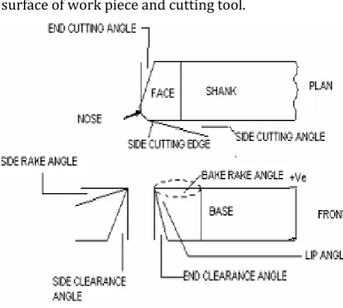
Fig -2: Various parts of single point cutting tool
1.3 Types of metal cutting process
Classification of metal cutting process
a) Orthogonal cutting process (Two-dimensional cutting)
b) Oblique cutting process (Three-dimensional cutting)
a) Orthogonal Cutting: The cutting edge of the tool is perpendicular to the work piece axis.
b) Oblique Cutting: The cutting edge is inclined at an acute angle with normal to the cutting velocity vector is called oblique cutting process
1.4 Tool Life
The time elapsed between two consecutive tool reshaping is called tool life. During this period the tool works effectively and efficiently.
Taylor’s Tool Life Equation Vtn = C
[image:2.595.316.567.122.347.2] [image:2.595.46.297.163.324.2]© 2017, IRJET | Impact Factor value: 5.181 | ISO 9001:2008 Certified Journal | Page 701 V = Cutting speed in M/Min
n = Index depends upon tool and work C = Constant
1.4.1 The Ways of Representing Tool Life Some of the ways of expressing tool life: 1. Time unit
2. Volume of metal removed expressing tool life 3. Number of work piece machined per grind 1.4.2 The Factors Affecting Tool Life 1. Feed and depth of cut
2. Cutting speed 3. Tool material 4. Tool geometry 5. Work material 6. Cutting fluid
7. Rigidity of work, tool and machine
2. AIM AND OBJECTIVE OF WORK
Nose radius is a parameter used in various cutting and machining process. Describing the angle of cutting face. In tool geometry selection of tool nose radius is not an independent variable in process because the effect of tool nose radius depends on cutting tool geometry and cutting process.
The aim and objective of this study are as follows 1. To study the influence of nose radius on metal
turning process.
2. To evaluate cutting force.
3. To find tool wear and decrease it. 4. To decreases residual stresses.
3. LITERATURE REVIEW
Y. Kevin Chou et al. 2004 [1] The tool nose radius effects is examined by finish turning of hardened AISI 52100 sheets of steel. The different conditions like
© 2017, IRJET | Impact Factor value: 5.181 | ISO 9001:2008 Certified Journal | Page 702 which leads to economical machining and improved
productivity.
J. Naga Malleswara Rao et al. 2010 [3] In this experiment new type of dynamometer to measure radial of a component of cutting force using strain gauges. Dynamometer is used to measure the cutting force in any metal cutting process. The working principle of dynamometer is calibrated and readings are obtained and specimen is tested for performance. It is mostly used in roller burnishing process on aluminum work piece under various conditions in rollers burnishing process, a hard roller is pressed against a rotating cylindrical work piece and parallel to the axis of the work piece on lathe. From different lubricant applications in roller burnishing operation Optimum values of burnishing force and the corresponding surface roughness value (Ra) are obtained. This dynamometer can be manufactured at a low cost. This dynamometer can be used for tests on lathe in metal cutting laboratories and engineering colleges. Variation in depth of cut can’t influence of the corner radius on the cutting forces.
B.Tulasiramarao1 et al. 2014 [4]The cutting force can be measure by Research focusing on a lathe tool dynamometer, thrust/Axial force and also feed force by using strain gauge accelerometer has been Studied. The dynamometer applied in this experiment is a 500kg force 3-component system. To a data acquisition system the dynamometer is to be connected. When the tool comes in contact with the work piece the different forces are produces and they can capture and transformed into numerical form system. In these experiment different forces for four various materials
and the materials used in this project are aluminum, brass; mild steel & nylon have been noted down. The variation in depth of cut is studied by the forces on these different materials with it. Forces vary due to variation in depth of cut are shown by Graphical representation.
Moaz H. Ali et al. 2014 [5] In this work, they are focusing to use a wide range of tools and techniques to ensure that the designs they are created it saves. Sometimes accidents happen when they are work in the laboratories or factories. To know success industries need to know whether a product failed or how much percentage need.
4. CONCLUSIONS
After reviewing much paper related to nose radius, rack angle, feed rate etc. They can be affected the cutting force and surface roughness from above study it is clear that tool nose radius is a most important parameter in single cutting point tool. The result obtaining from the various literature surveys the following conclusion is state-
1. As a nose radius may be increased then effect on cutting force also get increases.
2. Surface roughness gets decreases with respect to increasing in nose radius.
3. Increase in feed rate can also increase the surface roughness.
ACKNOWLEDGEMENT
© 2017, IRJET | Impact Factor value: 5.181 | ISO 9001:2008 Certified Journal | Page 703 We would also like to thank our internal guide
Asst. Prof. S. B. Deokar Department of Mechanical Engineering, for his valuable encouragement and constant scrutiny without which we wouldn’t have looked deeper into our work and realized both our shortcomings and our feats. This work would not have been possible without him.
REFERENCES
[1] Y. Kevin Chou, Hui Song, Tool nose radius effects on finish hard turning, Journal of Materials Processing Technology 148, 2004, pp. 259–268. [2] Maheshwari Patil, Dr. R. J. Patil, Study Effect of HSS
Single Point Cutting Tool Nose Radius on Cutting Edge Strength and Tool Wear in Machining of EN9, International Journal of Science and Research (IJSR), 12, December 2014, Volume 3, pp. 2563- 2567.
[3] J. Naga Malleswara Rao, A. Chenna Kesava Reddy and P.V. Rama Ra, Design and fabrication of new type of dynamometer to measure radial component of cutting force and experimental investigation of optimum burnishing force in roller burnishing process, Indian Journal of Science and Technology, July 2010, Vol. 3 No. 7.
[4] B. Tulasiramarao, Dr. K. Srinivas, Dr. P Ram Reddy, A.Raveendra and Dr. B. V. R. Ravi Kumar, Finding Cutting Forces While Turning Aperation on Lathe Machine at Different Depth of Cut of Different Metals, International Journal of Innovative Research in Science, Engineering and Technology, oct 2014, Vol. 3 pp. 16867-16872.
[5] Moaz H. Ali, M. N. M. Ansari, The Effect of Nose Radius on Cutting Force and Temperature during Machining Titanium Alloy (Ti-6Al-4V),