Http://www.ijetmr.com©International Journal of Engineering Technologies and Management Research [194]
ANALYSIS OF A MODIFIED GROUND PLANE MICROSTRIP PATCH
ANTENNA USING CO-AXIAL FEED
Rahul Tiwari 1, Dr. Ashish Bagwari 2, Dr. Vivek Singh Kushwah 3, Abhishek Senger 4 1
Department of Electronics and Communication, Medi-Caps University Indore, India 2
Department of Electronics and Communication, WIT, UTU, Dehradun, India 3
Department of Electronics and Communication, Amity University, Gwalior, India 4
Department of Electronics and Communication, ATC, Indore, India Abstract:
A wandered probe-fed rectangular microstrip patch antenna (RMPA) with rectangular slots on a finite ground plane with dielectric material substrate (4.4) is proposed in this paper. The proposed antenna finite ground plane dimension is only 18mm x 21mm. The simulated result shows two distinct resonant frequencies at 4.5 and 9.5 GHz. A 10-dB wide-impedance bandwidth of 1000 MHz and 4100 MHz ranging from 3.8-4.8 GHz and 5.9–10 GHz is achieved. The proposed antennas have achieved wider bandwidth (51.3%) with reasonable
gain (4 dBi).
Keywords: Rectangular Microstrip Patches Antenna (Rmpa); Rectangular Slot; Ground Plane; Ie3d Software.
Cite This Article:Rahul Tiwari, Dr. Ashish Bagwari, Dr. Vivek Singh Kushwah, and Abhishek Senger. (2018). “ANALYSIS OF A MODIFIED GROUND PLANE MICROSTRIP PATCH ANTENNA USING CO-AXIAL FEED.” International Journal of Engineering Technologies and Management Research, 5(2:SE), 194-200. 10.29121/ijetmr.v5.i2.2018.644.
1. Introduction
Http://www.ijetmr.com©International Journal of Engineering Technologies and Management Research [195] 2. Design A Proposed Antenna Using Introducing Slot in Ground Plane
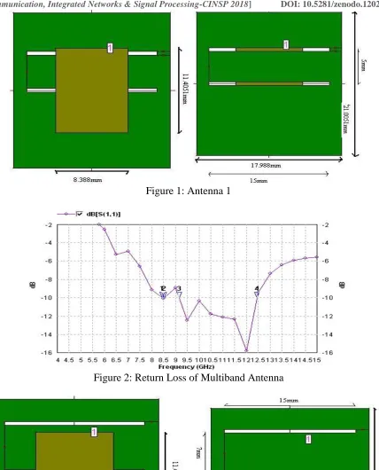
The widely popular, method-of-moments-based electromagnetic (EM) software for high-performance network distributed simulation and optimization (IE3D) tool is used for the design and simulation of the proposed antenna. Like other typical patch antennas, the proposed antenna contains probe feed connector on its side, a meandered structure probe feed the radiating part, a rectangular type radiating surface introduced with slot line of the same width on top and a rectangular ground plane at the bottom [4-5].
Table 1: Specifications of the Microstrip Patch Antenna [7] Magnitude Unit
Dielectric Constant (єr) 4.4 -
Loss Tangent (tan ∂) 0.002 -
Thickness (h) 1.6 mm
Operating Frequency 8 GHz
Length (Lp) 8.3 mm
Width (Wp) 11. 4 mm
Ground Length (Lg) 18 mm
Ground Width (Wg) 21 mm
Feed Coaxial Feed -
After designing the conventional microstrip patch antenna, Introducing slots (parametric study) in the ground plane of the antenna is used for design a compact rectangular microstrip patch antenna for the C-band and X-band, which may be useful for the current miniaturized wireless communication system. This modified proposed antenna to have characteristics of wideband operation, enhance bandwidth, along with reducing the size and meandered gain. These modifications include the introducing of slots in the ground plane. These slots, when accordingly designed to the dimensions of the slot by hit and trial rule and increase the current path within the patch area. These help in lowering the resonant frequency of the microstrip patch antenna and, therefore, lead to size-reduction as well as enhance the bandwidth [7-8].
3. Simulate A Proposed Antenna Using Electromagnetic Simulation Software IE3D
Http://www.ijetmr.com©International Journal of Engineering Technologies and Management Research [196] Figure 1: Antenna 1
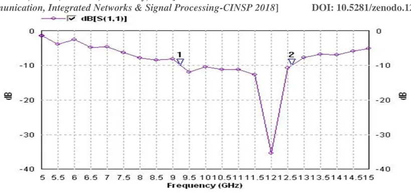
Figure 2: Return Loss of Multiband Antenna
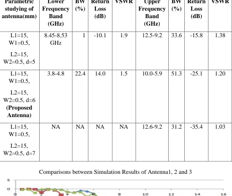
Http://www.ijetmr.com©International Journal of Engineering Technologies and Management Research [197] Figure 4: Graph of Return loss of wideband RMPA
Figure 5: Upper Layer and Ground Layer Antenna 3
Http://www.ijetmr.com©International Journal of Engineering Technologies and Management Research [198] Table 2: Simulated Results of the Antenna by parametric studying of The Dimension of
Ground-Plane Slots Parametric studying of antenna(mm) Lower Frequency Band (GHz) BW (%) Return Loss (dB)
VSWR Upper
Frequency Band (GHz) BW (%) Return Loss (dB) VSWR L1=15, W1=0.5, L2=15, W2=0.5, d=5 8.45-8.53 GHz
1 -10.1 1.9 12.5-9.2 33.6 -15.8 1.38
L1=15, W1=0.5, L2=15, W2=0.5, d=6 (Proposed Antenna)
3.8-4.8 22.4 14.0 1.5 10.0-5.9 51.3 -25.1 1.20
L1=15, W1=0.5,
L2=15, W2=0.5, d=7
NA NA NA NA 12.6-9.2 31.2 -35.4 1.03
Comparisons between Simulation Results of Antenna1, 2 and 3
4. Discussion of Results
Http://www.ijetmr.com©International Journal of Engineering Technologies and Management Research [199] experimental that, the −10 dB impedance bandwidth of the projected RMPA 1, 2 and 3. This alignment and parametric revision have been approved out by the support of the commercially existing IE3D simulator, and a respectable agreement is observed in the simulated results.
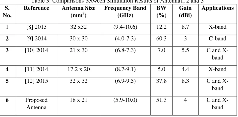
Table 3: Comparisons between Simulation Results of Antenna1, 2 and 3 S.
No.
Reference Antenna Size (mm2)
Frequency Band (GHz) BW (%) Gain (dBi) Applications
1 [8] 2013 32 x32 (9.4-10.6) 12.2 8.7 X-band
2 [9] 2014 30 x 30 (4.0-7.3) 60.3 3 C-band
3 [10] 2014 21 x 30 (6.8-7.3) 7.0 5.5 C and
X-band
4 [11] 2014 17.2 x 20 (8.7-9.1) 5.0 4.4 X-band
5 [12] 2015 32 x 32 (6.9-9.5) 37.8 8.3 C and
X-band
6 Proposed
Antenna
18 x 21 (5.9-10.0) 51.3 4 C and
X-band
5. Conclusion
The proposed compact RMPA with modified ground plane is presented in this paper. The simulated results show that the proposed antennas have achieved wider bandwidth (51.3%) with reasonable gain (4 dBi). The Miniaturized antenna is designed for the ranging from 3.8-4.8 GHz and 5.9–10.0 GHz which include C-band and partial X-band. The accurate simulation results are obtained. In future, the antenna needs to be fabricated and tested.
References
[1] A. Balanis, “Antenna Theory, Analysis and Design,” John Wiley & Sons, New York, 1997. [2] B. Ahamadi, R. F. Dana, “A miniaturised monopole antenna for ultra-wideband applications with
band notch filter,” IET Microwave antennas Propagations, vol.3, 2009, pp.1224-123.
[3] Chen, W. L., G. M. Wang, and C. X. Zhang, “Bandwidth enhancement of a microstrip line fed printed wide-slot antenna with a fractal shaped slot,” IEEE Transactions on Antennas Propagation, Vol. 57, No. 7, 2176-2179,2009.
[4] A.A. Deshmukh, K.P. Ray, “Compact Broadband Slotted Rectangular Microstrip Antenna,” Published in IEEE Antennas and Wireless Propagation Letters, 2009.
[5] Kim, H., and C.-W. Jung, “Bandwidth enhancement of CPW fed tapered slot antenna with multi transformation characteristics,” Electronics Letters, Vol. 46, No. 15, 1050-1051, 2010.
[6] Trang Dang Nguyen, Dong Hyun Lee, and Hyun Chang Park, “Design and Analysis of Compact Printed Triple Band-Notched UWB Antenna,” IEEE Antennas And Wireless Propagation Letters, Vol. 10, 2011.
Http://www.ijetmr.com©International Journal of Engineering Technologies and Management Research [200] Plane,” International Journal of Computer Applications Volume 29 Number 1(ISBN: 978-93-80864-72-0) 1-4, September 2011.
[8] Abhishek, K., R. Sharma, and S. Kumar, “Bandwidth enhancement using the Z-shaped defected ground structure for a microstrip antenna,” Microwave and Optical Technology Letters, Vol. 55, 2251-2254, 2013.
[9] Rawat, S. and K. K. Sharma, “A compact broadband microstrip patch antenna with a defected ground structure for C-band applications,” Central European Journal of Engineering, Vol. 4, 287-292, 2014.
[10] Mourad, M. and M. Essaaidi, “A dual ultra-wideband slotted antenna for C and X-band application,” Progress In Electromagnetics Research Letters, Vol. 47, 91-96, 2014.
[11] Samsuzzaman, M. and M.T. Islam, “Inverted S-shaped compact antenna X-band applications,” The Scientific World Journal, Vol. 14, 1-11, 2014.
[12] Rahul Tiwari, Seema Verma, and Archana Sharma, “Proposed a compact multiband and broadband rectangular microstrip patch antenna for C-band and X-band,” International Journal of Computer and Technology, vol. 13, no. 3, pp. 4293-4301, April 2014.
[13] Nivedita Girase, Rahul Tiwari, Archana Sharma and Hema Singh, “Design and simulation of slotted rectangular microstrip patch antenna,” International Journal of Computer Applications, vol. 103, no.17, pp. 19-23, October 2014.
[14] Jamshed A. Ansari, Sapna Verma, Mahesh K. Verma and Neelesh Agrawal, “A Novel Wide Band Microstrip-Line-Fed Antenna with Defected Ground for CP Operation,” Progress In Electromagnetics Research C, Vol. 58, 169-181, 2015.
[15] Rahul Tiwari, Seema Verma, and Archana Sharma, “Design and analysis of multi-band rectangular microstrip patch antenna for C band and X band applications,” International Journal of Scientific & Engineering Research, vol. 6, issue 10, October-2015.
[16] Rahul Tiwari, Seema Verma, Archana Sharma and Ashok Kumar, “Design and analysis of a compact microstrip antenna using shorting pin for 5 GHz band,” IEEE International conference on computer, communications and electronics, 1-2 July 2017.
*Corresponding author.
![Table 1: Specifications of the Microstrip Patch Antenna [7] Magnitude Unit](https://thumb-us.123doks.com/thumbv2/123dok_us/8977542.1886910/2.612.182.437.209.453/table-specifications-microstrip-patch-antenna-magnitude-unit.webp)