Accepted Manuscript
An Aspect-Oriented, Model-Driven Approach to Functional Hardware Verifi‐
cation
Eamonn Linehan, Siobhán Clarke
PII:
S1383-7621(11)00018-X
DOI:
10.1016/j.sysarc.2011.02.001
Reference:
SYSARC 999
To appear in:
Journal of Systems Architecture
Received Date:
30 June 2010
Revised Date:
20 December 2010
Accepted Date:
4 February 2011
Please cite this article as: E. Linehan, S. Clarke, An Aspect-Oriented, Model-Driven Approach to Functional
Hardware Verification,
Journal of Systems Architecture
(2011), doi:
10.1016/j.sysarc.2011.02.001
An Aspect-Oriented, Model-Driven Approach to
Functional Hardware Verification
IEamonn Linehan, Siobh´an Clarke
Lero - The Irish Software Engineering Research Centre, Distributed Systems Group, School of Computer Science and Statistics, Trinity College Dublin, Ireland
Abstract
The cost of correcting errors in the design of an embedded system’s hardware components can be higher than for its software components, making it important to test as early as possible. Testing hardware components before they are imple-mented involves verifying the design through either formal or more commonly, simulation-based functional verification. Performing functional verification of a hardware design requires software-based simulators and verification testbenches. However, the increasing complexity of embedded systems is contributing to test-benches that are progressively more difficult to understand, maintain, extend and reuse across projects. This paper presents an aspect-oriented
domain-specific modelling language for the e hardware verification language that can
be used as part of a model-based software engineering process. The modelling
language is designed to produce well modularised models from which e code
can be generated, thereby improving engineers ability to develop testbenches that can be more easily maintained, adapted and reused. We demonstrate the suitability of the modelling language through its application to a representative testbench from the automotive semiconductor industry.
Keywords: Model-Based Software Engineering, Aspect-Oriented
Programming, Theme/UML, Code Generation, MARTE, DSML, Hardware Verification
1. Introduction
Embedded systems are engineering artifacts that involve computation that is subject to physical constraints [1]. In our daily lives, we are surrounded by countless examples of embedded systems. For instance, vehicles contain tens of electronic components (control units, sensors, and actuators) that perform tasks
IThis work was supported, in part, by Science Foundation Ireland grant 03/CE2/I303 1
to Lero - the Irish Software Engineering Research Centre (www.lero.ie)
Email addresses: [email protected](Eamonn Linehan),
ranging from the control of mechanical aspects of the vehicle, such as engine management, anti-lock brake system, suspension and transmission, to tasks such as communication, navigation, and entertainment [2]. Similarly, our homes and workplaces are full electronic devices. Such embedded systems require a high level of reliability. Consequently, the process of developing such systems and rigorously verifying their behaviour is critical [3].
Embedded systems are typically realised as a combination of both hardware and software. The hardware elements range from a single microcontroller to systems containing multiple processing units, peripherals and networks. Recent advances in design automation and semiconductor manufacturing have resulted in the potential to build increasingly complicated systems that consequently are difficult to develop and test. The development process for the hardware components of such systems is constrained by a need to test early because of the increased cost of correcting bugs after hardware has gone into production [4]. The accepted practice is to test before implementation by performing functional verification of the design [2].
In the case of embedded systems that are realised in hardware, Bergeron reported that 70% of system design time is spent on verification [5], while in 2007, Li et al. asserted that up to 80% of design costs in many circuit de-sign projects are due to verification [6]. The primary method of functional verification of hardware is to perform dynamic, simulation-based verification using testbenches written in domain specific verification languages [7]. These
languages include, VHDL, Verilog, e and OpenVera [8], but may also include
external data files or C routines [5].
The growing complexity of verification environments can be attributed to the increased state space of more complex hardware designs [9]. In fact, it has been shown that verification complexity rises exponentially with hardware complexity [10]. In embedded systems design, this problem is commonly referred to as the ‘productivity gap’. As complexity grows, the productivity gap is the difference between hardware capacity and engineering output [11]. With such a large proportion of design time spent on verification, reducing the productivity gap requires verification engineers to: 1) increase the reusability of hardware verification testbenches; and 2) work at higher levels of abstraction.
There have been a number of recent efforts to address the problem of reuse-ability in functional hardware verification [12, 13]. However, reusing verification IP is challenging, not least because of incompatible methodologies from single vendors targeting single verification environments, poorly documented verifica-tion code and a need to customise verificaverifica-tion code provided by third parties. In addition, many testbenches have evolved over years, developed by different teams at different sites, with many layers of new functionality added over a period of time, with knowledge lost along the way through incomplete docu-mentation [14].
a logic gate made of transistors) using a model where some low-level details are ignored. By applying this approach, digital electronic design went from drawing layouts, to transistor schematics, logic gate netlists and ultimately to today’s register transfer level (RTL) descriptions [2]. Similarly, verification engineers have used hardware environments that have evolved from low level C libraries to aspect and object-oriented domain specific languages for the verification of RTL designs with built in support for functional coverage measurement, constrained random generation and other verification-specific functionality. However, the volume and complexity of code is increasing, methodologies and development process do not take full advantage of the power of these languages and the use of programming paradigms unfamiliar to hardware engineers hampers their ability to understand, maintain, extend and reuse code across projects.
Modelling is gaining popularity as an approach to the design of complex systems, raising the level of abstraction at which developers work, promising improved quality and increased productivity through automation. A model is an abstract representation of a system, often diagrammatic in nature. Models are widely used as part of the design process of safety critical embedded sys-tems to provide insights into the dynamics and algorithmic aspects of syssys-tems through simulation [4]. These simulation models undergo test and verification before designs are implemented. The increased state space of complex hardware designs means that the software-intensive verification process is also increasing in complexity. Despite this, the design of verification environments has benefited little from the use of modelling techniques and hence has seen little application
of developments in the area of model-driven engineering1[15]. This is partly due
to the difficulty in creating adequate models with support for concurrency, real-time requirements and physical properties of continuous functioning computing platforms using standard object-oriented modelling techniques [16, 17].
Current modelling languages do not contain properties and modelling con-structs targeting the hardware verification domain. Concepts such as, coverage, constrained random generation, assertion checking, simulation time and inter-acting with a design under test are absent from modelling languages targeting other domains. In addition, many of these properties are verification concerns that cut across the structure and behaviour of functional concerns.
This paper presents a domain-specific modelling language for theehardware
verification language that can be used as part of a model-driven engineering
toolset for embedded systems development. The e language is chosen as a
representative verification language because of its feature set and wide use in
industry. Theemodelling language metamodel is implemented as an extension
to UML, incorporating aspect-oriented constructs from Theme/UML [18] and design and verification constructs from MARTE [19] to help engineers organise code in a way that makes it easy to deal with the concerns they really care
1Model-driven engineering is a design approach where systems are specified as models.
about in a verification environment [20]. Our model-driven approach is designed
to produce well modularised, cleanly decomposed models from which e code
can be generated, thereby improving engineers ability to develop testbenches that can be more easily maintained, adapted and reused. Providing for aspect-oriented design at the model level makes it possible to integrate with and directly reuse existing testbenches, providing a migration path to facilitate adoption of a model-based software engineering process.
The rest of the paper is structured as follows. Section 2 provides background on the typical embedded system hardware development and verification process
and tools and describes theehardware verification language. Section 3 presents
the UML2 profile for theeverification language illustrating how it can be used
to model hardware verification testbenches and Section 4 describes an example
where a testbench is designed using theeprofile and source code is generated.
Section 5 summarises related work while Section 6 concludes the paper and outlines plans for future work.
2. Background
To provide a sufficient context and terminology for our discussion on mod-elling languages for hardware verification, we start by presenting some back-ground on verification methods and hardware verification languages.
2.1. Functional Verification Testbenches
Verification of hardware designs can be performed dynamically based on sim-ulation, or statically based on formal techniques. In the automotive industry it is common to use both approaches, formal techniques where safety is important and simulation for the complete design as it provides coverage metrics that give the designers some assurance that the complete design state space has been exercised.
This paper concerns itself with the modelling of verification languages for the dynamic, simulation-based verification of hardware designs. Simulation-based verification is currently the primary method for functional verification of hardware and system-level designs [9]. It consists of providing input stimuli to the Design Under Test (DUT), and checking the correctness of the output response. The success of simulation has largely been due to automation through development of testbenches, which provide the verification context for a DUT.
The large proportion of design time consumed puts verification on the critical path of a design process that is increasing in complexity and cost [21]. In addition, the majority of design flaws are functional or logic related (78% and increasing) and current design processes and tools are achieving a first silicon success of only 28% with a downward trend [22]. These factors compound each other resulting in significant design challenges in building functional verification testbenches [1].
Figure 1: Typical Hardware Design and Verification Process.
a hardware description language. The verification phase consists of designing a testbench architecture and implementing the testbenches and a set of testcases. Executing the testbench against a simulated design verifies the functional cor-rectness of the hardware design [23, 24].
Architecturally, a typical testbench consists of a generator of input stimuli, a checker or monitor for checking output response and a coverage analyser. In addition, depending on the component being verified, portions of the system may be simulated as part of the testbench to address issues related to system-level integration and the effects of distributed concurrent computation (for example, data buses). The testbench development process can involve many engineers with limited cross-over between teams writing verification testbenches and teams implementing the design.
2.2. Hardware Verification Languages
Functional verification testbenches are typically written in domain specific
verification languages such as VHDL, Verilog, e and OpenVera [8], but may
form pseudo-random test generation. The e hardware verification language is
one such domain-specific programming language that was developed in 1997 by Verisity Design (subsequently acquired by Cadence Design Systems [25]) as part
of their Specman tool [26]. ewas standardised as IEEE 1647 [27] and a second
revision of the standard was published in 2008.
This paper adopts e as the verification language on which to base a
do-main specific modelling language so that familiar verification constructs could be carried over into the modelling language, making it easier for verification en-gineers to adopt modelling as part of their development process and ultimately
to transition to a model-driven development process. In addition, e is a
flex-ible language with growing tool support [8] and is used by our collaborators in the automotive semiconductor industry, providing a source of early industry feedback on our work. By initially focusing on a single verification language it is possible to support current development techniques in terms of design and verification language, reducing the burden of learning a new set of tools and languages [28].
In providing support for the development of testbenches,e brings together
concepts from several languages [29] and
• has a basic object-oriented (OO) programming model with automatic
memory management and single inheritance in a similar manner to Java;
• uses native constructs to modularise concerns that cut across others using
aspects;
• supports constraints as object features, using constraints to refine object
models. The execution model resolves the constraints, picking random values that satisfy the constraint set;
• is strongly typed, like Pascal and Modula;
• has concurrency constructs for hierarchical composition, similar to
hard-ware description languages such as Verilog and VHDL; and
• contains temporal logic constructs that borrow from linear temporal logic
and interval temporal logic.
As a testbench language,eprovides many constructs related to stimuli
gen-eration, such as specification of input constraints and facilities for data packing, as well as for assessing simulation coverage. All variables are assigned a random value unless either marked as not generatable or constrained to be a specific
value. econtains constructs that support monitoring and checking the response
of the DUT. In addition, there are constructs to support assessment of the functional coverage of the DUT (as opposed to simply the code coverage).
3. An Aspect-Oriented Model-Driven Approach
This paper presents a modelling language for theehardware verification
for embedded systems development, raising the level of abstraction at which de-velopers work, promising improved quality and increased productivity.
Model-based software engineering (MBSE)2 is an approach to software development
that focuses on the production of high-level models that are used as the ba-sis for automating system implementation. The fundamental notions behind MBSE are to raise the level of abstraction of software specifications away from underlying implementation technologies and to automate the transition from design specifications to corresponding implementations [30].
3.1. Aspect-Oriented Design
The e hardware verification language (and Vera 6.2+) supports
aspect-oriented constructs, which must therefore be supported by modelling tools. Be-fore we present the design of our domain-specific modelling language, we provide
a brief introduction to aspect-oriented design and modelling3in the context of its
improvements in support for modularisation over the object-oriented paradigm. Object-Oriented Programming (OOP) offers a “separation of concerns” that allows designers to break down a program into distinct parts. Each of these parts, be they classes, packages, components, etc., are designed to encapsulate all the code related to a single concern. However, object-oriented decomposition results in developers having to work on many concerns at once as secondary concerns crosscut the primary decomposition resulting in modules that overlap in functionality. Allan et. al. presented a simple example of a single task from a class used to manage a DMA controller [33]. In his example, he showed how code for tracing the execution of the program, handling errors, checking input and accessing shared resources was scattered throughout the code dealing with the tasks intended function. The code dealing directly with the task’s intended function is referred to as the dominant concern and the remaining code belongs to secondary cross-cutting concerns.
Aspect-Oriented Programming (AOP) offers a new construct, an aspect, that can be used to encapsulate these crosscutting concerns in a way that minimises the overlap in functionality between modules [31]. Dominant concerns are coded using OOP as before and aspects are used to code cross-cutting concerns and integrate them with the dominant concerns. Studies have shown that AOP improves the degree to which crosscutting concerns are separated in software, improving maintainability and developer productivity [34, 35, 36].
The AOP features of thee language give it the power to significantly
sim-plify and accelerate the development of reusable, automated, verification
envi-ronments [20]. However, aspect-based techniques in eare rarely considered at
design time as a way of modularising code. Instead, aspect-oriented features
2The termsmodel-driven development,model-driven engineeringandmodel-driven
archi-tecturerefer roughly to the same software engineering approach and are used interchangeably in the literature, though model-driven architecture generally refers to OMG’s standards-based approach.
3See Kiczales et. al. for description of aspect-oriented programming [31] and Gomes et.
in eare often used to add new features to existing code without having to
in-trusively modify the code base. This can, in part, be attributed to published methodologies [37, 26], verification IP [38, 13, 12], tutorials [39, 40] and best practice guidelines [41] on testbenches design from industry.
Reasoning about decomposition becomes simpler at higher levels of ab-straction [42]. For this reason the aspect-oriented paradigm, when applied at the model level and with the existing support of underlying verification lan-guages, can contribute to a more productive functional verification process. It has been reported that hardware verification testbenches lend themselves to aspect-oriented design as they commonly contain concerns that cannot be cleanly modularised with object-oriented methods alone [43, 33, 17, 44]. Fur-thermore, aspect-oriented design complements the MBSE approach by facili-tating the partitioning of models along aspect boundaries, providing a single view of each concern. However, integrating MBSE and AOP requires modelling conventions for expressing crosscutting concerns at the model level. This pa-per presents a verification testbench modelling language based on extensions to Theme/UML, an aspect-oriented modelling language [18].
3.2. Model-Driven Theme/UML
Theme/UML facilitates graphical modeling of concerns in an extended ver-sion of UML, the object-oriented analysis and design language from the Object Management Group. Theme/UML add constructs including a new type of clas-sifier called a theme and three integration strategies - merge, bind and override, to UML. These UML constructs are implemented as a UML2 profile, facilitating the tagging of UML models with information that indicates where functionality belongs to an aspect and how aspects are related to each other. The theme construct is based on the standard UML package and encapsulates the design specification of a base or aspect concern. Base themes are modelled using the standard UML process and any of the available diagram types. An aspect theme is one that encapsulates a crosscutting concern and is designed relative to ab-stract templates. In the current version of Theme/UML, sequence diagrams are used to specify when and how the templates interact with the base themes.
Theme/UML supports compositional constructs to cater for both overlap-ping and crosscutting relationships between themes. A merge integration strat-egy is used between two or more themes to produce a single theme containing
the union of the merged themes. Abind integration strategy facilitates
compo-sition of aspect themes with base themese.g., specification of how cross-cutting
embedded systems concerns are composed with core functional concerns. Bind composition relationships relate aspect themes template operations to triggering base operations by means of a sequence diagram. The third kind of integration
strategy is calledoverride and deals specifically with overlapping specifications
where the design specification of one theme is denoted to override that of an-other.
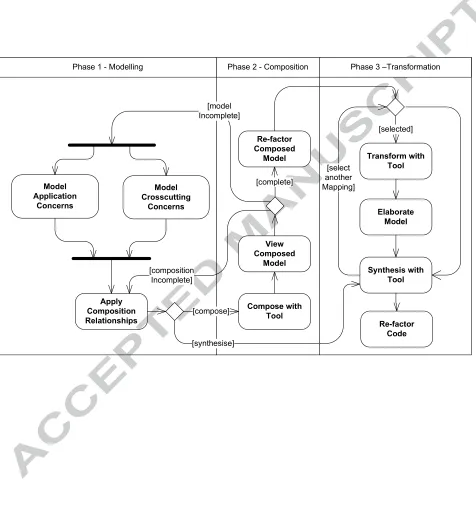
Figure 2: Model-Driven Theme/UML Process
code [45]. The tool suite and process was originally designed to support devel-opment of applications for deployment on smartphones but has been extended to support transformations to other embedded software platforms by offering synthesis to C code [46]. Figure 2 illustrates the Model-Driven Theme/UML development process. The process contains three distinct phases that are titled based on the activities of the developer during each phase.
The first phase involves system modelling via specification of base concerns, aspect concerns and composition relationships in Theme/UML. The second phase involves composition of the models specified during the modelling phase to produce a composed, platform-independent standard UML view of the system. The transformation phase performs a template-based model-to-text transforma-tion using an open code generatransforma-tion technology called Xpand, part of the Eclipse
Modelling, Model To Text Project4.
In collaboration with Infineon Technologies, we have analysed the challenges in modeling hardware verification environments, using the Theme/UML MBSE
process [14]. Theme/UML is a natural fit to modeling e testbenches because
of its aspect-oriented approach. However, when applied to verification, the ex-tended Model-Driven Theme/UML approach has been found to be deficient in a number of areas. Specifically, temporal concerns, runtime constrained com-position, constraints and type extension could not be easily modelled. This
paper contributes, a new profile for the e verification language that supports
aspect-oriented design using Theme/UML and a model-based software engi-neering process based on the model-driven Theme/UML process and tools.
3.3. Modeling thee Language
This section presents theeUML2 profile, a collection of extensions that
col-lectively customise UML for the hardware verification domain. The following requirements have been identified for extensions to standard UML. These
re-quirements are derived from theelanguage reference model [27] and literature
on best practice in metamodel design [47, 48].
• Aspects: Aspect constructs in ehave different semantics than languages
like AspectJ. Theme/UML pointcuts are modelled when a theme template is bound to a set of triggers in the base themes. This method of specifying
aspect composition is more powerful than is required bye, which has only
three types of join point and permits only a single join point per advice.
• Modularity: The e language does not impose strict rules on how aspect
and object-oriented code should be packaged. The modelling language should enforce its own packaging rules to organise code so that aspects and object-oriented code can be easily navigated and to facilitate the mapping from aspects to files as proposed by Robinson, [20, pg. 75, chap. 3].
• Reuse: It is required that lightweight metamodelling approach is taken to
allow the reuse and specialisation of existing profiles. This will also reduce the effort required to build and integrate a consistent toolchain for MBSE.
• Type System: Support must be provided for scalar sub-types. These types
are created ineusing a scalar modifier to specify the range or bit width of
a scalar type. In addition, these modifiers can be applied to enumerated scalar types.
• Encapsulation: There are two types of object in e, a struct and a unit.
Structs roughly correspond to objects in other programming languages and units differ in that they are bound to a component in the DUT.
• Inheritance: Two types of inheritance must be supported,like andwhen.
Like inheritance is the classical single inheritance familiar to users of all
object-oriented languages. When inheritance is a concept unique toeand
is specified by defining sub-types with when struct members, supporting multiple orthogonal sub-types based on field values.
• Physical Fields; Fields can be either physical or virtual. Physical fields
• Behaviour: Operations can be time consuming or non-time consuming.
Time consuming operations are triggered by events that are defined based on a simulator clock.
• Concurrency: Behavioural actions exist to control concurrent execution of
time-consuming methods.
• Constraints: Constraints define the legal values of data items. There are
two basic types of constraints: Hard constraints must be met or an error is issued; Soft constraints suggest default values but can be overridden by hard constraints.
• Events: The e language provides temporal constructs for specifying and
verifying behavior over time. Alletemporal language features depend on
the occurrence of events, which are used to synchronise activity within the simulation environment.
• Temporal Behaviour: The environment interprets and guarantees
tempo-ral behaviour rules. These rules are also used to define events based on simulator clocks and must be modelled.
• Coverage: Coverage groups are struct members that contain a list of data
items for which data is collected over time. This data is analysed by developers to determine design coverage for tests.
• Simulation Constructs; Verification languages typically expose a simulator
interface through constructs built into the language.
• Pre-defined Elements; Theeverification language contains a range of
pre-defined types, structs, events and error handlers which must be modelled.
The domain specific abstractions, highlighted in our requirements, have been implemented as extensions in a UML2 profile. Profiles are UML’s mechanism for lightweight extension where each extension of an element from the UML2 metamodel is captured by a stereotype. Each stereotype definition can be asso-ciated with properties that make sense for the domain targeted by the profile. Stereotypes are then used at the modeling level as annotations on model ele-ments.
A systematic approach was taken to the design of theeUML2 profile.
Fol-lowing advice from the literature [48], we used the e reference model [29] as
conceptual model from which entities could be extracted and transformed into
stereotypes. For example, the reference model defines e constructs as
belong-ing to categories that determine how the constructs can be used. Examples of
these categories are Struct Members and Actions with Struct Members being
constructs that are contained within a Struct such as, fields, methods,
sub-types, constraints, coverage and temporal declaration. Our modelling language
includes aStruct stereotype that is an extension of the UML2Class metaclass.
e_ProfileRelationships ie.lero.tcd.e
package [ ]
´«profile´»
e
´«profile´»
Verilog
´«profile´»
VHDL
MARTE_AnalysisModel MARTE_DesignModel MARTE_Foundations MARTE_Annexes
´«profile´»
MARTE
override explicit merge
theme bind
´«profile´»
ThemeUML
´«profile´»
VSL
´«profile´»
Time
Figure 3: UML Profile Relationships
by a containment relationship. Struct members that represent concepts that do
not already exist in the UML2Classelement (the parent of theStructelement)
are defined as stereotypes inheriting from theStructMember stereotype.
Other e specific constructs, such as, field parameters are defined as tags
(stereotype properties). For example, e supports parameters (i.e. physical or
generated) that can be attached to fields to indicate how the fields interact with the simulation environment during verification. These parameters are modelled
as attributes of theStructMember stereotype.
TheeUML2 profile inherits features from both Theme/UML and the OMG
UML profile for Modeling and Analysis of Real-time and Embedded systems (MARTE) [19]. MARTE is a UML profile that supports specification of real-time and embedded systems. In addition to functional design, this profile adds constructs to describe the hardware and software (for example, OS services) resources and defines specific properties to enable designers to perform timing and power consumption analysis. MARTE packages features into individual sub-profiles allowing one to import only the parts of the profile that are required.
Theeprofile extends and reuses elements from theTime andValue
Specifi-cation Language (VSL)(See Figure 3). These constructs are reused to specify constructs such as concurrency and synchronisation and to attach quality
at-tributes and model simulator clocks. For example, the MARTE TimeEvent
stereotype from the Time sub-profile is used as a basis for modellinge events
for defining constructs to represente’s time consuming methods. From the VSL
sub-profile we have reused MARTE’s IntervalType to define scalar data type
range modifiers ine.
Theeprofile itself is divided into three packages: theCore package contains
model elements corresponding to e language constructs; the Verilog package;
and the VHDL package contain simulation related constructs (statements or
unit members that expose functionality simulator).ie.lero.tcd.e e_CodeOrganisation
package [ ]
-physical : boolean -assignDefaultValue : boolean -const : boolean -ungenerated : boolean -keepConstraint : String -keepSoft : boolean
´«stereotype´» e::Field [Property] ´«stereotype´» e::PreprocessorDirective [Element]
-isEmpty : boolean = false ´«stereotype´»
e::Method
[Operation] -ownedCover : Cover [0..*]
-ownedEvent : Event [0..*] ´«stereotype´» e::Struct [Class] -template ´«stereotype´» ThemeUML::theme [Package]
-empty : Boolean = false ´«stereotype´» e::Cover [NamedElement] ´«stereotype´» e::ExtendableElement [Element] ´«stereotype´» e::Event [NamedElement]
-definition : String ´«stereotype´»
e::IfDef
[Element]
-hdl_path : String ´«stereotype´» e::Unit [Class] ´«stereotype´» e::StructMember [NamedElement] -element-type ´«stereotype´» e::Port [NamedElement]
-type : Field ´«stereotype´» e::CoverItem [NamedElement] ´«stereotype´» e::Module [Package] ´«stereotype´» e::Manifest [Package] ´«metaclass´» Element ´«metaclass´» Package -definition * -event-type 1 -members 0..* Import * 0..*
Figure 4:eProfile Aspect-Oriented Elements
Figure 4 illustrates some of the core UML extensions in the profile5. Classes
with thee:: prefix belong to the e profile. The main structural entity in the
profile is e::Module, an extension to ThemeUML::theme which in turn is an
extension to theuml:PackageUML 2.0 metamodel element. Thee::Moduleclass
represents a block of verification logic that belongs in a single file. Modules can encapsulate a single aspect or a collection of object-oriented structures and are
related to each other usingimportrelationships. Other key structural elements
of the profile includee::Struct ande::Unit, each of which have a corresponding
abstract stereotype definition that groups their members. For example,e::Struct
has an abstracte::StructMember stereotype that is realised by elements such as
5The complete UML2 profile is available for download from our websitehttp://www.lero.
e::Event, e::Cover, e::Operation and e::Field. Where a member is extendable
by an aspect it inherits from the e::ExtendableElement stereotype, indicating
that this element can be used as a join point.
ie.lero.tcd.e
package [ e_AOP ]
-struct-subtype : String ´«stereotype´»
e::Extend
[Dependency] -binding
´«stereotype´»
ThemeUML::bind
[Dependency]
-aspect -base
´«interaction´»
IsAlso
(e.AdviceType)
-aspect -base
´«interaction´»
IsFirst
(e.AdviceType)
-aspect -base
´«interaction´»
IsOnly
(e.AdviceType) ´«metaclass´»
Dependency ´«metaclass´» Interaction
Supports conditional aspect-oriented extension using Theme/UML composition relationship and specified behaviour (Default IsAlso) -advice_type 1
Figure 5: The definition of e UML2 Profile aspect-oriented constructs as extensions to
Theme/UML.
Figure 5 illustrates how the Theme/UML profile is reused and extended
to support e’s aspect-oriented constructs. Theme/UML’s profile extends the
UML 2.0 metamodeluml::Dependency class to add abind attribute. This new
relationship is intended to model a bind relationship between base and aspect
themes. Theeprofile further refines theThemeUML::bindstereotype by
extend-ing it with thee::Extend stereotype. This stereotype models an aspect-oriented
extension and has two attributes, thestruct subtype to support conditional
ex-tension and anadvice type attribute of type uml::Interaction. The profile
in-cludes three predefineduml::Interactioninstance that model the possible advice
types ine. Figure 6 shows the sequence diagram for one of these instances of
uml::Interaction,isFirst.
( source : Operation, target : Operation )
interaction IsFirst [ IsFirst ]
aspect base
source 2:
target 3:
return 5:
return 4: target
1:
Figure 6: Sequence diagram for interactionisFirst
for modelling the aspect-oriented constructs ofe. To use Theme/UML directly
without this extension would require composition behaviour to be specified in a unique sequence diagram for every piece of advice. The one to one mapping
from advice to join points in e would result in many diagrams, limiting the
scalability of the approach.
Figure 7 illustrates how a developer would apply these aspect-oriented
con-cepts to a UML model using theeprofile. In this example two modules contain
objects that are related through an aspect-oriented extension. In this case the pkt msg()operation in the base modulesPacket object is extended by the
method of the same name in the eth module using the isFirst advice type.
This construct should be interpreted as, at runtime, thepky msg()behaviour in
theeth module should be executed before the pky msg()behaviour in the core
module. A more complex example of this behaviour is illustrated in Section 4. The following modifications to Theme/UML are specified to facilitate the
modelling of the aspect-oriented constructs ine:
1. Composition relationships are represented by curved, dashed lines between elements to be composed. All composition relationships are directional with theme precedence being inferred from relationships direction. 2. Override integration must be specified explicitly in the same way as merge
integration.
3. Each element named in a match composition must appear in both modules and be of the same type.
4. Matching elements in a composition are specified as part of the compo-sition using a list syntax (similar to template and binding specification) that supports multiple element specification using groups and wildcards.
5. Theme composition relationship is extended to incorporate anadvice type
tag that specifies and instance of auml::Interaction.
Theeprofile also includes alle’s primitive datatypes, to which thee::ScalarModifier
´«Module´» eth
´«Field´»-proto_version : int ´«Field´»-virtual_channel_identifier : int
´«Method´»+pkt_msg() ´«Method´»+checksum() ´«Method´»+run()
´«Struct´»
Packet
{ownedCover = PacketCover } ´«Module´»
core
´«Field´»-kind : PacketKind
´«Method´»+pkt_msg() ´«Method´»+checksum() ´«Method´»+run()
´«Struct´»
Packet
{ownedCover = PacketCover }
´«Extend´» {advice_type = IsFirst ,
binding = "match[Packet.pkt_msg()]" }
´«Extend´» {advice_type = IsAlso , binding = "match[Packet.run()]" }
Figure 7: An example of applying aspect-oriented profile constructs.
supports the definition of lists of symbolic constants. LikeandWheninheritance
are modelled as stereotype extensions touml::Generalisation. Events are
mod-elled using thee::Event stereotype that supports the definition of a temporal
expression property. Coverage is modelled using thee::Cover stereotype. In
to-tal, the profile consists of 38 unique stereotypes grouped into three sub-profiles. Entities are referenced from Theme/UML, MARTE and UML.
In addition to the stereotypes provided by theeprofile, there are a number
of required elements of verification environments that need to be modelled. These elements are contained within a UML model library as instances of UML elements cannot be defined within a profile. This model acts as a template
for modellingeverification testbenches and contains predefined constants, error
handling operations, default struct hierarchy, simulator clock models and various flags and constants that are used by the language and need to be referenced by models of verification environments.
4. Application
To assess the applicability of the eprofile to testbench development we
makes use of constrained random generation to verify the operation of a pro-prietary bus protocol. Architecturally, the testbench is coverage-driven and consists of multiple master and slave end points connected to the DUT via a crossbar. The testbench is designed to work with Cadence’s Specman tool and interacts with a design modelled in VHDL. The goal is to explain the features
of theeUML2 profile through the implementation of a realistic testbench,
illus-trating how theeprofile facilitates testbench modularisation through separation
of concerns in design and automated source code generation.
Development began by analysing the sample testbench, extracting its main features. From these features, two sets of UML models were produced using a UML editor: models of the testbench itself; and models of the test cases which constrain the testbench behaviour to exercise particular features of the hardware design. The primary requirement for a UML editor is that it supports
the use of UML2 profiles and export to Eclipse Modelling Framework6 (EMF)
XML Metadata Interchange (XMI) format. Our current editor of choice is
MagicDraw 16.97, which is free under academic license. However, any UML
editor that supports integration of profiles and export to XMI can be used. To build the testbench models, the functionality was first divided into base or aspect concerns. In our case, because we were re-implementing a testbench for which source code existed, we could use aspect mining techniques such as clone detection and matching patterns of method calls to identify cross-cutting aspect concerns [50]. If implementing a testbench from scratch, it would be necessary to identify and group these concerns through an aspect-oriented analysis of the design [18].
In theeprofile, modules are based on Theme/UML themes and encapsulate
the specification of a base or aspect concern. Figure 8 shows how base themes
and aspect themes are designed by applying theModule stereotype defined in
thee profile to standard UML elements in the model. Cross-cutting modules
are indicated by a module dependency relationship with theExtendstereotype
applied. These aspect-oriented modelling constructs should be interpreted as
follows. In the case of thetb::Log module aDriver is defined with its
asso-ciated attributes and operations. TheExtendrelationship indicates that these
attributes and operations are merged with those of the Driver object in the
tb::Driver module. That is, the tb::Logmodule is an aspect that, through
identically named concepts, is composed with base classes in the tb::Driver
module.
This approach ensures that thetb::Logmodule contains only the structures
and behaviour necessary to represent the logging behaviour and thetb::Driver
module contains only elements related to managing input signals for theDUT.
This design illustrates how the crosscutting ReportHandlerconcern is cleanly
modularised within the single module as opposed to occurring repeatedly through-out the code.
´«Module´» tb::Application
-dut_signals : Signal [0..*]
+init() +setup() +run()
´«Unit´» Sri_Mif
-name : String -bus +write_beat() +read_beat() +init_agent() ´«Unit´» Agent
-master_signals : Signal [0..*] ´«Unit´» Sri_MasterAgent
-slave_signals : Signal [0..*] ´«Unit´» Sri_SlaveAgent
-address : unit -opcode -rw : Sri_Transfer -err_val : uint{numberOfBits = 8}
´«Struct´» Checking_Info ´«Module´» tb::Checker
-expect_data : byte [0..*] -scoreboard : Sri_Scoreboard -address_pipe : Sri_Transfer -data_pipe : Sri_Transfer
+check_addr_phase() +check_data_phase() +check_scoreboard_key() ´«Unit´» Checker +address_phase() +data_phase() ´«Unit´» Driver Protocol checkers omitted for brevity -log_name : String
-log_file : file
+open_file() +close_file() +write()
+log_trans( trans : Sri_Transfer ) ´«Unit´» Sri_Log ´«Module´» tb::Log +init() ´«Unit´» Sri_Mif
-log : Sri_Log
+address_phase() +data_phase()
´«Unit´» Driver
-beat_num -data : byte [32] -align_bursts : bool
+ready() +drive_transfer() +address_phase() +data_phase() ... ´«Unit´» Driver +encode() +decode() ´«Unit´» Entrophy_Decoder +run() ´«Unit´» Sri_Mif ´«Module´» tb::Driver -agents * -checker -checking_info -log -ed96 -driver ´«Extend´»
{advice_type = IsAlso } ´«Extend´»
{advice_type = IsAlso , binding = "match[name]"}
´«Extend´» {advice_type = IsAlso } ´«Extend´»
{advice_type = IsAlso , binding = "match[name]"}
Figure 8: An excerpt from the UML model of the testbench.
Whereas Figure 8 focuses on a portion of the generated model, Figure 9 illustrates the full set of unique modules developed for the testbench. The relationships between each module are included showing how aspect-oriented extensions are used to keep verification testbench components loosely coupled with respect to each other. These relationships dictate how the modules are composed to form a complete testbench and how the base modules are bound to the aspect modules that crosscut them. The design decisions required to produce this decomposition are based on work by Vax and Robinson who make a case for the use of aspect-oriented design in testbench development and present a method of organising concerns in a verification environment [20, 17].
Having built aspect-oriented models of the testbench in UML, the next step is to synthesise source code from this model. A code generation template has
been developed to perform code synthesis toe using a combination of Xpand
and a collection of custom Java extensions to the Xpand language8.
Figure 10 shows a snippet of the Xpand template designed to deal withWhen
inheritance relationships in UML models. The template uses references to types
defined as stereotypes in the eprofile to navigate the UML model outputting
code. TheEXPANDkeyword indicates that a template defined elsewhere should
be applied to the specified elements. In the example, theEXPANDcommand is
8Xpand is a language for code generation based on EMF models that is part of the eclipse
Xbar ´«Module´» Application NO_PREFETCH ´«Module´» Scoreboard ´«Module´» Monitor ´«Module´» Coverage ´«Module´» Clock ´«Module´» Log ´«Module´» Driver ´«Module´» Checker ´«Extend´»
{advice_type = IsAlso , binding = "match[name]" }
´«Extend´»
{advice_type = IsAlso }
´«Extend´»
{advice_type = IsAlso }
´«Extend´»
{advice_type = IsAlso }
´«Extend´»
{advice_type = IsAlso }
´«Extend´»
{advice_type = IsAlso , binding = "match[name]" }
´«Extend´»
{advice_type = IsAlso }
´«Extend´»
{advice_type = IsAlso }
´«Extend´»
{advice_type = IsAlso }
´«Extend´»
{advice_type = IsAlso }
´«Extend´»
{advice_type = IsAlso }
´«Extend´»
{advice_type = IsAlso , binding = "match[name]" }
´«Extend´»
{advice_type = IsAlso }
Figure 9: eUNL2 Profile showing full module composition diagram.
an instruction to apply the template namedOperations to all contained model
elements with thee::Method stereotype applied.
The code output by applying the Xpand template to a UML model developed
using theeUML2 profile extensions is illustrated in Figure 11. The UML models
resulted in eleven source code files being generated in theeverification language.
These files are organised in a package hierarchy that reflects the structure of the
emodel with each package containing many files and each file containing a single
emodule.
The testbench illustrates the main features of the e UML profile through
the re-implementation of a testbench that is in use in industry. The e profile
facilitates testbench modularisation through separation of concerns in design and automated source code generation. The aspect-oriented modelling approach is shown to ease the creation, maintainance and reuse of testbenches by making it possible to tackle common testbench scenarios that are not easily solved using OOP techniques alone [33].
5. Related Work
«IMPORT uml»
«IMPORT e»
«EXTENSIONmetamodel::Extensions»
«DEFINE StatementsFOR e::Struct»
«EXPAND CommentFOREACHtypeSelect(uml::Comment)-»
struct «name» {
«EXPANDFields FOREACH typeSelect(e::Field)-» «EXPANDOperations FOREACHtypeSelect(e::Method)-» «EXPANDWhenFOREACH getWhenInheritance()-»
};-- Endstruct «name»
«ENDDEFINE»
«DEFINE WhenFORe::When»when
«this.structsubtype» «getBaseStruct().name»{
«EXPAND OperationsFOREACH
getSpecificStruct().typeSelect(e::Method)»
};
«ENDDEFINE»
Figure 10: Snippet of the Xpandecode generation template.
The value in providing models of hardware verification environments at higher levels of abstraction was demonstrated by Gluska et. al. in the develop-ment of their pre-RTL model for verification [52]. They identified verification as being on the critical path of hardware development and demonstrated how abstract modelling of designs can shorten the verification process and enhance the effective use of coverage and formal verification techniques. However, the modelling taken was textual and did not consider reusability or modularity [52] There are a set of approaches that are capable of generating UML from ver-ification testbenches for the purpose of documenting their design. For example, the design and verification tools plugin (DVT) for eclipse by AMIQ [53] is ca-pable of extracting a UML class diagram illustrating a set of selected structs
from aneor SystemVerilog testbench. The purpose of this feature is to extract
a documenting UML model that shows inheritance, associations (pointers) and class members. Diagrammatically illustrating the structure of the testbench using a tool for drawing directed graphs reduces the time it takes engineers to become familiar with a new code base and helps manage naming and code navigation. However, the UML diagrams produced do not contain any
behav-ioural information and cannot capture the aspect-oriented constructs of thee
language, making the diagrams of little use for interpreting behaviour at run-time. The transformation from code to model cannot be reversed preventing any modifications of the class diagrams being reflected in the code.
Other work by Thompson et al. goes further than simply facilitating the generation of documentation and provides some support for code generation [54]. In this case code stubs for the verification language Vera are generated from class diagrams using UML to C++ code synthesis. However, the code skeletons then need to be modified by hand to remove C++ specific artefact’s and have their behaviour inserted. Because there is no Vera specific model, the transformations are not fully automated and cannot be reversed.
Figure 11: Generatedecode in eclipse.
real-time systems and informally specifying verification assertions at the model level. UML state diagrams are then transformed using an intermediate XMI representation to SystemVerilog code. Both structure and behaviour are speci-fied at the model level but the transformation is not reversible. McUmber at al. also make use of UML class and state diagrams to specify both structure and behaviour [28]. In their case VHDL specifications are generated by applying a set of rules for mapping from UML to VHDL.
[55]. However, TestBencher Pro’s timing diagram can only model a subset of the functionality required of a verification testbench.
The Embedded Systems Modeling Language (ESMoL), a language with sim-ilar capabilities to AADL [56], was proposed by Porter et. al. as part of a suite of domain-specific modeling languages for the design and verification of embed-ded systems [57]. However, ESMoL did not address the specific challenges of modelling functional verification of RTL designs. A similar high level modelling approach was demonstrated by Kukkala et. al. [58] who developed a UML 2.0 profile, called TUT-Profile, introducing a set of stereotypes and design rules for embedded system structural design. Numerous other projects define modelling languages for embedded systems [59, 60, 61]. However, none of these use UML2 profiles to address complexity and reuse issues of aspect-oriented hardware ver-ification testbenches.
Espinoza et. al. reference a number of projects that started recently and are working on modelling languages and tools for the design and verification of embedded systems [16]. The INTERESTED project is creating a tool-chain for rapid design and prototyping of embedded systems. The SATURN project is developing tools for architecture exploration, simulation and synthesis in Sys-temC/VHDL for hardware designs and the Lambda project intends to reconcile a number of related standards, including SysML, MARTE, AADL, and IP-XACT. These projects, yet to publish results, are not considering the use of aspect-oriented modelling to reduce design complexity by separating models into smaller more coherent pieces.
Although there has been some work in aspect-orientated and model-driven engineering of embedded systems [62, 5, 63, 32], these approaches can not be directly applied to hardware design and verification as languages in these ar-eas incorporate constructs that do not appear in general purpose high level languages (like C++ or Java). For example, constrained random stimulus gen-eration, temporal assertions and functional coverage constructs. Our profile for
hardware verification in theelanguage allows engineers to incorporate MBSE in
their existing design process by adopting a domain specific modelling language with familiar constructs.
6. Conclusion and Future Work
Model-based software engineering raises the level of abstraction at which de-velopers work, promising improved quality and increased productivity through automation. However, despite the increasing application of model-driven tech-nologies to the development of embedded systems, little attention has been paid to the corresponding larger increase in complexity of verification environments.
This paper has presented a new UML profile for theeverification language and a
testbenches that are less complex and easier to maintain and reuse. In addition,
theeprofile supportse’s aspect-oriented constructs, making it possible to
inte-grate with and directly reuse existing testbenches, providing a migration path to facilitate adoption of a model-based software engineering process. The MBSE
process supported by theeprofile contributes an ability to reduce development
time without sacraficing quality through automation.
A limitation of the current e profile is how close it is to the code level,
requiring a good knowledge of the e verification language. The extraction of
verification features and constructs that are common to all verification lan-guages into a higher level platform independent model will facilitate the design of verification testbenches at a higher level of abstraction and will eliminate the implementation and verification language specific features that are present
in the currente UML profile. This future work will further contribute to the
approaches ability to reduce design complexity and provide for the portability and reuse of test cases between various verification platforms.
It was also found that the approach of reusing elements from other UML profiles has the potential to introduce additional complexity due to the diversity of elements inherited from other combined profiles. Although this problem is minimised by use of MARTE’s sub-profiles it remains the case that many concepts of a sub-profile that are not useful become available to developers
using our e profile. The ability to produce models that can include concepts
that are misused or simply do not belong is a significant challenge. Tools are required that enforce rules limiting the available constructs to those that belong to the domain of interest and to check for model correctness.
References
[1] T. A. Henzinger, J. Sifakis, The discipline of embedded systems design, Computer 40 (10) (2007) 32–40.
[2] R. Zurawski, Embedded Systems Handbook, CRC Press, Inc., Boca Raton, FL, USA, 2004.
[3] National Instruments, Shortening the embedded design cycle with
model-based design, Online,http://zone.ni.com/devzone/cda/tut/p/id/4074
(June 2009).
[4] B. Murphy, Best practices for verification, validation, and test in
model-based design, Webinar, http://www.mathworks.com/company/events/
webinars/wbnr43247.html (Apr. 2010).
[5] J. Bergeron, Writing Testbenches - Functional Verification of HDL Models, 2nd Edition, Springer - Verlag, 2003.
[7] M. Yogesh, A. B. Ali, G. Aarti, Verification languages, in: Industrial Elec-tronics, CRC Press, 2009.
[8] A. Bunker, G. Gopalakrishnan, S. A. Mckee, Formal hardware specification languages for protocol compliance verification, ACM Trans. Des. Autom. Electron. Syst. 9 (1) (2004) 1–32.
[9] A. Molina, O. Cadenas, Functional verification: Approaches and challenges, Latin American applied research 37 (2007) 65–69.
[10] D. Dempster, M. Stuart, Verification Methodology Manual - Techniques for Verifying HDL Designs, second edition Edition, Teamwork International and TransEDA Limited, 2001, iSBN 0-9538-4821-3.
[11] Eda360: The way forward for electronic design, Whitepaper EDA360,
Ca-dence Design Systems, Inc., San Jose, CA, USA, http://www.cadence.
com/eda360 (2010).
[12] Verification Reuse Methodology - essential elements for verification
pro-ductivity gains, Whitepaper, Verisity Design, Inc.,http://www.verisity.
com/resources/whitepaper/erm.html(2005).
[13] Open Verification Methodology (OVM), Whitepaper, Mentor Graphics
Corporation and Cadence Design Systems, Inc., http://www.ovmworld.
org(2007).
[14] D. Galpin, C. Driver, S. Clarke, Modelling hardware verification concerns specified in the e language: an experience report, in: AOSD ’09: Proceed-ings of the 8th ACM international conference on Aspect-oriented software development, ACM, New York, NY, USA, 2009, pp. 207–212.
[15] H. Shokry, M. Hinchey, Model-based verification of embedded software, Computer 42 (2009) 53–59.
[16] H. Espinoza, D. Cancila, B. Selic, S. G´erard, Challenges in combin-ing SysML and MARTE for model-based design of embedded systems, in: ECMDA-FA 09: Proceedings of the 5th European Conference on Model Driven Architecture - Foundations and Applications, Springer-Verlag, Berlin, Heidelberg, 2009, pp. 98–113.
[17] M. Vax, Where oop falls short of hardware verification needs, in: Design and Verification Conference and Exhibition (DVCon), San Jose, CA, 2010.
[18] S. Clarke, E. Baniassad, Aspect-Oriented Analysis and Design: The Theme Approach, 1st Edition, Addison-Wesley, NJ, 2005.
[19] OMG, A UML profile for MARTE: Modeling and analysis of real-time
embedded systems, beta 2, ptc/08-06-09. http://www.omgmarte.org/
[20] D. Robinson, Aspect-oriented Programming with the e Verification Lan-guage - A Pragmatic Guide for Testbench Developers, Morgan Kaufmann, MA, USA, 2008.
[21] D. Grose, From contract to collaboration - delivering a new approach to foundry, in: 47th Annual Design Automation Conference, San Diego, US, 2010.
[22] H. Foster, Redefining verification performance, Online; Accessed 8 Novem-ber.http://blogs.mentor.com/verificationhorizons/blog/2010/08/ 08/redefining-verification-performance-part-2/(2010).
[23] M. Hamid, Writing efficient testbenches, Tech. Rep. XAPP199, Xilinx Cor-poration, v1.1 (May 2010).
[24] L.-T. Wang, Y.-W. Chang, K.-T. T. Cheng (Eds.), Electronic Design Au-tomation: Synthesis, Verification, and Test, Systems on Silicon, Morgan Kaufmann, 2009.
[25] Cadence Design Systems, Online; Accessed 8 February 2010.http://www.
cadence.com/.
[26] S. Iman, S. Joshi, The e Hardware Verification Language, Kluwer Acad-emic, Norwell, MA, USA, 2004.
[27] IEEE Computer Society, IEEE std 1647-2008, IEEE standard for the func-tional verification language e., Standard IEEE Std 1647-2008, IEEE, NY, USA (August 2008).
[28] W. E. McUmber, B. H. C. Cheng, UML-based analysis of embedded sys-tems using a mapping to VHDL, in: HASE ’99: The 4th IEEE International Symposium on High-Assurance Systems Engineering, IEEE Computer So-ciety, Washington, DC, USA, 1999, pp. 56–63.
[29] Verisity Design, Inc, e Language Reference Manual, online; Accessed
8th February 2010; http://www.ieee1647.org/downloads/prelim e
lrm.pdf(February 2002).
[30] B. Selic, Personal reflections on automation, programming culture, and model-based software engineering, Automated Software Engg. 15 (3-4) (2008) 379–391.
[31] G. Kiczales, J. Lamping, A. Mendhekar, C. Maeda, C. Lopes, J. marc Loingtier, J. Irwin, Aspect-oriented programming, in: ECOOP’97 - Object-Oriented Programming, 11th European Conference, no. 1241 in LNCS, SpringerVerlag, 1997, pp. 220–242.
[33] G. Allan, D. Robinson, J. Sprott, Learn to do verification with AOP? we’ve just learned OOP!, in: SNUG -Europe, Synopsys User Group Europe Proceedings, 2004.
[34] P. Greenwood, T. Bartolomei, E. Figueiredo, M. Dosea, A. Garcia, N. Ca-cho, C. Sant’Anna, S. Soares, P. Borba, U. Kulesza, A. Rashid, On the Impact of Aspectual Decompositions on Design Stability: An Empirical Study, in: ECOOP 2007 - Object-Oriented Programming, Vol. 4609/2007, Springer, 2007.
[35] R. J. Walker, E. L. A. Baniassad, G. C. Murphy, An initial assessment of aspect-oriented programming, in: ICSE ’99: Proceedings of the 21st international conference on Software engineering, ACM, New York, NY, USA, 1999, pp. 120–130.
[36] M. Bartsch, R. Harrison, An exploratory study of the effect of aspect-oriented programming on maintainability, Software Quality Control 16 (1) (2008) 23–44.
[37] J. Bergeron, E. Cerny, A. Hunter, A. Nightingale, Verification Methodology Manual for SystemVerilog, 1st Edition, Springer, 2005.
[38] Synopsys, Inc., Vcs verification library, Online; Accessed 22 October 2010.
http://www.synopsys.com/dw/vcs verification library.php(2008).
[39] G. Krishna, N. Maddipati, TestBench.in - verification concepts, Online;
Accessed 15 December 2010. http://www.testbench.in/(2010).
[40] D. K. Tala, Asic world, Online; Accessed 14 December 2010.http://www.
asic-world.com/ (2010).
[41] L. Bening, H. Foster, Principals of Verifiable TRL Design, 2nd Edition, Kluwer Academic, 2002.
[42] D. L. Parnas, On the criteria to be used in decomposing
systems into modules, Commun. ACM 15 (1972) 1053–1058.
doi:http://doi.acm.org/10.1145/361598.361623.
[43] M. Engel, O. Spinczyk, Aspects in hardware: what do they look like?, in: Proceedings of the 2008 AOSD workshop on Aspects, components, and patterns for infrastructure software, ACP4IS ’08, ACM, New York, NY, USA, 2008, pp. 5:1–5:6. doi:http://doi.acm.org/10.1145/1404891.1404896.
[44] Y. Hollander, M. Morley, A. Noy, The e language: A
fresh separation of concerns, Technology of Object-Oriented
Languages, International Conference on 0 (2001) 41.
doi:http://doi.ieeecomputersociety.org/10.1109/TOOLS.2001.911754.
[46] C. Driver, S. Reilly, E. Linehan, V. Cahill, S. Clarke, Managing embedded systems complexity with aspect-oriented model-driven engineering, ACM Transactions on Embedded Computing Systems,To appear.
[47] R. Passerone, I. B. Hafaiedh, S. Graf, A. Benveniste, D. Cancila, A. Cuc-curu, S. Gerard, F. Terrier, W. Damm, A. Ferrari, L. Mangeruca, B. Josko, T. Peikenkamp, A. Sangiovanni-Vincentelli, Metamodels in Europe: Lan-guages, tools, and applications, IEEE Design and Test of Computers 26 (2009) 38–53.
[48] F. Lagarde, H. Espinoza, F. Terrier, S. G´erard, Improving UML profile design practices by leveraging conceptual domain models, in: ASE ’07: Proceedings of the twenty-second IEEE/ACM international conference on Automated software engineering, ACM, New York, NY, USA, 2007, pp. 445–448.
[49] E. Linehan, S. Clarke, Modelling e verification language testbenches in uml 2.0 with theme and marte, Lero Technical Report Series Lero-TR-SPL-2010-02, Lero - the Irish Software Engineering Research Centre (September 2010).
[50] M. Ceccato, M. Marin, K. Mens, L. Moonen, P. Tonella, T. Tourwe, A qual-itative comparison of three aspect mining techniques, in: Proceedings of the 13th International Workshop on Program Comprehension, IEEE Computer Society, Washington, DC, USA, 2005, pp. 13–22. doi:10.1109/WPC.2005.2.
[51] The Eclipse Foundation, Eclipse modeling project, Online, http://www.
eclipse.org/modeling/(June 2010).
[52] A. Gluska, L. Libis, Shortening the verification cycle with synthesizable abstract models, in: DAC ’09: Proceedings of the 46th Annual Design Automation Conference, ACM, New York, NY, USA, 2009, pp. 454–459.
[53] AMIQ Consulting, DVT - the complete development environment for e and
systemverilog, online; accessed 9 February 2010;http://www.dvteclipse.
com/ (February 2010).
[54] K. Thompson, L. Williamson, Hardware verification with the unified mod-eling language and vera, in: Proceedings of the Synopsys User Group San Jose, 2002.
[55] SynaptiCAD, Testbencher pro, http://www.syncad.com/testbencher
verilog vhdl testbench generator.htm(2010).
[56] SAE Architecture Analysis & Design Language (AADL), Standard, number AS5506, Revision A (January 2009).
and techniques for embedded control system design, verification, and imple-mentation, Models in Software Engineering: Workshops and Symposia at MODELS 2008, Toulouse, France, September 28 - October 3, 2008. Reports and Revised Selected Papers (2009) 20–34.
[58] P. Kukkala, J. Riihimaki, M. Hannikainen, T. D. Hamalainen, K. Kronlof, Uml 2.0 profile for embedded system design, in: DATE ’05: Proceedings of the conference on Design, Automation and Test in Europe, IEEE Computer Society, Washington, DC, USA, 2005, pp. 710–715.
[59] R. Ben Atitallah, P. Boulet, A. Cuccuru, J.-L. Dekeyser, A. Honor´e, O. Lab-bani, S. Le Beux, P. Marquet, E. Piel, J. Taillard, H. Yu, Gaspard2 UML profile documentation, Technical Report RT-0342, INRIA (2007).
URLhttp://hal.inria.fr/inria-00171137/en/
[60] E. Riccobene, P. Scandurra, S. Bocchio, A. Rosti, L. Lavazza, L. Mantellini, Systemc/c-based model-driven design for embedded systems, ACM Trans. Embed. Comput. Syst. 8 (2009) 30:1–30:37. doi:http://doi.acm.org/10.1145/1550987.1550993.
URLhttp://doi.acm.org/10.1145/1550987.1550993
[61] A. Gerstlauer, C. Haubelt, A. Pimentel, T. Stefanov, D. Gajski, J. Teich, Electronic system-level synthesis methodologies, Computer-Aided Design of Integrated Circuits and Systems, IEEE Transactions on 28 (10) (2009) 1517 –1530. doi:10.1109/TCAD.2009.2026356.
[62] F. Afonso, C. Silva, N. Brito, S. Montenegro, A. Tavares, Aspect-oriented fault tolerance for real-time embedded systems, in: ACP4IS ’08: Proceed-ings of the 2008 AOSD workshop on Aspects, components, and patterns for infrastructure software, ACM, New York, NY, USA, 2008, pp. 1–8.
Model Application
Concerns
Model Crosscutting
Concerns
Apply Composition Relationships
Compose with Tool View Composed
Model
Phase 3 –Transformation Phase 2 - Composition
Re-factor Composed
Model Transform with
[image:30.595.49.525.143.660.2]Tool [selected]
Elaborate Model
Synthesis with Tool [select
another Mapping] Phase 1 - Modelling
[composition Incomplete]
[complete] [model
Incomplete]
Re-factor Code [compose]
[synthesise]