A Modified Controller for Three-Level Three-Phase
Voltage Source Inverter based on Laguerre Functions
Ming Chen
Chonbuk National University, Jeonju, 54896, South Korea
Abdissa Chala Merga
Chonbuk National University, Jeonju, 54896, South Korea
Gil-Soo Kim
Chonbuk National University, Jeonju, 54896, South Korea
Kil-To Chong
Chonbuk National University, Jeonju, 54896, South Korea
ABSTRACT
The three-phase voltage source inverter has been widely used in a number of industries in the recent years. Although the control technique of the three-phase voltage source inverter has been growing toward maturity, research into obtaining a better steady-state performance is still a hotspot. In this paper, a modified controller is proposed to control the three-level, three-phase voltage source inverter with a resistive-inductive load. The controller uses Laguerre functions to modify the model predictive control in order to reduce the computation burden and obtain more precise results. Then the required reference voltage can be calculated by the modified model predictive control with the voltage detection of the load and the current compensation. The required reference voltage will be used to determine the switching sequences by space vector pulse width modulation. Extensive experiments demonstrate that the modified controller can help a three-level, three-phase voltage source inverter with resistive-inductive load to achieve low total harmonic and better steady-state performance.
Keywords
Three-level three-phase, voltage source inverter, Laguerre functions, model predictive control, space vector pulse width modulation.
1.
INTRODUCTION
Recently, the technological advance in the field of power electronics has increased the use of power converters/inverters in a wide range of application [1]. For example, it can be applied to renewable energy [2, 3] and driving motors [4, 5].
Various topological structures of the three-phase voltage source inverter (VSI) with a resistive-inductive load have been developed after years of research. The general three-phase VSI is a two-level, three-phase VSI that has a simple topological structure and quite a mature control method, but its robustness is not good, and it will generate a large total harmonic distortion [6]. Therefore, many researchers have been focused on how to create a multilevel, three-phase VSI. A multilevel three-phase VSI is able to produce multilevel voltage, which will promote tracking precision and reduce the total harmonic distortion (THD). The drawbacks are that is has a higher cost and lacks a mature control technique because of its more complex topological structure [7].
Besides the fruitful research on the topological structure, great progress has also been made in the control techniques of three-phase VSI [8]. Pulse width modulation (PWM) methods have been widely applied to the control of VSI. Among a variety of PWM techniques, sinusoidal PWM (SPWM) and space vector PWM (SVPWM) are two mature techniques [9, 10]. Other popular controllers include current controllers,
such as the hysteretic current controller and the model predictive controller (MPC) [11, 12]. The current controller not only ensures high precision but responds to changes.
Although superior topological structures and advanced control techniques have been developed, improving control performance is still the research hotpot. At present, most researches seek to improve the control performance by modifying the PWM technique. But no research has been able to obtain an accurate required reference voltage for improving the control performance. Therefore, [13] focuses on computing more precise reference voltage to improve output current, and the performance is better than PI-SVPWM. However, the THD of the current and voltage are still very high. Hence, motivated to combine the modified controller with a multilevel VSI to realize further improvements.
The paper propose to use a modified controller for controlling a three-level, three-phase VSI with a resistive-inductive load. The modified controller will use Laguerre functions to modify the MPC for reducing the computation burden. The feasibility of this has been proven by Liuping Wang [14]. In order to reduce the computation burden further, Laguerre parameters will be calculated in the offline period, and then they will be applied to the predictive process in the online period. In addition, the inputs of the three-phase voltages will be transformed into a stationary coordinate, which can help to relieve the computation burden as well.
The THD of the output is another important index that can reflect good performance of the three-phase VSI. A high THD will degrade the current quality and lead to the overheating of the equipment [15].Therefore, decreasing the THD is another goal that researchers are pursuing [16, 17]. For this purpose, a seven-segment technique of SVPWM will be chosen to determine the switching sequence because of the low THD. In this paper, a three-level, three-phase VSI with a resistive-inductive load will be used as the model. The three-level three-phase VSI can generate more accurate current and a lower THD than the two-level, three-phase VSI. Compared with VSI having more levels, three-phase VSI’s topological structure is not too complicated. Therefore, a three-level, three-phase VSI with a resistive-inductive load is the most proper model.
There are three main highlights and contributions that have been made by the current study, and they can be viewed as follows:
1. This is the first time Laguerre functions have been combined with a three-level, three-phase VSI.
3. The paper studied both the modified controller and the three-level, three-phase VSI, which not only reduces the computation burden but promotes the control precision and decreases the THD.
In the paper, section 2 describes the discrete time model of the three-level, three-phase VSI with a resistive-inductive load. Section 3 de-scribes the modified controller, which includes the Laguerre functions and the modified MPC and SVPWM. Section 4 shows the steady-state performance and robustness. Section 5 introduces the conclusion and future work.
2.
THREE-LEVEL THREE-PHASE VSI
2.1
Topological structure
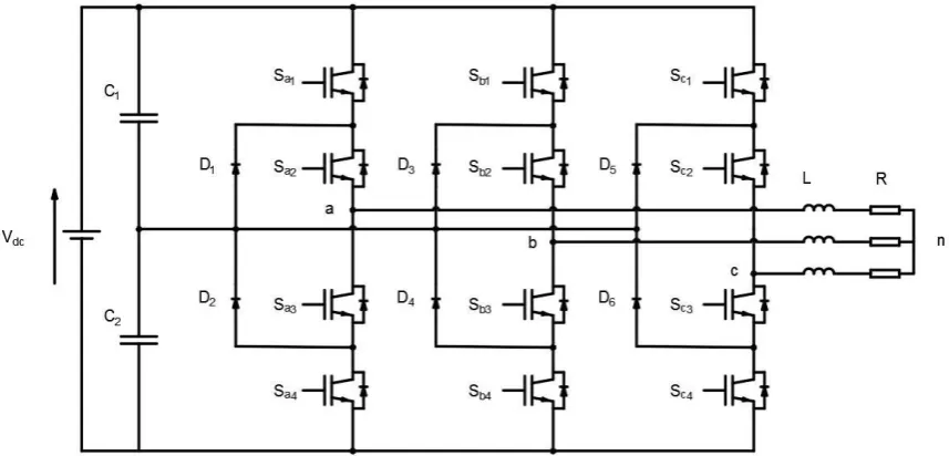
The model of the three-level, three-phase VSI with a resistive-inductive load is shown in Figure 1 [18, 19]. Here possible to find that there are four switches in each leg. Each phase will have three different output voltages by the control of any two switches. In order to simply show the status of each phase, the paper uses
S
a,S
b andS
cto represent the switch signals of the three phases, and they are defined as follows:1 2
2 3
3 4
1( ) :
on and
on
Switch Signal
= 0( ) :
on and
on
1( ) :
on and
on
a a
a a a
a a
p
S
S
S
o
S
S
n
S
S
1 2
2 3
3 4
1( ) : on and on
Switch Signal = 0( ) : on and on
1( ) : on and on
b b
b b b
b b
p S S
S o S S
n S S
1 2
2 3
3 4
1( ) : on and on
Switch Signal = 0( ) : on and on
1( ) : on and on
c c
c c c
c c
p S S
S o S S
n S S
[image:2.595.85.514.298.504.2]There will be 27 kinds of voltage vectors generated by combining the switch signal of each phase.
Fig 1: The model of three-level, three-phase VSI with resistive-inductive load
2.2
Discrete-time model
The differential equation of the three-level, three-phase VSI is:
a an a
b bn b
c cn c
di V R i L
dt di V R i L
dt di V R i L
dt
(1)
where
R
represents the load resistance, andL
represents the inductance,V
an,V
bn andV
cn represent the phase voltage ofeach phase,
i
a,i
b, andi
c represent the current of each phase. In order to further reduce the computation burden; transformthe voltage vectors of the three phases into an
frame by Clarke transformation.2
( 0.5 0.5 )
3 2
(0.5 3 0.5 3 ) 3
an bn cn
bn cn
V V V V
V V V
(2)
Now, utilize the forward Euler approximation of the derivate
of Equations (1) and (2) with the sampling period
T
s to design the discrete-time model of the three-level, three-phase VSI with a resistive-inductive load. Therefore, the mathematical model in the
frame is given by:
1 0 0
( 1) ( ) ( )
( 1) ( ) ( )
0 1 0
s s
i i i
i i s i
s
R T
T
i k L i k L V k
i k R i k T V k
T
L L
(3)
3.
MATHEMATICAL BACKGROUND
3.1
Laguerre Functions
[image:3.595.314.545.115.273.2]The z-transformation of the Laguerre networks is written as [1, 13, 20]:
1 1 1 ( ) ( ) 1 k k z z z z (4)
where
is the pole of the equations.The state space form of the
l
N( )
k
which is the inversez-transform of
N( , )
z
is:L k( )[ ( ) ( ) ( ) l k l k l k1 2 3 L ( )]lN k T (5)
The relationship between different instances can be achieved from Equation (4):
1
( 1) ( )
L k A L k (6)
where
2 2 3 3
0 0
0 0
( 1) ( 1)
l
N N N N
A L L M L (7) 2 ,
1 0 1
and L(0) is:
2 1 1
(0)T [1 - (-1)N N ]
L L (8)
In addition, Laguerre functions also have the orthonormal property,
0
0
( ) ( )
0, i
j
( ) ( ) 1, i
j
i j k
i j k
l k l k
l k l k
(9)3.2
Modified MPC
The Laguerre functions can approximate the difference of the reference voltage with fewer parameters:
*
1
( ) ( ) ( ) ( )
N
T
i j i j
j
V k k c k l k L k
(10)where is defined as:
1 1 1 ( ( ) ( ) ) ( ( ) ) ( ) p p N N T k L i k k
k Q k R k QA I k
(11)
with
T
QC C (12)
RLr Iw N N (rw0) (13)
1 1 0
( ) ( )
k
T k i T
i
k A BL i
(14)P
N
is the predictive horizon.A
andB
are the coefficients of the augmented state space function. The augmented state space function is:*
( 1) o ( )
( )
( 1) ( )
T
m i m m m i m
i
m i m m m i m
i k A i k B
V k
i k A I i k B
(15)
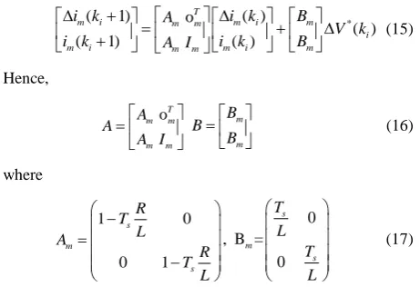
Hence, oT m m m m A A A I m m B B B
(16)
where 1 0 0 1 s m s R T L A R T L , 0 B = 0 s m s T L T L (17)
Finally, the required reference voltage at
k
ican be predicted at the basis of the difference of the required reference voltageand the actual load voltage at
k
i
1
.
1* *
( )i ( )+i i
-V k V k V k (18)
3.3
SVPWM of Three-level, Three-phase
VSI
After obtaining the required reference voltage, the next task is to get the switching sequence.
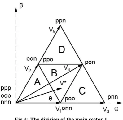
Fig 4: The division of the main sector 1
Figure 2 shows the voltage vectors of the level, three-phase VSI in
frame [22]. In Figure 2, the whole complex plane has been divided into six main sectors, and each main sector will be divided into four triangle sectors. In Figure 3, main sector 1 is considered as the example, and it is divided into A, B, C, and D triangle sectors. In the triangle sectors A, V1, V2, and zero-space vector are three basic voltage vectors; in the triangle sector B, V1, V2, and V4 are three basic voltage vectors; in the triangle sector C, V1, V3, and V4 are three basic voltage vectors; in the triangle sector D, V2, V4, and V5 are three basic voltage vectors.In order to choose the most proper switches, the first task is to determine the main sector by the angle of the required reference voltage vector. The second task is to determine the triangle sector by the angle and amplitudes in the frame of the required reference voltage vector. Finally, the basic voltage vector and the working switches will be chosen according to the symmetric seven-segment technique, and the corresponding working time will be computed as well.
The following rule will decide in which triangle sector the required reference voltage vector will be:
I
f *3 sin 3cos dc V V
uur
and 0 3
;
Then the required reference voltage vector is in the triangle sector A.
If the required reference voltage vector does not satisfy the requirement of the triangle sector A, and then:
If *
3 sin 3cos dc V V
uur
and 0 6
; or * 3
6sin dc V V
uur
and
6 3
;
then the required reference voltage vector is in the triangle sector B.
If the required reference voltage vector does not satisfy the requirements of triangle sectors A and B, and then:
If
* 2
3 sin 3cos dc V V
uur
and 0 6
;
then the required reference voltage vector is in triangle sector C.
If the required reference voltage vector does not satisfy the requirements of triangle sectors A, B, and D
If
* 2
3 sin 3cos dc V V
uur
and
6 3
;
then the required reference voltage vector is in triangle sector D.
After determining the working triangle sector, the next task is to control the switches according to the symmetric seven-segment technique and the corresponding working time.
The seven-segment technique will generate less THD than the three-segment technique and five-segment technique. According to the rule of the seven-segment technique, positive short-vectors are often used as the initial vectors, and only one status of switches can be changed every time. Table 1 shows the conventional seven-segment switching sequences of different triangle sectors in triangle sector 1.
The final task is to compute the time duration of each voltage vector. In triangle sector A of the main sector 1,T0,T1, and
2
T are:
* 1
2 3 | |
sin( )
3 dc
T V T
V
(19)
* 2
2 3 | |
sin dc T V T
V
(20)
0 1 2
T T T T (21)
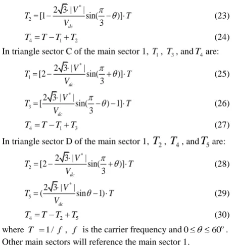
In triangle sector B of the main sector 1,T1, T2, andT4are:
* 1
2 3 | |
(1 sin )
dc V
T T
V
[image:4.595.68.267.76.269.2] (22)
Table 1. Conventional 7-segment switching sequences of different triangle sectors
Mode Switching sequences
A 1
V
poo
ooo
oon
onn
oon
ooo
poo
2
V
ppo
poo
ooo
oon
ooo
poo
ppo
B 1
V
poo
pon
oon
onn
oon
pon
poo
2
V
ppo
poo
pon
oon
pon
poo
ppo
C
poo
pon
pnn
onn
pnn
pon
poo
[image:4.595.78.523.624.746.2]* 2
2 3 | |
[1 sin( )]
3 dc
V
T T
V
(23)
4 1 2
T T T T (24)
In triangle sector C of the main sector 1, T1, T3, andT4are: *
1
2 3 | |
[2 sin( )]
3 dc
V
T T
V
(25)
* 3
2 3 | |
[ sin( ) 1]
3 dc
V
T T
V
(26)
4 1 3
T T T T (27)
In triangle sector D of the main sector 1,
T
2,T
4, andT
5are:* 2
2 3 | |
[2 sin( )]
3 dc
V
T T
V
(28)
* 5
2 3 | |
( sin 1)
dc V
T T
V
(29)
4 2 5
T T T T (30)
where T 1 / f , f is the carrier frequency and 0 60o . Other main sectors will reference the main sector 1.
[image:5.595.52.284.71.314.2]4.
SIMULATION
Table 2 lists the parameters that will be used for the simulation [21].
Table 2. Parameters of VSI
Parameter Value
Load Resistance(
R
) 5Load Inductance(
L
) 11mHDC Link Voltage(
V
dc) 100VReference Current Amplitude 8A
Reference Current frequency 50Hz
Sampling Time (
T
s) 25s4.1
Parameters Selecting
In this paper, selecting the proper scaling factor , the number of terms N , and the prediction horizon Np will significantly affect the control precision and response time of the three-level, three-phase VSI. In addition, more proper and shorterNp will not only ensure the control precision of the three-level, three-phase VSI but improve the efficiency of the whole system. After comparing with other parameters, when
is 0.2 and Nis 43, even ifNpequals 1, the maximum error and the mean error of one phase (phase
) are both very small. The value of the maximum error is 0.131A and the value of the mean error is equal to 0.055A in the steady state.4.2
Steady State Performance
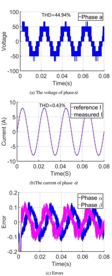
This paper applies the modified controller to the two-level, three-phase VSI and the three-level, three-phase VSI, respectively, and makes the comparison between them. As seen is Figures 4 and 5, the modified controller ensures the low THD of current and low errors of two kinds of VSIs in the steady state. However, the comparison also shows that the
steady-state performance of the three-level three-phase VSI is better than that of the two-level three-phase VSI with the modified controller. The THD of the voltage of the two-level, three-phase VSI is 79.78%, which is almost twice the THD of the voltage of the three-level, three-phase VSI (44.94%).
Furthermore, the THD of the current of the three-level, three-phase VSI, which is 0.43% is just half of the THD of the current of the three-level, three-phase VSI, which is 0.86%. With regard to the errors of phase
and phase
, it is obvious that the maximum value of errors of the two-level, three-phase VSI are higher than that of the three-level VSI.(a)The voltage of phase
.(b) The current of phase
[image:5.595.331.525.204.678.2](c) Errors
[image:5.595.61.274.377.515.2](a) The voltage of phase
(b)The current of phase
[image:6.595.62.277.56.586.2](c) Errors
Fig 5: Steady state performance of the level three-phase VSI with the modified controller
(a) The reference phase is changed by +60° at 0.025s
[image:6.595.337.522.74.210.2](b) Error of phase
Fig 6: Two-level, three-phase VSI with the modified controller
(a) The reference phase is changed by +60° at 0.025s
[image:6.595.343.512.587.738.2](b) Error of phase
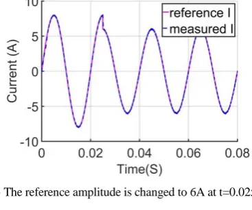
(a) The reference amplitude is changed to 6A at t=0.025s.
[image:7.595.64.267.72.728.2](b) Error of phase
Fig 8: Two-level, three-phase VSI with the modified controller
(a) The reference amplitude is changed to 6A at t=0.025s.
(b) Error of phase
Fig 9: Three-level, three-phase VSI with the modified controller
4.3
Robust Test
Figures 6 and 7 show the situations of the two-level and three-level, three-phase VSI controlled by the modified controller when the reference phase is changed by +60° at t=0.025s. Eight key data have been labelled in Figures 6(b) and 7(b) in order to clearly show the effects. The maximum error of the two-level, three-phase VSI is 4.039A, and it will return to normal after 0.02745s. In terms of the three-level, three-phase VSI, its maximum error is 3.966A, and after 0.02743s it can track the reference current well. Furthermore, its error is half that of the two-level three-phase VSI at that point. These data indicate that when the level, three-phase VSI is controlled by the modified controller, it can achieve fewer errors and faster response than the two-level, three-phase VSI.
The next task is to check the robustness when the reference amplitude is changed from 8A to 6A at 0.025s. Figures 8(b) and 9(b) make it clear that the maximum error of the three-level three-phase VSI is lower than that of the two-three-level, three-phase VSI. In addition, the mean error of the two-level, phase VSI is 0.057A, but the mean error of the three-level, three-phase VSI is just 0.038A.
5.
CONCLUSION
This paper proposes the application of the combination of the modified MPC and SVPWM to the control of the three-level, three-phase VSI with a resistive-inductive load. Laguerre functions will be used to modify MPC, and the voltage vectors will be transformed into an frame in order to reduce the computation burden. In addition, the parameters of the modified controller will be computed in advance. A high THD is very harmful to the equipment, so symmetric seven-segment technique is chosen to ensure the low THD of the output current.
In order to demonstrate the superiority when the modified controller is applied to the three-level, three-phase VSI with the resistive-inductive load, this paper tests the steady-state performance and its robustness. Simultaneously, the two-level, three-phase VSI with the modified controller is made as the comparison. As seen from the extensive simulations, when the three-level, three-phase VSI is manipulated by the modified controller, it can generate fewer errors and a lower THD. Furthermore, its robustness can be improved.
6.
ACKNOWLEDGMENTS
This research was supported by the Brain Research Program through the National Research Foundation of Korea (NRF) funded by the ministry of science, ICT and Future Planning (NRF-2017M3C7A1044815).
7.
REFERENCES
[1] Abdissa, C.M., Chong, K.T. 2017. Stabilization and Voltage Regulation of the Buck DC-DC Converter Using Model Predictive of Laguerre Functions, Studies in Informatics and Control, 26(3),315-324.
[2] Karasani, R. R., Borghate, V. B., Meshram, P. M. et al. 2017. A three-phase hybrid cascaded modular multilevel inverter for renewable energy environment. IEEE Transactions on Power Electronics, 32(2), 1070-1087.
[image:7.595.75.259.77.230.2]three-phase inverters for renewable energy applications. International Journal of Control, 90(1), 53-67.
[4] Kumari, M., Thakura P. R. and Badodkar D. N. 2018. Transient analysis of three-phase high-power voltage source inverter with nonlinearities in hybrid electric vehicles, IEEE Transactions on Power Electronics, 33(4), 3672-3680.
[5] Sebastian, C. R. and Rajeevan, P. P. 2018. Load-commutated SCR-based current source inverter fed induction motor drive with open-end stator windings, IEEE Transactions on Industrial Electronics, 65(3), 2031-2038.
[6] Chen, K., Ji, S. m. and Zhang, L. 2016. Two-level three-phase voltage source inverter fed low-power AC induction motor based on unipolar pulse-width modulation method, IET Power Electronics, 9(3), 435-440.
[7] Ewanchuk, J. and Salmon, J. 2013.Three-limb coupled inductor operation for paralleled multi-level three-phase voltage sourced inverters, IEEE Transactions on Industrial Electronics, 60(5), 1979-1988.
[8] Holtz, J. 199. Pulsewidth modulation for electronic power conversion. In Proceedings of the IEEE, 82(8),1194-1214.
[9] Liu, Z., Zheng, Z., Sudhoff, S. D., Gu, C and Li, Y. 2016. Reduction of common-mode voltage in multiphase two-level inverters using SPWM with phase-shifted carriers. IEEE Transactions on Power Electronics, 31(9), 6631-6645.
[10]Hu, J. S., Lin, J. N. and Chen, H. C. 2017. A discontinuous space vector PWM algorithm in abc reference frame for multilevel three-phase cascaded H-Bridge voltage source inverters. IEEE Transactions on Industrial Electronics, 64(11), 8406-8414.
[11] Rodriguez, J. et al. 2007. Predictive Cur-rent Control of a Voltage Source Inverter, IEEE Transactions on Industrial Electron-ics, 54(1), 495-503.
[12]Vazquez, S., Rodriguez, J. and Rivera, M. et al. 2017. Model predictive control for power converters and drives: advances and trends. IEEE Transactions on Industrial Electronics, 64(2), 935-947.
[13]Chen, M., Zhang, A. and Chong, K. T. 2018. A novel controller design for three-phase voltage source inverter. International Journal of Control, Automation and Systems, 1-10.
[14]Wang, L. 2004. Discrete model predictive controller design using Laguerre functions, Journal of Process Control, 14(2), 131-142.
[15] Hoon, Y., MohdRadzi, M. A. and Hassan, M. K. et al. 2017. A refined self-tuning filter-based instantaneous power theory algorithm for indirect current controlled three-level inverter-based shunt active power filters under non-sinusoidal source voltage conditions, Energies, 10(3), 277.
[16]Jena, S., Panigrahi, C. K., Sahoo, S. et al. 2016. Current harmonics reduction of three phase grid connected pulse width modulated voltage source inverter by hysteresis current controller with offset band, 2016 7th India
International Conference on Power Electronics (IICPE), Patiala, pp. 1-6.
[17] Ojha, S., Sharma, C. and Pandey, A. K. 2017. Comparative analysis of close loop three level voltage source inverter using sinusoidal pulse width modulation and third harmonic injection method for different loads, 2017 Second International Conference on Electrical, Computer and Communication Technologies (ICECCT), Coimbatore, pp. 1-6.
[18] Xia, C., Shao, H., Zhang, Y. et al. 2013. Adjustable proportional hybrid SVPWM strategy for neutral-point-clamped three-level inverters, IEEE Transactions on Industrial Electronics, 60(10), 4234-4242.
[19] Masisi, L., Pillay P. and William-son, S. S. 2016. A modulation strategy for a three-level inverter synchronous reluctance motor (SynRM) drive, IEEE Transactions on Industry Applications, 52(2), 1874-1881.
[20] Wang, L. 2009. Model Predictive Control System Design and Implementation Using MATLAB®, Springer.
[21] Kharjule, S. 2015. Voltage source inverter, 2015 International Conference on Energy Systems and Applications, Pune, 537-542.
[22] Zhezhi, Y., Lingzhi, Y., Hanmei, P. et al. 2009. Study of simplified SVPWM algorithm based on three-level inverter, 2009 IEEE 6th International Power Electronics and Motion Control Conference, Wuhan, pp. 876-881.
8.
AUTHOR’S PROFILE
Ming Chen, received his Master’s degree in Electrical & Electronics Engineering from Chonbuk National University in 2018. His research interest is Predictive Control of Electrical drives and Power Converters.
Abdissa Chala Merga, received a PhD degree in Electronic Engineering from Chonbuk National University in 2018. His research interest is Predictive Control of Electrical drives and Power Converters.
Gil-Soo Km, received he Ph.D. degree from the Graduate School, Dongguk University. Currently, he is an Assistant Professor at the School of industry-university cooperation, Chonbuk National University, ROK.