MCRP 2-24B
Remote Sensor Operations
U.S. Marine Corps
13
Jul
2004
E R R A T U M
to
MCRP 2-24B
REMOTE SENSOR OPERATIONS
1. Change the publication short title to read “MCRP
2-24B” (vice MCWP 2-15.1) and change PCN to 144 000153 00
(vice 143 000016 00)
Headquarters United States Marine Corps
Washington, DC 20380-1775
17 April 1997
FOREWORD
Marine Corps Warfighting Publication (MCWP) 2-2.3,
Remote Sensor Operations,
is the first
in a new series of doctrinal publications on intelligence collection operations. MCWP 2-1,
Intelligence Operations
(under development) and FMFM 3-21,
MAGTF Intelligence
Opera-tions,
provide doctrine, tactics, techniques, and procedures for intelligence collection
opera-tions. MCWP 2-2.3 complements and expands upon this information by detailing doctrine,
tactics, techniques, and procedures for the conduct of remote sensor operations in support of
the Marine Air-Ground Task Force (MAGTF). The primary target audience of this publication
is intelligence personnel responsible for the planning and execution of sensor operations.
Per-sonnel who provide support to remote sensor operations or who utilize the reporting from
these operations should also read this publication.
MCWP 2-2.3 describes aspects of remote sensor operations including doctrinal fundamentals,
equipment, command and control, planning, execution, logistics, and training. MCWP 2-2.3
provides the information needed by Marines to understand, plan, and execute remote sensor
operations in support of the MAGTF.
Reviewed and approved this date.
BY DIRECTION OF THE COMMANDANT OF THE MARINE CORPS
PAUL K. VAN RIPER
Lieutenant General, U.S. Marine Corps
Commanding General
Marine Corps Combat Development
Command
To Our Readers
Changes: Readers of this publication are encouraged
to submit suggestions and changes that will improve it. Recommendations may be sent directly to
Commanding General, Doctrine Division (C42), Marine Corps Combat Development Command, 3300 Russell Road, Suite 318A, Quantico, VA 22134-5021 or by fax to (703) 784-2917 (DSN 278-2917) or e-mail to smb@doctrine div@mccdc.
Recommendations should include the following information:
Location of change
Publication number and title Current page number
Paragraph number (if applicable) Line number
Figure or table number (if applicable) Nature of change
Add, delete
Proposed new text, preferably double-spaced and typewritten
Justification and/or source of information
Additional copies: A printed copy of this publication
may be obtained from Marine Corps Logistics Base, Albany, GA 31704-5001, by following the
instructions in MCBul 5600, Marine Corps Doctrinal
Publications Status. An electronic copy may be
obtained from the Doctrine Division, MCCDC, World Wide Web homepage, which is found at the following uniform resource locator:
pronouns used in this publication refer to both
men and women.
Record of Changes
Log completed change action as indicated.
Change Number
Date of Change
Date Entered
Remote Sensor Operations
Table of Contents
Page
Chapter 1.
Remote Sensor Operations Fundamentals
1001. Remote Sensor Systems 1-1
1002. Evolution of Remote Sensors 1-1
1003. Remote Sensor Employment Principles 1-4
1004. Concept of Employment 1-5
Chapter 2.
Tactical Remote Sensor System
2001. Tactical Remote Sensor System Equipment Suite 2-1
2002. Sensors 2-1
2003. Relays 2-3
2004. Monitoring Equipment 2-4
2005. Future Capabilities 2-6
Chapter 3.
Command and Control of Remote Sensor Operations
3001. Remote Sensor Command and Control 3-1
3002. Sensor Control and Management Platoon 3-2
3003. Tasking Remote Sensor Assets 3-4
3004. Remote Sensor Control Agencies 3-5
3005. Communications for Remote Sensor Operations 3-5
Chapter 4.
Planning for Remote Sensor Operations
4001. Remote Sensor Support to Operations 4-1
4002. Planning Considerations 4-2
4003. The Sensor Employment PlanningCycle 4-3
4004. Sensor Surveillance Plan 4-5
Chapter 5.
Execution of Remote Sensor Operations
5001. Employment Considerations 5-1
5002. Emplacement Operations 5-2
5003. Monitoring Operations 5-3
5004. Disseminating Sensor Information 5-7
5005. Utilizing Sensor Information 5-9
Chapter 6.
Combat Service Support
6001. Maintenance 6-1
6002. Supply 6-1
6003. Transportation 6-1
Chapter 7.
Training
7001. Types of Training 7-1
7002. Tactical Remote Sensor System Orientation and Familiarization 7-1
7003. Tactical Remote Sensor System Planning and Employment Training 7-1
7004. Operator Training 7-1
7005. Maintenance Training 7-1
7006. Sensor Emplacement Training 7-2
7007. MAGTF Training 7-2
Appendices
A Miniature Intrusion Detection System A-1
B Tactical Remote Sensor System Technical Characteristics B-1 C Remote Sensor Planning Orientation Briefing Format C-1
D Checklist for Determining the Suitability of Remote Sensor Employment D-1
E Sensor Surveillance Plan Decision Brief Format E-1
F Sensor Surveillance Plan Format F-1
G Sketch Diagrams and Sensor Emplacement Tags G-1
H Remote Sensor Reports H-1
I Equipment Density List for a Sensor Employment Team and
Sensor Employment Squad I-1
J Glossary J-1
1001. Remote Sensor Systems
A remote sensor system is a continuous, all-weather surveil-lance system which provides monitoring of activity in elected areas. The system consists of sensors, relays, and monitoring equipment; system components are emplaced at selected points on the battlefield to provide an integrated sensor net-work. Sensors are placed adjacent to the desired surveillance area, normally a route or point target (objective, helicopter landing zone, or assembly area). Individual sensors are acti-vated by seismic, magnetic, infrared, or optical detections of moving targets.
Detections are transmitted by FM radio link directly or via re-lays to the monitoring equipment. Operators at the monitoring site interpret the detections to determine location, direction, and speed of movement of the detected targets. They may also be able to provide an estimated number of vehicles or personnel detected and a generalized identification of the type of targets detected (e.g., tracked vehicles, wheeled vehicles, or personnel), depending upon the type of sensors employed and the nature of the target’s activity. This information is for-warded to intelligence, operations, and fire support agencies in the form of sensor reports.
1002. Evolution of Remote Sensors
Remote sensors entered the Marine Corps inventory in 1967 during the Vietnam conflict. The development of a sophisti-cated remote sensor system permitted the continu- us surveil-lance of vast areas, providing indications and warning of future enemy activities. Remote sensors decreased the num-ber of personnel required to monitor the movements of men and material and reduced the risk associated with surveillance operations by providing the capability to monitor targets without physically locating personnel in the surveillance area. The intelligence developed from information provided by the remote sensor system was used to plan and execute numerous successful operations by Marine forces.
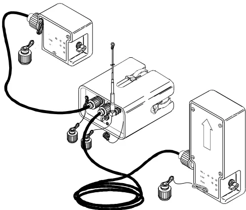
The use of sensors in Vietnam established their value as an intelligence collection asset. The third-generation Tactical Re-mote Sensor System (TRSS-Phase III or TRSS III) has been a mainstay of Marine Corps intelligence collection capability since 1972. In 1992, a new generation of sensor equipment, TRSS-Phase V (TRSS V), entered the inventory. TRSS V provides a greatly enhanced remote sensor capability through the use of light-weight sensors, new detection technology, and improved information processing capabilities. See figure 1-1 for the TRSS and its components.
1003. Remote Sensor Employment
Principles
Chapter 1
Remote Sensor Operations Fundamentals
Figure 1-1. Remote Sensor Terminology.
Sensor String. A grouping of 2 or more (usually 3-5) remote sen-sors emplaced within the same area to provide coverage of a spe-cific surveillance target such as a road intersection, choke point, or objective. Sensors are normally employed in strings, since a string can provide significantly more information than an individual sen-sor. Target speed, classification, and direction of movement can be determined by tracking the target as it activates each of the Remote Sensor. Device that detects the physical presence of anob-ject by means of energy reflected or emitted by the obob-ject and trans-mits information from the detection to a specially equipped monitoring site located beyond visual observation range of the sen-sor. Also referred to as unattended ground sensor (UGS).
MCWP 2-2.3 Remote Sensor Operations
1-3
Figure 1-1. Remote Sensor Terminology (Continued).
Sensor Network or Net. An integrated network system ofsen-sor strings, relays, and monitoring sites established to provide sensor surveillance over all or part of the area of operations. Sensor Field. A grouping of sensor strings within the same
geo-graphic area which provide surveillance over a specific portion of the battlefield or a group of related surveillance targets, e.g. a series of sensor strings covering the approaches to and exits from a river
Remote sensors can be employed in almost any tactical situa-tion. Optimal employment is in areas where major movement is restricted to a few key lines of communications and the traffic pattern of military and civilian activity can be easily discriminated. Remote sensor operations are ideally suited to support relatively stable situations such as long-term defen-sive or security operations ashore, where the time and re-sources are available to develop an extensive sensor network throughout the area of operations. Remote sensors have lim-ited utility in fast-moving mobile operations, raids, and other limited duration operations unless adequate time and means are provided to emplace sensors to support the planned operation. In addition, the employment of sensors in areas of open terrain or heavily congested urban concentration re-quires detailed planning to ensure the sensor network can pro-vide the desired information in those environments.
a. Remote Sensor Applications
(1) General Surveillance. Sensors are used to provide general surveillance of lines of communications, beachheads, helicopter landing zones, assembly areas, objectives, and other named areas of interest (NAIs). Sensor information is used to develop the general enemy situation and support the scheme of maneuver through the detection of enemy activity near insertion points or other objectives.
(2) Early Warning. Sensors are placed along avenues of approach to provide early warning of enemy movement to-ward friendly positions. Sensor strings may be placed for-ward, on the flanks, or in the rear of friendly units to facilitate force protection. In this application, sensors should be im-planted as far forward of friendly positions as possible, ex-ploiting the extended range of the remote sensor system to provide maximum reaction time.
(3) Target Acquisition.A well-developed sensor network can be used for target acquisition. Sensors are implanted along key enemy lines of communications or NAIs and sen-sor activations are used to initiate targeting action. The key limitation of sensors in this application is the inability to dis-criminate between hostile, friendly, and noncombatant activ-ity. As a result, sensor data must normally be confirmed by some other surveillance asset. Sensors do provide an excellent means of facilitating the targeting process through the cueing of other target acquisition sources, and, once a target is posi-tively identified, a well-planned sensor network can track a target as it moves across the battlefield. If used for target ac-quisition, care must be taken not to compromise the location
of sensor strings through repeated attacks on enemy forces lo-cated in the same area.
b. Capabilities of Remote Sensors
(1) Remote Surveillance. Remote sensors provide an extended-range surveillance capability without the require-ment to maintain a physical presence in the surveillance area. Through the use of relays to maintain line-of-sight communi-cations connectivity between the sensors and the monitoring site, monitoring operations can be conducted a hundred miles or more from the surveillance area. This capability gives the MAGTF commander a means to economically monitor ac-tivity in the area of operations or area of interest, conserving the use of other reconnaissance and surveillance assets for other critical tasks.
(2) Target Detection and Classification. Sensors can confirm or deny the presence of activity in the designated area and give a general indication of the type and volume of ac-tivity. Sensors can provide the number, general type, location, direction, and speed of most acquired targets. The degree of detail and accuracy of the target classification is a function of the number and type of sensors used as well as the profi-ciency of the monitoring site operator. While sensor data alone is rarely sufficient for target acquisition, sensors can be used to cue other surveillance and target acquisition assets to obtain the data required for targeting.
(3) Near Real-time Reporting. Electronic transmission of sensor detections to the monitoring site provides near real-time reporting of activity in the surveillance area. Automated processing equipment can generate a sensor report for trans-mission within minutes of an activation.
(4) Continuous Operations. Sensors operate day and night, in all weather conditions. Individual sensors can oper-ate continuously for up to 30 days; relay systems can function for up to 45 days. Battery life is the primary factor limiting sensor/relay endurance; battery life is de-pendent upon the number of activations and transmissions required along with weather and other environmental factors.
(6) Flexibility.Remote sensors can be employed in a variety of means to support the concept of operations. Sensors can be hand emplaced by mobile and/or foot patrols or dropped from aircraft. Detections can be relayed and processed in real time or stored by relays for transmission on command.
c. Limitations of Remote Sensors
(1) Implant Operations. The time and resources required to implant sensors and relays are the key limitations on re-mote sensor operations. The placement of sensors and relays must be planned in detail and accomplished well in advan ce of when the information is needed. The tactical situation may preclude use of aircraft for implant operations and limit the number of ground patrols which can be employed for im -planting sensors.
(2) Terrain Masking. Remote sensors require radio fre-quency line-of-sight between sensors and the monitoring site; as a result, they are susceptible to terrain masking. Effective employment requires detailed planning of sensor, relay, and monitoring site locations as well as knowledge of the capabili-ties and limitations of the transmitters. Terrain masking may preclude extended range employment of sensors in mountain-ous areas.
(3) Limited Target Discrimination. Remote sensors by themselves cannot provide positive target identification. Sen-sors activate in response to some type of physical presence. Using a mix of sensor types can provide a general category of the target, e.g., personnel, wheeled vehicles, or tracked vehi-cles, but sensors will not be able to determine whether the target is friendly, enemy, or non-combatant. Sensor activa-tions must be combined with other information to provide a positive target ident- ification.
(4) Responsiveness.Because of the time required to plan and execute implant operations, remote sensors are generally not responsive to rapidly changing requirements. Advance planning of sensor support through detailed study of the mis-sion, enemy, area of operations, and commander’s intent pro-vides the best means of anticipating future sensor requirements.
(5) Sensor Positioning. Accurate emplacement of the sensors is crucial to obtaining coverage of the desired area. Knowing the exact location of the implanted sensor is critical to successful relay and monitoring operations. As a result, implants must be done according to a plan and the location of
the implants must be accurately reported to the monitoring agency.
(6) Inventory. Sensor assets are limited. Each Marine expe-ditionary force (MEF) will have sufficient sensors for em-placing approximately 200 sensor strings of 3-4 sensors each. Furthermore, while expendable, sensors are expensive and only a small war reserve stock is planned.
(7) Failure Rate. Inherent in all electronic systems is the possibility of component failure. Loss of any single electronic component may render the device inoperable and degrade the operation of the overall system.
1004. Concept of Employment
Sensors are implanted in strings of 2-5 sensors per string. Whenever possible, a variety of sensors will be used within a string in order to provide maximum target discrimination data. Strings are implanted according to a coherent sensor surveillance plan, facilitating comprehensive coverage of des-ignated surveillance sites and the general area of operations. Sensor strings are integrated with data relays and monitoring sites, forming a sensor network. See figure 1-2.
a. Command and Control
(1) Control. Marine Corps remote sensor assets are main-tained under centralized control of the Sensor Control and Management Platoons (SCAMP). SCAMP or SCAMP de-tachments maintain remote sensors and associated equipment, plan remote sensor employment, perform air-implant tions from rotary wing aircraft, assist in hand-implant opera-tions, and monitor and report information generated by sensor activations. Operational control of remote sensor operations is exercised by the MAGTF Command Element (CE) through the Surveillance and Reconnaissance Center (SARC). The CE directs the employment of the SCAMP through the sup-port relationships detailed below.
(2) Support Relationships
(a) General Support. Due to the depth and range of sen-sor operations and the need to integrate sensen-sor information with other deep surveillance assets, SCAMP normally oper-ates in General Support (GS) of the MAGTF. In GS, the MAGTF commander, through his G-2/S-2, determines prior-ity of support, locations of sensor strings and monitoring sites, and information dissemination flow.
(b) Direct Support. The entire platoon or portions of it may be placed in Direct Support (DS) of a designated unit. Under DS, priority of support goes to the supported unit. A SCAMP liaison element is provided to the supported unit. A monitoring site is collocated with the command post of the supported unit, or the unit receives sensor information directly from a designated monitoring site.
b. Planning
Sensor operations are planned to satisfy the intelligence col-lection requirements of the supported command. The Intelli-gence Preparation of the Battlespace (IPB) process
provides the key elements to support remote sensor operations planning, including: identification of entry points, lines of communications, threat avenues of approach, designation of NAIs, and evaluation of communications line-of-sight condi-tions in the area of operacondi-tions. IPB data is analyzed to deter-mine the optimal locations of sensor strings, relays, and monitoring sites. Requirements for implant operations are de-veloped along with concepts for the monitoring and dissemi-nation of sensor data. These elements are combined into a sensor surveillance plan.
c. Implant Operations
There are two types of implant operations—hand-implant and air-implant. Implant operations are tasked, coordinated, and controlled by the SARC. Implant operations are planned jointly by the SCAMP and the designated implant unit.
(1) Hand-Implant Operations. Hand-implant operations
offer the following advantages over air-implants: Greater accuracy of sensor placement.
Ability to employ full sensor suite (air-drop-pable sensors are limited to seismic detectors). Flexibility to adapt implant plan to conditions in the surveillance area.
[image:14.612.57.533.97.362.2]implanting sensors, and they brief units tasked with implant missions. The SCAMPs are not manned, trained, or equipped to operate in the deep or distant reconnaissance areas and should not be tasked to undertake implant missions in these areas. However, a remote sensor operator should accompany any patrol tasked with a sensor implant mission, to ensure the correct emplacement and functioning of the sensors. Due to the importance of proper siting and testing of relays, a remote sensor operator will always be included in any patrol assigned to emplace a ground relay. SCAMP personnel can carry out emplacement missions when access to the implant area does not require unique reconnaissance skills or security measures beyond the platoon’s organic capabilities; due to the limited number of remote sensor operators, the use of SCAMP per-sonnel to carry out sensor emplacement may detract from on-going sensor planning and monitoring activity.
(2) Air-Implant Operations. The speed and range of air-craft provide a means to rapidly emplace a large number of sensors across a wide area. Due to current equipment con-figuration, only rotary wing aircraft can drop sensors, limiting air-implant operations to areas where the air defense threat is relatively low. Additional disadvan-tages of air dropping are decreased accuracy and limited types of sensors available. The SARC will request and coordinate air support for air-implant missions. SCAMP
per-sonnel will coordinate with the designated squadron on the de-tails of the mission and perform the actual air drops of the sensors.
d. Monitoring Operations
(1) Processing Sensor Data. The SCAMP performs monitoring operations in accordance with the Sensor Surveil-lance Plan. Sensor activations are received by TRSS monitoring equipment. The monitoring equipment provides real-time, on-screen monitoring of sensor activations, data storage, and automated assistance in the analysis of sensor data generation of sensor reports.
(2) Monitoring Sites. A monitoring site consists of sensor monitoring equipment, communications equipment, and one or more sensor operators. Primary monitoring equipment is mounted in a HMMWV; a man-portable workstation can be remoted from each primary monitoring site. Monitoring sites are located to maintain communications line-of-sight with sensors and/or relays. Every effort is made to locate
monitor-ing sites in proximity to supported unit command posts to facilitate rapid reporting of sensor-derived information.
(3) Redundancy. The monitoring plan attempts to estab-lish redundancy in the sensor network, insuring that at least two separate sites can receive activations from each sensor or relay. Redundancy permits displacement of monitoring sites by echelon, ensuring continuous monitoring of the sensor net-work, and reduces the impact of the loss of any single site due to equipment failure or enemy action.
e. Dissemination of Sensor Information
Sensderived information will be disseminated in acc or-dance with the intelligence dissemination plan. Sensor reports may be disseminated via area networks, a sensor reporting ra-dio net, or other reconnaissance rara-dio net. In GS, these re-ports go the SARC for further dissemination throughout the force. In DS, reports go directly to the supported unit as des-ignated by that unit’s G-2/S-2. However, any unit may enter the sensor reporting net to receive sensor reports from the monitoring sites in near-real time.
(reverse blank)
2001. Tactical Remote Sensor System
Equipment Suite
A TRSS is made up of— Sensors
Communications data-relay devices Monitoring equipment
[image:16.612.328.557.438.678.2]One complete TRSS suite consists of the equipment listed in figure 2-1. A suite has sufficient equipment to implant and monitor 24 hand-emplaced sensor strings and 8 air-delivered strings. It is intended to support a Marine expeditionary unit (MEU). Each SCAMP operates six TRSS suites.
Detailed descriptions of TRSS components are provided in appendix B.
2002. Sensors
A sensor consists of a detection device, an encoder transmitter unit (ETU), an antenna, cabling, and associated connectors. Sensors detect changes in the physical environment through a variety of means. When activated by a target, the sensor sends an electronic impulse to the ETU. The impulse is en-coded and transmitted to a relay or monitoring site via VHF radio signal.
Detection devices are placed within detection range of the tar-get area, either on or in the round, depending on the type of detector. For hand-emplaced sensors, the detector is attached
to the ETU by means of a cable and the encoder transmitter is buried in the ground or concealed in vegetation with its an-tenna extended. Air-delivered sensors are self-contained units, consisting of a seismic detector, encoder transmitter, and antenna in one package designed to bury itself in the ground when dropped from an aircraft. This package is des-ignated the air-delivered seismic intrusion detector (ADSID). See figure 2- 2.
Tactical Remote Sensor System
A remote sensor system consists of sensors, communications data-relay devices, and moni-toring equipment. The current Marine Corps remote sensor system is designated the Tacti-cal Remote Sensor System (TRSS). TRSS provides the capability to establish an integrated sensor network in support of the MAGTF intelligence collection plan. TRSS equipment in-cludes a variety of hand-emplaced and air-deliverable sensors, ground relays, and portable and mobile monitoring devices.
Seismic Intrusion Detectors (SID)
24
Infrared Intrusion Detectors (IRID)
24
Encoder Transmitter Units (ETU)
24
Encoder Transmitter Unit/Seismic Intrusion Detectors (ETU/SID)
96
Air-Delivered Seismic Intrusion Detectors (ADSID)
24
Ground Relays 5
Portable Monitors 4
Sensor Mobile Monitoring Systems
1
a. Detector Types
(1) Seismic.The seismic intrusion detector (SID) is the ba-sic detector. The SID is equipped with a seismic geophone which detects ground vibrations caused when personnel or vehicles pass within the geophone’s detection range. SIDs have an average detection radius of 25 meters for personnel and 100 meters for vehicles. The detection radius will vary with soil type; the sensor’s sensitivity may be adjusted to suit specific environmental conditions. See figure 2-3.(2) Magnetic. Magnetic sensors are confirming sensors, primarily used to detect the presence of vehicles or distinguish between vehicles and personnel. They detect disturbances in a self-generated magnetic field caused by the presence of fer-rous metals. They can also determine direction of movement across their magnetic field, i.e., left-to-right or right-to-left. Magnetic detectors have a limited radius: 3 meters for per-sonnel and 25 meters for vehicles. Magnetic sensors cannot be implanted from the air. See figure 2-4.
[image:17.612.51.285.131.275.2]2-2
MCWP 2-2.3 Remote Sensor Operations
Figure 2-3. Hand-emplaced Seismic
Intrusion Detector with
[image:17.612.47.559.280.714.2]Encoder Transmitter Unit.
Figure 2-2. Air-delivered Seismic
Intrusion Detector.
Figure 2-4. Magnetic Intrusion
Detector with
[image:17.612.316.547.419.693.2](3) Infrared. Infrared sensors are another type of confirm-ing sensor; they are particularly useful for countconfirm-ing the number of objects (personnel or vehicles) moving through a sensor string. Infrared sensors use a passive infrared detector to sense changes in ambient temperature caused by the move-ment of an object through its field of view. Infrared detectors can also determine direction of movement across their field of vision. Infrared detectors have a unidirectional detection range of 15 meters for personnel and 100 meters for vehicles. Infra-red detectors must be above ground with their sensor head sited to provide an unobstructed field of view to the surveil-lance area. They cannot be implanted from the air. See figure 2-5.
b. Encoder Transmitter Units.
ETUs contain the logic, circuitry, and power source necessary for the transmis-sion of sensor detections. A common ETU is used with all three types of hand-emplaced detectors; two detectors can be attached to each ETU. See figure 2-6.In addition, there is an ETU/SID which consists of a seismic detector and ETU integrated into a single package. See figure 2-7. For air-delivered sensors, an ETU is integrated into the ADSID package. ETUs transmit using one of 599 available VHF radio channels; the channel is selected prior to im-plant and cannot be changed without recovering the ETU. In addition to detections, ETUs transmit periodic messages to confirm proper operating status and a specially
coded message to indicate that a sensor has been tampered with. ETUs are powered by standard C-cell batteries. Battery power is sufficient for 30 days of continuous operations; since the battery is used primarily to transmit sensor activa-tions, battery life may be extended significantly if sensor de-tections are limited.
2003. Relays
[image:18.612.57.297.472.706.2]Relays provide line-of-sight communications connectivity be-tween sensors and monitoring sites, extending the range of the TRSS and permitting its use in restricted terrain. Relays con-sist of a receiver/transmitter, control circuitry, power source, and antenna. See figure 2-8. The relay can be programmed to relay incoming data in real time or store the data until re-motely commanded to transmit the data to an available monitoring site. Relay is accomplished via VHF or UHF ra-dio link; UHF is used for the transmission of stored data at a faster data rate. Relay functions such as channel selection and operating mode can be controlled remotely via VHF link from the monitoring site. Relays are hand-emplaced; the relay and power source are concealed on or under the ground with only the antenna extending from the camouflaged relay equipment. A single battery pack provides 30 days of con-tinuous operation; additional battery boxes can be connected to provide extended operational periods.
[image:18.612.325.568.478.685.2]Figure 2-5. Infrared Intrusion Detector
with Encoder Transmitter Unit
.
Figure 2-6. Encoder Transmitter Unit
with Seismic Intrusion Detector
and
2004. Monitoring Equipment
Monitoring equipment receives data from sensors and relays, processes the data to derive the maximum amount of infor-mation, and generates an automated sensor report. Sensor op-erators verify the reports and disseminate them to the appropriate agency. TRSS uses two types of monitoring equipment: the sensor mobile monitoring system and port-able monitors. Both can receive, decode, and display sensor data from the U.S. Army Improved Remotely Monitored Battlefield Sensor System (I-REMBASS) and the Miniature Intrusion Detection System (MIDS).
a. Sensor Mobile Monitoring System.
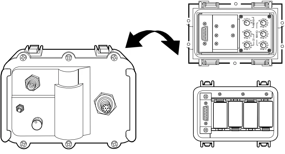
The sensor mobile monitoring system provides equipment for the receipt, storage, processing, display, and reporting of remotesensor activity. The sensor mobile monitoring system is a self-contained system of monitoring, processing, and communications equipment mounted on the back of a HMMWV. See figure 2-9. A system has two workstations, each of which can monitor up to 504 sensors. Either one of the monitoring workstations can be displaced from the shelter to provide limited, stand-alone monitoring capability at re-mote locations.
b. Portable Monitors.
A portable monitor is a hand-held receive/display unit that receives, decodes, and displays sensor identification code transmissions. See figure 2-10. It is primarily used to perform field operational checks at the sen-sor implant site. It can be used to monitor sensen-sor activations on a limited basis, but all data received by the portable moni-tor must be processed manually.2-4
MCWP 2-2.3 Remote Sensor Operations
[image:19.612.68.522.95.341.2]Figure 2-8. Ground Relay Assembly.
Figure 2-9. Sensor Mobile Monitoring System.
[image:20.612.145.546.399.713.2]2005. Future Capabilities
a. Day/Night Thermal Imager.
A day/night thermal imager is under development which will provide an enhanced confirmation/classification capability. The imager consists of an imaging head and an imager transmission unit. See figure 2-11. When activated, a sensor in the imaging head will take a thermal image of the target in its field of view. See figure 2-12. The image will be transmitted to a relay or monitoring site for analysis and integration with other sensor data. The imager head has a 28 degree field of vision and a range of 9 meters for a full screen image. The imager has an inter-nal SID which activates the imager head when it detects vi-brations from a target; it can also be activated by cueing from a separate, externally-connected sensor. Each TRSS suite will have 24 imaging sensors.b. Airborne Relay.
An airborne relay will provide the capability to relay sensor activations in real time and/or re-trieve data stored by ground relays. See figure 2-13. Use of an airborne relay simplifies the communications line-of-sight problem and thus increases the range and depth of the sen-sor network. An airborne relay is an effective way to service a general surveillance network emplaced deep in the area of interest, where sensor activations are stored in ground relays far forward of friendly lines. The airborne relay will consist of an add-on package which can be mounted on a variety of ro-tary winged aircraft and UAVs.c. Fixed-wing Air Droppable Sensor
.
The earlier third-generation sensor suite included separate ADSIDs for use by fixed-wing and rotary wing aricraft. The current TRSS ADSID is not suitable for use by fixed-wing aircraft. This ADSID will be redesigned in the future to restore thiscapability, providing a means to rapidly implant sensors deep within the area of interest, even in a medium or medium-high air defense threat environment.
[image:21.612.321.555.201.497.2]
2-6
MCWP 2-2.3 Remote Sensor Operations
Figure 2-13.
Tactical Remote Sensor Equipment Suite
Airborne Relay.
Figure 2-12. Sample Image from Thermal Imager.
[image:22.612.85.532.410.656.2]3001. Remote Sensor Command and
Control
Marine Corps remote sensor assets are assigned and em-ployed under the centralized control of the SCAMP. The SCAMP has responsibility for planning and execution of re-mote sensor operations in support of MAGTF op- erations.
a. Command.
The SCAMP is commanded by the SCAMP platoon commander, whose authority and responsi-bilities are similar to those of other commanders.b. Operational Control.
Operational control (OPCON) of SCAMP rests with the MAGTF commander. The MAGTF commander exercises OPCON through the G-2/S-2 and the SARC. OPCON includes the authority to plan and execute remote sensor operations, assign a tactical mission to the platoon, and designate support relationships.c. Administrative Control.
Administrative control (ADCON) is exercised through the administrative chain of command. Currently, the intelligence company exercises AD-CON over the SCAMP and is responsible for training, equip-ping, and ensuring the required order, discipline, maintenance, and sustainment of the platoon.d. Attachment
(1) Temporary command relationships, such as the attach-ment of the platoon or detachattach-ments from the platoon to MAGTFs smaller than a MEF or major subordinate com-mands, may occur depending on the tactical sit- uation.
(2) In this relationship, the command to which the SCAMP/SCAMP det is attached assumes full command (OPCON and ADCON) responsibility for the attached element.
(3) Attachment of SCAMP subelements will normally be used to provide remote sensor capability to deploying MAGTFs smaller than a MEF. When the entire MEF de-ploys, general support (GS) and direct support (DS) relation-ships should be used to tailor remote sensor support, rather than attachment.
(4) SCAMP detachments should be built around standing elements (sensor employment squads/sensor employment teams [SESs/SETs]). When the attachment of a SCAMP det to a standing MAGTF (e.g., a MEU), will be a recurring evo-lution, every effort should be made to establish a habitual re-lationship between that MAGTF and the detachment’s base SES or SET.
e. Support Relationships
(1) General Support. When the SCAMP or a detachment from the platoon operates in GS, it supports the entire MAGTF. Due to the depth and range of remote sensor opera-tions and the need to integrate remote sensors with other deep surveillance assets, GS will be the normal support relation-ship for SCAMP elements. In GS, the MAGTF commander, through the G-2/S-2, determines priority of support, locations of sensor strings and monitoring sites, and information dis-semination flow.
(2) Direct Support. The entire SCAMP or portions of it may be placed in DS of a particular unit. Under DS, the SCAMP element provides specific support in accordance with the supported unit’s requirements. This support can con-sist of emplacing a new sensor network, enhancing an exist-ing one to cover the supported unit’s area of interest, or simply establishing a monitoring site to provide direct dis-semination of sensor data to the supported unit’s SARC or COC. In DS, a SCAMP liaison element is provided to the supported unit. A monitoring site is collocated with the com-mand post (CP) of the supported unit or the unit receives sen-sor information directly from a designated monitoring site. As
Chapter 3
with attachment, habitual relationships between SCAMP ele-ments and supported units should be established whenever possible.
(3) Factors Influencing Support Relationships. No single mode of support is appropriate to all situations. Key considerations in determining the appropriate support rela-tionship are as follows:
Concept of operations.
Remote sensor application being employed. Depth of the sensor network forward of friend- ly lines.
Requirement for timeliness of sensor infor-mation.
As the most common use of remote sensors is to provide gen-eral surveillance of the area of interest and because sensor in-formation must normally be combined with other intelligence to gain full benefit of this information, GS is the preferred support relationship. The use of DS may be appropriate in the following circumstances:
To support a unit designated as the main effort for a particular operation or phase of an operation.
During the conduct of independent or geographi-cally separated operations by a subordinate element.
To provide early warning of enemy activity to the unit (s) responsible for that sector of the area of operations (AO).
To provide target acquisition support to fire sup-port agencies responsible for that sector of the AO.
Responsibilities under general support and direct support are shown in figure 3-1.
3002. Sensor Control and Management
Platoon
a. Mission.
The mission of the SCAMP is to plan the employment of, to operate, and to maintain a remote sensor system in support of MAGTF operations.b. Tasks
The SCAMP performs the following tasks:
Plans employment of remote sensor systems in support of MAGTF operations.
Conducts remote sensor monitoring operations. Maintains remote sensor equipment.
Trains personnel to emplace remote sensors and data relays.
Assists in the planning and execution of sensor emplacement missions.
Implants air-delivered remote sensors from helicopters.
Provides liaison teams to the MAGTF CE and units designated to receive DS from the remote sensor system.
c. Organization
There is one SCAMP per MEF. A SCAMP consists of a headquarters section and three SESs. Each SES consists of a squad headquarters and two SETs. See figure 3-2. Each SET operates one TRSS suite of equipment. Each SCAMP can deploy six SETs and six full TRSS suites.
(1) Headquarters Section. The headquarters section consists of the headquarters group (platoon commander, as-sistant platoon commander/maintenance officer, platoon ser-geant), planning section, supply/maintenance section, and administrative section.
MCWP 2-2.3 Remote Sensor Operations
3-3
Note 1: When no SARC is established, MAGTF G-2/S-2 performs SARC functions.
[image:25.612.104.526.75.324.2]Note 2: The SARC or supported unit G-2/S-2 may perform these functions depending on the tasking authority given to the supported unit.
Figure 3-1. Responsibilities Under General Support and Direct Support.
Responsibility General Support Direct Support
Establishes liaison SCAMP liaison and control element with SARC or MAGTF G-2/S-2
Note 1
Liaison team with supported unit G-2/S-2
Develops sensor surveillance plan
SARC Supported unit
G-2/S-2 or SARC
Note 2
Directs sensor emplacement missions
SARC Supported unit
G-2/S-2 or SARC
Note 2
Positions monitoring sites SCAMP commander in coordination with SARC
SCAMP commander in coordination with supported unit
Determines sensor data flow MAGTF G-2/S-2 or SARC Supported unit G-2/S-2
Provides admin/log support responsibility
Commander with ADCON Commander with ADCON
[image:25.612.163.470.468.708.2]Plans remote sensor op erations for the MAGTF as a whole.
Manages execution of the sensor surveillance plan.
Provides liaison element to CE or senior sup-ported headquarters.
Performs 2d-4th echelon maintenance on remote sensor equipment.
Provides supply support for the platoon. Training management.
Embarkation.
Platoon administration.
(2) Sensor Employment Team. The SET is the basic unit of employment for remote sensor operations. A SET is made up of four Marines and operates one TRSS suite of equipment. A SET is designed to support a MEU-sized MAGTF. A SET can provide the following capabilities:
Develop a limited-scope sensor surveillance plan. Assist in the planning and execution of implant operations.
Provide sensors and relays for the employment of up to 24 hand-emplaced and 8 air-delivered sen-sor strings.
Operate a single monitoring site on a continuous basis.
Operate a remote monitoring site for limited periods.
Perform 1st echelon maintenance on remote sen-sor equipment.
(3) Sensor Employment Squad. A SES consists of a three-man squad headquarters and two SETs. The squad headquarters provides an enhanced planning and liaison capability over that of the SET. In addition, it provides greater flexibility in the establishment of remote monitoring sites.
d. Concept of Employment
(1)SCAMP assets will be task-organized to provide remote sensor support. While a SET or SES is configured to support
a notional MEU or larger MAGTF, the specifics of the situa-tion will determine the configurasitua-tion of the sensor assets employed.
(2)The SET is the basic unit of remote sensor employment. It is also the smallest element capable of independent employment.
(3) A SET is configured to support a MEU-sized MAGTF. A SES is designed to support a MEF(Fwd). A MEF will nor-mally be supported by an entire SCAMP.
(4) During tactical operations, the SCAMP or SCAMP de-tachments remain under OPCON of the MAGTF com-mander, normally in GS of the entire force. The MAGTF G-2/S-2 exercises OPCON for the MATGF commander through the SARC.
(
5) The entire platoon/detachment or portions of it may be placed in DS of a subordinate unit. SESs or SETs are config-ured for the DS role.3003. Tasking Remote Sensor Assets
a. Tasking Authority.
Tasking authority for remote sensor assets rests with the commander who ex ercises OPCON over the SCAMP/SCAMP detachment. Tasking authority includes directing the—Emplacement of sensors and relays. Establishment of monitoring sites. Dissemination of sensor information.
Under DS, the supported commander may be given complete or partial tasking authority over the supporting re-mote sen-sor assets. For example, a unit with a SCAMP det in DS may be given authority to position monitoring sites and direct the dissemination of sensor data, but not be authorized to em-place new sensors. In establishing the support relationships, the MAGTF commander must designate the degree of task-ing authority delegated to the supported commander.
will be given to the SCAMP in the form of frag orders, usu-ally via a SCAMP liaison and control element located in the SARC.
c. Requesting Remote Sensor Support
(1) Remote sensor support is requested through the opera-tional chain-of-command, utilizing established intelligence collection support procedures.
(2) Subordinate units will normally identify general intelli-gence collection requirements rather than asking specifically for remote sensor support. This permits the MAGTF collec-tions officer to determine the best asset to satisfy the require-ment; the best asset might be an unmanned aerial vehicle (UAV) or a recon team but not remote sensors.
(3) In certain circumstances, it may be appropriate for a subordinate unit to specifically request remote sensor support. In asking specifically for remote sensor support, a subordi-nate unit may request that sensor surveillance be established in a particular location(s), a SC AMP det be placed in DS, or that sensor reporting be provided through a specific commu-nications link. For example, the ground combat element (GCE) may want to incorporate sensors in support of its cov-ering force during defensive operations; in this case, the GCE should request a SCAMP det be placed in DS, with authority to emplace its own sensor network.
(4) Any type of remote sensor support request should be co-ordinated between the collections section of the MAGTF and the requesting unit.
3004. Remote Sensor Control Agencies
The following agencies are normally established to exercise control over remote sensor operations. See figure 3-3.
a. SARC.
The SARC serves as the focal point for the plan-ning and execution of intelligence collection operations within the MAGTF. The SARC exercises operational control for the MAGTF commander over remote sensor assets. The SARC develops the sensor surveillance plan, supervises the execu-tion of the plan, develops and issues new remote sensor task-ings, and maintains the current status of the established sensor network and re-maining remote sensor assets. When no SARC is established, the G-2/S-2 section of the supported unit will carry out these functions.b. SCAMP Liaison and Control Element.
The SCAMP/SCAMP det will provide a liaison and control ele-ment to the SARC. This eleele-ment is headed by the platoon or detachment commander. It performs the following functions:Plans remote sensor operations.
Exercises command and control of SCAMP elements.
Maintains status of remote sensor assets. Receives sensor reports from monitoring sites.
c. SCAMP Headquarters.
The platoon or detachment headquarters provides administrative and logistical support to remote sensor operations. A SCAMP CP will normally be established in proximity to the SARC.d. Monitoring Sites.
Monitoring sites maintain the status of and provide reporting from their assigned portions of the sensor network. A senior monitoring site may be desig-nated to coordinate the activities of all the monitoring sites; otherwise, this function is carried out by the SCAMP liaison and control element of the SARC.e. SCAMP Liaison Teams.
SCAMP liaison teams are provided to units assigned implant missions and units re-ceiving DS from a SCAMP element. Responsibilities for li-aison teams to implant agencies are listed in paragraph 5002. Responsibilities of liaison teams for supported units parallel those of the SCAMP liaison and control element of the SARC.3005. Communications for Remote
Sensor Operations
The success of remote sensor operations depends upon the maintenance of effective command and control of monitoring operations and the timely dissemination of sensor data. De-tailed planning is required to ensure that the necessary com-munications architecture is established to support remote sensor operations.
a. Sensor Data Transmission.
The transmission of sensor data from the encoder transmitter units and relays is done in a unique frequency band; no other U.S. military equipment uses this frequency band. Therefore, there is no re-quirement to establish a unique “Sensor Data Transmis-sion” net. However, the SCAMP must still request allocation and coordinate the use of frequencies and channels for sen sor data transmission with the communications-electronics officerin accordance with established procedures for use of elec-tronic emitters.
b. Sensor Reporting.
The timeliness requirement for sensor reporting will dictate the choice of means used to dis-seminate sensor reports. The following are options available, listed in order of preference:(1) Direct Dissemination. Whenever possible, a moni-toring site should be collocated with the SARC or CP of the supported unit. A monitoring site in proximity to the sup-ported unit can provide direct dissemination of sensor reports via messenger, telephone, or local area network.
(2) Radio. Transmission of sensor reports via radio nets may be the only way to disseminate sensor information in a timely manner, particularly when monitoring sites are dis-persed throughout the AO.
(a) If a high volume of time-sensitive reporting is antici-pated, a sensor reporting net should be established; other-wise, time-sensitive reports can be sent over the supported unit’s intelligence or reconnaissance net while non-time-sensitive reports can be disseminated via messenger or other means.
(b) The supported unit’s intelligence or alert/broadcast net should be used to transmit critical early warning or target ac-quisition reports.
(c) Data transmission should be used whenever possible to minimize transmission time and ensure accuracy of the reporting.
c. Command and Control.
The SCAMP/SCAMP det commander must maintain effective command and control over his subordinate elements. While this can sometimes be accomplished by using the communicationsassets of the supported unit(s), normally, positive control re-quires the establishment of a separate SCAMP command net.
d. SCAMP Radio Nets.
The following unique SCAMP radio nets may be required for the conduct of remote sensor operations:(1) Sensor Reporting Net
(a) Purpose. Provides a means for rapid reporting of sen-sor data to supported units. This net will operate in a broad-cast mode whenever possible; any unit with the capability may enter the net to copy pertinent sensor reports.
[image:28.612.90.518.417.702.2](b) Composition
SARC (net control). Monitoring sites. Supported units.
(2) SCAMP Command Net
(a) Purpose. Provides means for SCAMP commander to exercise command, monitor status of remote sensor opera-tions, and coordinate administrative and logistics requests of subordinate elements.
(b) Composition
SARC (SCAMP liaison and control element). Platoon/det headquarters (net control).
Monitoring sites/deployed SES/SETs liaison teams.
MCWP 2-2.3 Remote Sensor Operations
3-7
4001. Remote Sensor Support to
Operations
The nature of the mission determines the tactical application and scope of remote sensor operations. For each type of mis-sion, there are unique considerations for the employment of remote sensors.
a. Offensive Operations.
Offensive operations, along with amphibious operations, are the most difficult to support with remote sensors. The rapid pace and fluid nature of mod-ern offensive operations may result in emplaced sensor net-works being quickly uncovered by friendly forces; sufficient time and resources may not be available to reestablish the net-work to support exploitation and pursuit. In addition, moni-toring operations and the dissemination of sensor data are complicated by frequent displacements of advancing units. When a sensor network can be established in advance of the operation, remote sensors can provide the following support:Monitoring of objectives. Sensors can provide surveillance of an objective and the avenues of approach to it, detecting and characterizing the nature of activity on and around the objective. Surveillance of entry points. As with objectives, sensors can provide surveillance of beaches,
heli-copter landing zones (HLZs), and drop zones to help determine their suitability.
Surveillance of the area of interest. Sensors em-placed deep in the battle area can help guide the planning effort by characterizing the location, na-ture, and intensity of enemy activity in the area of operations. Once execution begins, the sensor network helps monitor enemy response to the at-tack, providing early warning of reinforce-ment or counterattacks, identifying retrograde operations, and assisting in target acquisition efforts.
b. Defensive Operations.
The TRSS is well suited to support defensive operations. As in offensive operations, sen-sors provide the best support when they can be emplaced deep in the area of interest. In the defense, sensors are im-planted along likely avenues of approach and in and around probable assembly areas to provide early warning of enemy attacks. An extensive sensor network can be used to track en-emy formations as they move across the battlefield, providing basic targeting data and cueing other target acquisition assets. In a mobile defense, sensors can also be used to provide sur-veillance of gaps between units or of ope n flanks or rear areas.c. Amphibious Operations.
The employment of re-mote sensors in support of amphibious operations presentsPlanning for Remote Sensor Operations
many of the same challenges as supporting offensive opera-tions, coupled with the following additional com- plications:
Increased size of operating area and number of objectives, entry points, lines of communications, and named area(s) of interest (NAI) to be covered.
Limited access to the amphibious objective area for implant operations.
Risk of compromising OPSEC by emplacing sensors.
Maintenance of communications line-of-sight be-tween sensors/relays and shipboard monitoring sites.
Conduct of shipboard monitoring operations.
d. Military Operations Other Than War.
The TRSS can be used to support forces engaged in military op-erations other than war (MOOTW). Generally, it is the na-ture of the threat, the characteristics of the area of operations and the duration of the operation rather than the particular MOOTW mission which will determine the applicability of remote sensor support to a particular operation. Missions which have a large area of operations and are conducted over an extensive period such as peacekeeping or support to coun-terinsurgency are more likely to benefit from TRSS employ-ment. Conversely, the opportunity to emplace and develop an effective sensor network in support of short-duration, limited-scope operations like raids or recovery operations is minimal.4002. Planning Considerations
a. Terrain.
Terrain factors have a significant impact on sensor employment. The prevailing terrain in large part deter-mines potential sensor locations, implantation means, sensor detection radius, the requirement for relays, and the position-ing of monitorposition-ing sites. Terrain factors to be considered are as follows:Soil type and composition. These factors deter-mine detection radius and emplacement meth od; hard, compacted soils offer best detection condi-tions for seismic sensors.
Ambient interference. Seismic noise due to vol-canic activity, earth tremors, surf action, or
running water (either natural, e.g., rivers and streams, or man-made, e.g., sewer or water sup-ply systems) will degrade the quality of seismic sensor performance. Emissions from power lines and other electronic sources can disrupt magnetic sensors.
Vegetation. Vegetation provides cover and con-cealment for sensors and relays, but may inhibit antenna placement and interfere with communi-cations line-of-sight.
Lines of communications. The traffic pattern in the area of operations is a critical factor in deter-mining the best locations for sensor emplace-ment. In general, areas with limited lines of communications and restricted cross-country mo-bility provide the best sensor information. Choke points along lines of communications are particu-larly lucrative sensor targets.
Waterways and water table. In addition to the ambient noise problem, the drainage pattern and water table must be analyzed to ensure potential sensor locations will not become inundated dur-ing operations.
Communications line-of-sight. Unless airborne relays are employed, communications line-of-sight is a critical factor in sensor employment. The topography of the area must be analyzed to determine the feasibility of sensor employment and best positioning of sensors, relays, and moni-toring sites.
b. Weather.
While TRSS components are designed to op-erate in all weather conditions, extreme weather conditions can impact the system’s performance. Adverse weather can—Cancel or delay implant operations.
Displace antennas and above ground sensors or relays.
Degrade sensor performance.
c. Threat.
The nature of the threat will also have a major impact on the success of remote sensor operations. An enemy force made up of mechanized or motorized units with an established doctrine for movement and pattern of activity is much more susceptible to detection by the TRSS than a small, foot-mobile insurgent group. Detailed threat analysismust be used to determine if sensors can be employed effec-tively against a given enemy and how to employ the TRSS in order to obtain the best possible sensor information. The en-emy’s ability to detect and interdict implant operations must also be considered. The potential compromise of OPSEC and loss of assets during emplacement operations must be bal-anced against the benefits to be gained from sensor employment.
d. Implant Operations.
The establishment of a com-prehensive sensor network requires time and a significant in-vestment of resources. In addition to the OPSEC concerns discussed above, reconnaissance and aviation assets must be available to conduct implant operations and there must be sufficient time to establish the network before sensor informa-tion is required.4003. The Sensor Employment Planning
Cycle
Successful employment of remote sensors requires detailed planning. TRSS employment planning is a shared re sponsi-bility of the G-2 collections officer or ground reconnaissance and surveillance officer (normally the officer
in charge of the SARC, if assigned) and the SCAMP platoon commander/detachment commander. A six-step sensor em-ployment planning cycle is used to plan remote sensor opera-tions. See figure 4-1. At the MAGTF level, a sensor employment planning cell may be established. See figure 4-2.
a. Determine Sensor Information Collection
Requirements
.
The first step in the sensor employment planning cycle is to develop specific collection requirements for remote sensors. The intelligence collection officer—Analyzes the intelligence collection requirements, considering the sensor planning factors described in paragraph 4001, commander’s intent, and guidance from the G-2/S-2 to determine which requirements may be satisfied by remote sensor employment.
Breaks the general collection requirements down into specific sensor information collection re-quirements. These are then used to develop a rough task list for the SCAMP detachment. See figure 4-3. The intelligence collection officer also
tries to establish priorities among the potential tasks.
Collections Section Representative
SCAMP Plt/Det Cdr or Rep
G-2/S-2 Intelligence Analyst
Terrain Analyst
and
Representatives from implant agencies: Force
[image:32.612.325.567.148.619.2]Recon, LAR Bn, Helicopter Sqdn, or MAG
[image:32.612.328.563.180.419.2]Figure 4-2. Sensor Employment
Planning Cell.
Considers the command and support relation-ships to be utilized based on the commander’s in-tent, ongoing operational planning, and the sensor information collection requirements. If placing all or part of the SCAMP detachment in DS of a particular unit is appropriate, the intelligence col-lection officer provides this planning guidance to the sensor planning cell.
Provides a detailed briefing for the sensor plan-ning cell. The briefing should cover the following:
Command mission.
Orientation to the area of operations. Friendly and enemy situations. Commander’s intent and guidance. Concept of operations or courses of action under consideration.
Intelligence collection requirements. Collection strategy.
Sensor information collection require-ments/SCAMP detachment tasks. Priorities and risk assessment.
A format for this briefing is contained in appendix C.
b. Conduct Sensor Employment IPB.
Drawing heavily on IPB conducted by the supported unit’s intelligence section, the planning cell analyzes the area of operations to determine environmental and threat factors affecting sensor employment. Key IPB products used in t his analysis include soil analysis studies, lines of communications overlays, com-bined obstacle overlays, enemy situation templates, and line-of-sight profiles. When this process is completed, the plan-ning cell will have a detailed understanding of the influence of terrain, weather, and enemy forces on sensor employment andwill have identified potential locations for sensors, relays, and monitoring sites.
c. Determine Asset Availability.
Using the results of the sensor employment IPB process, the planning cell next determines the availability of sensor assets and assesses whether the assets are sufficient to accomplish the assigned tasks. The availability of units to conduct implant missions must be considered along with the number of sensors, relays, and monitoring sites required.d. Prepare Sensor Surveillance Plan
(1) The key elements from the first three steps in the plan-ning cycle are integrated to develop a draft sensor surveil-lance plan. These steps provide the sensor information collection requirements, potential TRSS element locations, and availability of sensor assets and implant agencies.
(2) The sensor surveillance plan specifies the—
Type and location of sensors, relays, and moni-toring sites.
Time of emplacement and unit responsible for emplacing each sensor string and relay.
Frequency and channel assignment for each sen-sor and relay.
Command and support relationships for SCAMP detachments.
Conduct of monitoring operations. Dissemination flow of sensor data.
(3) The planning cell attempts to ensure that the plan will ac-complish all assigned taskings within the constraints of avail-able sensor assets, implant agencies, and time. When assets are insufficient to carry out the entire plan, the cell must make recommendations as to which locations offer the highest
4-4
MCWP 2-2.3 Remote Sensor Operations
INTEL COLLECTION REQUIREMENT SENSOR INFORMATION
REQUIREMENT SCAMP TASK
Provide warning of armor attack against amphibious task force (ATF) Obj A
Detect movement towards ATF Obj A from East along Hwy 1
Establish sensor surveillance of Hwy 1 east of ATF Obj A
Determine enemy activity in vic HLZ Crow
Detect enemy presence and movement in vic of HLZ Crow
[image:33.612.59.548.79.173.2]Establish sensor surveillance in/around HLZ Crow
potential for collection of sensor data and prioritize among them. It must also do a risk assessment for each implant mis-sion, attempting to determine the potential for compromise of the individual implant mission and the impact on OPSEC. Appendix D provides a checklist for determining the suitabil-ity of remote sensor employment.
(4) The draft plan defines support relationships between the SCAMP detachment and elements of the MAGTF through-out the course of the operation. As support relationships are closely tied to the concept of operations, it is critical that the planning cell be aware of ongoing operational planning. Deci-sions regarding the employment of SCAMP detachments in DS should be based on the commander’s intent, the concept of operations, and nature of the sensor information require-ments that can be satisfied.
(5) Initial plans are refined based on updated intelligence, the completion of detailed terrain profiles which determine com-munications line-of-sight connectivity for each sensor and re-lay, the developing concept of operations, and further guidance from the G-2/S-2.
(6) The sensor surveillance plan can be executed in phases.
Phases of the sensor surveillance plan can be tied to phases of the overall operation, developing the depth of the sensor net-work to support increasing scope of operations. Implant op-erations can also be “phased” when there are limited units available to emplace sensors and/or relays.
e. Submit the Sensor Surveillance Plan to the
Commander for Decision/Approval.
The draft plan is submitted to the commander or decision and ap-proval. The decision brief must clearly state the sensor assets to be employed, resources required for implant operations, and the potential risks and benefits associated with TRSS employment. A format for this brief is provi ded in appendix E. The detail provided in this brief will vary with the level of command, time available, and unit SOP. At a minimum, the details of sensor concept of employment must be presented to the unit G-2/S-2 and G-3/S-3 for approval.f. Complete the Sensor Surveillance Plan.
After the commander’s decision, the draft plan is finalized. Modifi-cations based on commander’s guidance and/or coordination issues raised at the decision brief are incorporated into the plan. Warning orders for ground implant missions and air support requests for air implant sorties are prepared and is-sued. If required, Joint Remote Sensor Report/Request (JRSR/R) notification reports and support requests arecompleted and disseminated. For more information on JRSR/Rs, see chapter 5 and appendix H. If not already un-derway, coordination with supported units, implant agencies, and key staff sections begins.
4004. Sensor Surveillance Plan
The sensor surveillance plan provides the employment con-cept and detailed instructions for the execution of remote sen-sor operations. When time permits, the plan is prepared as a formal document and included as an appendix to the Intelli-gence Annex. Otherwise, elements of the plan can be dissemi-nated in the form of overlays, briefings, or frag orders. At a minimum, the following information must be provided:
Planned locations of sensor strings. Taskings for implant operations. Time monitoring operations will begin. Dissemination plan for sensor data.
The format for a sensor surveillance plan is provided in ap-pendix F.
5001. Employment Considerations
a. Detailed Planning.
As discussed in chapter 4, de-tailed planning is essential to effective employment of remote sensors. The time and resources necessary to emplace a com-prehensive sensor network requires a focused planning effort. The employment of remote sensors must be linked to both the anticipated enemy activity as indicated by the results of IPB analysis and the concept of operations.b. Precise Emplacement of Sensors and
Re-lays.
Precise emplacement of sensors and relays is crucial to ensure that sensor surveillance will be established at the proper locations and that communications line-of-sight will be maintained between the sensors and the monitoring sites. De-tailed coordination between the sensor planning agency and the units conducting implant operations facilitates proper exe-cution of the sensor surveillance plan.c. Comprehensive Monitoring Regime.
A com-prehensive monitoring regime must be established to ensure receipt, processing, and reporting of sensor data. The sensor monitoring plan should ensure data is received in time to impact the planning/decisionmaking process. The plan must also attempt to establish redundancy in themonitoring system to ensure no data is lost as a result of dis-placements, equipment failure, or results of enemy action.
d. Effective Analysis of Sensor Data.
Sensor acti-vations alone provide minimal information. It is the analysis of activations from strings of mixed-types of sensors that yields detailed and useful intelligence information. Skilled sensor operators can provide not only times and locations of activations, but estimated number of personnel or vehicles, vehicle classifications, as well as speed and direction of movement.e. Integration of Sensor Data with Other
Intel-ligence.
While sensor data may provide important infor-mation concerning enemy activity, sensors alone rarely disclose the full nature of the activity or enemy intentions. However, the value of sensor data is significantly increased when combined with other intelligen ce information. In par-ticular, sensor activations can be used to focus other intelli-gence collection assets on an area or activity of interest. The use of sensors should be based upon detailed IPB analysis and fully integrated with the overall collection plan to provide surveillance of named areas of interest (NAI) and cue other collection assets.5002. Emplacement Operations
a. Emplacement Methods
Chapter 5
Execution of Remote Sensor Operations
(1) Air. Aerial emplacement of sensors can rapidly establish
a sensor network over a large area. Disadvantages of air-implant operations include detection and interdiction by the enemy air defense system, inaccuracies in emplacement inher-ent in the air drop technique, and the limited sensor types available for air drop. Aerial emplacement should be used in areas of low or no air defense threat when the requirement for speed and depth in establishing the sensor network outweighs the need for accurate emplacement and the use of confirming sensor types.
(2) Mounted Patrol. Mounted patrols can also rapidly
es-tablish the sensor network over a wide area, although not as efficiently as air assets. However, hand emplacement by mounted patrols overcome most of the disadvantages associ-ated with air-dropping including accuracy of emplacement and employment of confirming sensor types. Mounted patrols are subject to detection and interdiction by enemy defenses and are restricted to areas accessible by vehicle. Mounted pa-trols should be used to implant sensors whenever the terrain and threat permit the conduct of such patrols. Because of their speed, range, and self-defense capabilities, LAR battal-ions are primary sensor implant unit