Abstract—The log mean temperature difference (LMTD) method is conventionally used to calculate the total heat transfer rate of heat exchangers. Because the heat radiation equation contains the 4th order exponential of temperature which is very complicate in calculations, thus LMTD method neglects the influence of heat radiation. From the recent investigation of a metal circular pipe in some practical situations, it is found that even in the situation of the temperature difference between outer pipe surface and surrounding is low to 1℃, the heat radiation effect cannot be ignored in the situations of ambient air with lower convection heat coefficient and oxidized metal pipe with higher surface emissivity. In this investigation, the log mean heat transfer rate (LMHTR) method considering the influence of heat radiation is developed to calculate the total heat transfer rate of single-pipe heat exchanger and much more accurate results can be obtained.
Index Terms—single-pipe heat exchanger, heat radiation, log mean heat transfer rate (LMHTR) method, LMTD method
I. INTRODUCTION
eat exchangers are widely applied to the industries and living surroundings. The Mean Temperature Difference method neglecting heat radiation was introduced to design heat exchanger by Bowman et al. [1]. Stevens et al. [2] applied Mean Temperature Difference method in one, two, three pass cross-flow heat exchangers. The log mean temperature difference (LMTD) method has been applied widely to calculate the total heat transfer rate of heat exchangers in most heat transfer text books [such as 3-4], air conditioning and refrigeration text books [such as 5-6], as well as heat exchanger hand books [such as 7-10]. Because the heat radiation equation contains the 4th order exponential
of temperature which is very troublesome in calculations, Manuscript received October 8, 2011; revised November 8, 2011. This work was supported by the National Science Council of Taiwan under the project NSC 100-2221-E-168-035.
Shih-Shih Ku is a PhD student with Mechanical and Electrical Engineering College, National Taipei University of Technology, No. 1, Sec. 3, Chung-Hsiao E. Rd., Taipei, 10608, Taiwan. (email: [email protected]).
*King-Leung Wong is a Professor with Department of Mechanical Engineering, Kun-Shan University of Technology, 949, Da-Wan Road, Yung-Kang City, Tainan County, Taiwan 710. (Corresponding author, Tel: +886- 6-2057121 ; Fax; +88662051251; email:[email protected]).
Ho-Chiao Chuang is an Assistant Professor with Mechanical and Electrical Engineering College, National Taipei University of Technology, No. 1, Sec. 3, Chung-Hsiao E. Rd., Taipei, 10608, Taiwan.( email: [email protected]).
[image:1.595.376.477.436.546.2]thus LMTD method neglects the influence of heat radiation. Recently, Wong et al. [11] found out the inaccuracy of heat transfer characteristics of a metal pipe neglecting heat radiation effect in ambient air; they reported that in some practical situations, even when the temperature difference between the fluid inside a metal circular pipe and the ambient air is low to 1℃, the errors generated by neglecting heat radiation are still very large and hence, cannot be ignored. Unfortunately, it can be seen from Table 1 that most surface emissivities of oxidized metal are greater than 0.64; and Table 2 shows that the heat convection coefficients of ambient air with medium wind speed are with quite small; the value of 8.3 Wm-2K-1 is conventionally adopted in air
conditioning design.
[image:1.595.371.482.586.695.2]In this present investigation, the log mean heat transfer rate (LMHTR) method which considering the influence of heat radiation, is developed to calculate the total heat transfer rate of single-pipe heat exchangers.
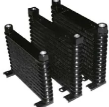
Fig. 1 Condenser or evaporator of air conditioner is a single-pipe heat exchanger
Fig. 2 Radiator applied in vehicles and inside buildings is a single-pipe heat exchanger
A More Accurate Total Heat Transfer Rate
Method of the Single-pipe Heat Exchanger
Considering Heat Radiation
Shih-Shih Ku, King-Leung Wong, IAENG member, Ho-Chiao Chuang
II. PROBLEM FORMULATION
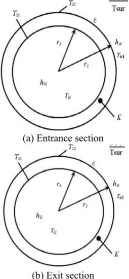
The condenser or evaporator of an air conditioner is a good application example of single-pipe heat exchanger as shown in Fig. 1. The radiators applied to vehicles and to heating system inside buildings is other application example of single-pipe heat exchanger as shown in Fig. 2. Fig. 3 shows that an circular single-pipe heat exchanger is with length L, inner radius r1, outer radius r2, wall conductivity K, outer surface emissivity ε, internal fluid with convection heat transfer coefficient hi1 and temperature Ti1 at entrance section, convection heat transfer coefficient hi2 and temperature Ti2 at exit section, respectively; and it is exposed to ambient air with convection heat transfer coefficient ho, ambient air temperatures To1 at entrance section and To2 at exit section, respectively . Practically, hi1 =hi2= hi can be assumed. The surroundings temperature is Tsur. The outer surface area of heat exchanger is much smaller than that of surroundings.
(a) Entrance section
[image:2.595.106.234.278.554.2](b) Exit section
Fig. 3 A single-pipe heat exchanger and its relative parameters at entrance and exit sections
A. LMTD method neglecting the influence of heat radiation
While the influence of outer surface heat radiation is not considered, the log mean temperature difference (LMTD) method [1-10] is conventionally used to calculate the total heat transfer rate of heat exchangers. From the relative temperatures of entrance and exit sections as shown in Fig. 3, LMTD can be expressed as:
)
(
)
(
ln
)
(
)
(
LMTD
2 2 1 1 2 2 1 1 o i o i o i o iT
T
T
T
T
T
T
T
(1)L
r
h
KL
r
r
L
r
h
R
o i th 2 1 2 12
1
2
ln
2
1
(2)The total heat transfer rate of the long circular pipe neglecting the heat radiation by LMTD method is:
th
R
LMTD
Q
(3) The unit length heat transfer rate, q1, at the entrancesection is: 2 1 1 1 1 1
2
1
r
h
T
T
L
R
T
T
q
o o s th o i
(4)The unit length heat transfer rate, q2,at the exit section
is: 2 2 2 2 2 2
2
1
r
h
T
T
L
R
T
T
q
o o s th o i
(5)The values of total heat transfer rate Q, the average surface temperature at the entrance section Ts1, the average surface
temperature at the exit section Ts2 , can obtained from Eqs.
(1)~(5) under the given values of hi,, ho,r1, r2, K, L, Ti1, Ti2 ,To2 and L
B. Situations considering the influence of heat radiation
While the influence of outside surface heat radiation is considered, the complete unit length heat transfer rate at the entrance sectionis:
K
r
r
r
h
T
T
q
i o i a
2
ln
2
1
1 2 1 1 1 1
(6)The unit length surface convective heat transfer rate at the entrance section is:
q
c1
h
o2
r
2(
T
21
T
o1)
(7)The unit length surface radiation heat transfer rate at the entrance section is:
q
r1
2
r
2(
T
214
T
sur4)
(8) The following equation is obtained from heat balance atthe entrance section:
1 1
1 c r
a
q
q
q
(9) The values of qa1, qr1, qc1 andT21can obtained from Eqs.(6)~(9) under the given values of hi1,ho,r1, r2, K, Ti1,To1, ε
and Tsur.
Similarly, the complete unit length heat transfer rate at the exit sectionis:
r
r
T
T
q
i oa
ln
1
2 2 2 2
the exit section is:
q
c2
h
o2
r
2(
T
22
T
o2)
(11). The unit length surface radiation heat transfer rate at the exit section is:
q
r2
2
r
2(
T
224
T
sur4)
(12)The following equation is obtained from heat balance at the exit section:
2 2
2 c r
a
q
q
q
(13) The values of qa2, qr2, qc2 andT22 can obtained fromEqs. (10)~(14) under the given values of hi2 , ho , r1, r2 , K, Ti2 , To2 , εand Tsur.
The total heat transfer rate of the single-pipe heat exchanger considering the heat radiation by log mean heat transfer rate (LMHTR) method is defined as:
L
q
q
q
q
a a a a a 2 1 2 1ln
Q
(14)The above LMHTR method (considering heat radiation) under the same concept as LMTD method (neglecting heat radiation) is developed in this study. While the heat radiation is not considered, assume the temperatures
Ti1 and To1 keep constant at the entrance section, and Ti2and To2 keep constant at the exit section, then the following
relations can be obtained in the situation of neglecting heat radiation (orε=0):
L
R
T
T
q
q
th o i a 1 1 1 1
(15)L
R
T
T
q
q
th o i a 2 2 2 2
(16)Then the following relation between LMTD method and LMHTR method in the situation of neglecting heat radiation (or ε=0) can be proven:
L
L
R
T
T
L
R
T
T
L
R
T
T
L
R
T
T
L
q
q
q
q
th o i th o i th o i th o i a a a a a)
(
)
(
ln
)
(
)
(
ln
Q
2 2 1 1 2 2 1 1 2 1 2 1
th th o i o i o i o i R LMTD R T T T T T T T T ( ) ) ( ln ) ( ) ( 2 2 1 1 2 2 1 1 (17)from LMTD method and LMHTR method in the situation of neglecting heat radiation (or ε=0) are the same value.
The error of total heat transfer rate generated by neglecting heat radiation effect (whileε≠0) is defined as:
%
100
)
(
QR
a a
Q
Q
Q
(18) The error of average surface temperature at the entrance section generated by neglecting heat radiation is:%
100
)
(
TR
21 21 1 1
T
T
T
s (19)Theerror of average surface temperature at the exit section generated by neglecting heat radiation is:
%
100
)
(
TR
22 22 2 2
T
T
T
s (20)III. The reliability of the numerical results
The nature of results of heat equation for a circular single-pipe heat exchanger is one-dimension exact solution. The exact numerical heat transfer results of a circular pipe can be obtained by any one-dimensional computer code (such as LabVIEW programming in this study). The computer aid results are obtained within half second computing time by a common PC.
In order to check if the numerical results are reliable, the following checking methods are used:
(1). Let outer surface emissivity ε=0, make sure if the results of QR=0.
(2).Let surface emissivity ε=1, outer convection coefficient ho =100,000Wm-2K-1, make sure if the results of
[image:3.595.318.539.482.679.2]QR close to zero.
Fig. 5 The relations among surface temperature errors, TR1 and TR2, and emissivity, ε, for a heater
IV. Results and discussions
The following practical examples is use to demonstrate what the differences and relationships of the results between the LMTD method and LMHTR method are.
Example 1:
A single-pipe heater constructed by a circular pipe with conductivity K=77 Wm-1K-1 and various surface
emissivities ε=0, 0.1, 0.2, 0.3, 0.4, 0.5, 0.6, 0.7, 0.8, 0.9 and 1 (refer Table 1), length L=10m, inner radius r1=198mm,
outer radius r2=200mm, the hot water is flowing inside the
heater with entrance temperature Ti1=65℃ and convective
heat coefficient hi=30 and 5000 Wm-2K-1 (refer Table 2),
with exit temperature Ti2=60℃, the ambient air at the
entrance section with temperature To1=22℃and convective
heat coefficient ho=8 Wm-2K-1 (refer Table 2 and practical
application in air conditioning), the ambient air at the exit section with temperature To2=24℃, and the heater is
located in a big room with wall or surrounding temperature
Tsur =20℃. The results are shown in Table 3 and Figs. 4-5.
Example 2:
A chiller constructed by a circular pipe with conductivity KA=77 Wm-1K-1 and various surface
emissivities ε=0, 0.1, 0.2, 0.3, 0.4, 0.5, 0.6, 0.7, 0.8, 0.9 and 1 (refer Table 1), length L=10m, inner radius r1=198mm, outer
radius r2=200mm, the cold water is flowing inside the heater
with entrance temperature Ti1=7℃ and convective heat
coefficient hi=30 and 5000 Wm-2K-1 (refer Table 2), with
exit temperature Ti2=12℃, the ambient air at the entrance
section with temperature To1=24℃and convective heat
coefficient ho=8 Wm-2K-1 (refer Table 2 and practical
application in air conditioning), the ambient air at the exit section with temperature To2=26℃, and the heater is located
in a big room with wall or surroundings temperature Tsur
=30℃. The results are shown in Table 4 and Figs. 6-7.
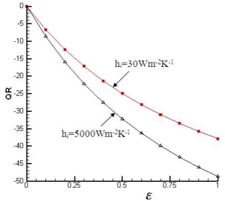
Fig. 6 The relations between heat transfer rate error, QR, and emissivity, ε, for a chiller
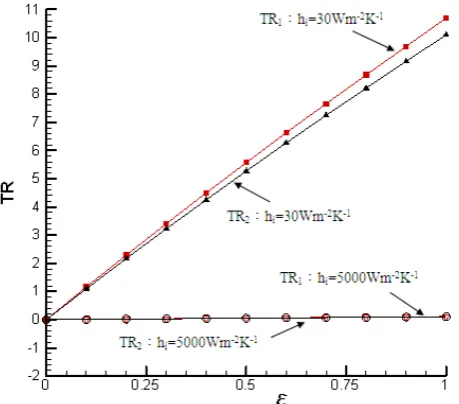
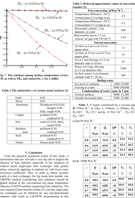
From Table 3-4 and Figs. 4-7 show that in situations of
ε=0 , QR=0, TR1=0 and TR2=0; the greater theεis, the
greater the absolute values ofQR, TR1 and TR2 will be; the
greater the hoare, the smaller the TR1 and TR2 will be; while
ε>0, all the QR are negative, it means in the situations of neglecting heat radiation, the smaller absolute values of heat transfer rate,
Q
, will be obtained (i.e.,Q
<Q
a ), and most absolute values of QR are so big and out of theengineering acceptable range; and in situations ofε>0, the greater the values of hi, the greater the absolute values of QR
will be, but the smaller the TR1 and TR2 will be; for the
heater, TR1 and TR2 are positive (i.e., Ts1> T21 andTs2> T22 ),
it means in the situations of neglecting heat radiation, the greater surface temperatures (over-prediction of hot surface) will be obtained; for the chiller, TR1 and TR2 are negative
(i.e., Ts1< T21 andTs2< T22 ), it means in the situations of
neglecting heat radiation, the smaller surface temperatures (over-prediction of cold surface) will be obtained, these predictions may lead to misjudge the condensation occurred on the surface.
[image:4.595.53.283.55.257.2]Fig. 7 The relations among surface temperature errors, TR1 as well as TR2, and emissivity, ε, for a chiller
Table 1 The emissivities ε of various metal surfaces [1]
Gold 0.02 Silver 0.02 Aluminum Weathered=0.83;Foil
(bright)=0.04 Disk, rough=0.96 Copper polished=0.05;
oxidized=0.78
Iron cast(ox)=0.64; sheet,
rusted=0.69 Stainless
steel polished=0.16; oxidized=0.85
Steel polished=0.07;
oxidized=0.79 Nickel Electro pole=0.05
V. Conclusion
From the practical numerical results of this study, it demonstrates that one will take a very big risk to neglect the influence of heat radiation especially in the situations of oxidized metal single-pipe heat exchanger with greater surface emissivity applying in ambient air with lower outer convection coefficient. Thus, in order to obtain accurate results of a heat exchanger, the log mean heat transfer rate (LMHTR) method (considering heat radiation) should be applied instead of the conventional log mean temperature difference (LMTD) method (neglecting heat radiation). The exact numerical heat transfer results of a circular single-pipe heat exchanger can be obtained by any one-dimensional computer code (such as LabVIEW programming in this study) within half second computing time by a common PC
transfer [1]
Free convection, h(Wm-2K-1) Temperature difference =30 ℃
Vertical plate 0.3 in high in air 4.5 Temperature difference =30 ℃
Vertical plate 0.3 in high in air 6.5 Horizontal cylinder, 2 cm
diameter, in water 890
Heat transfer across 1.5 cm
vertical air gap with TD=60 ℃ 2.64
Forced convection
Air flow at 2 m/s over 0.2-m
square plate 12
Air flow at 35 m/s over 0.75-m
square plate 75
Air at 2 atm flowing in 2.5 cm
diameter tube at 10 m/s 65 Water at 0.5 kg/s flowing
in 2.5 cm diameter tube 3500 Air flow across 5 cm diameter
cylinder with V= 50 m/s 180
Boiling water
In a pool or container 2500–35,000 Flowing in a tube 5000-100,000
Condensation of water vapor in 1 atm
[image:5.595.51.523.44.733.2]Vertical surfaces 4000–11,300 Outside horizontal tubes 9500–25,000
Table 3. A heater constructed by a circular pipe with
K=77Wm-1K-1, L=10m, r
1=198mm, r2=200mm, Ti1=65℃,
Ti2=60℃, To1=22℃ and ho =8 Wm-2-K-1 ; To2=24℃ and;
Tsur =20℃
(a) hi=30 Wm-2K-1
ε Q
Watt
Qa
Watt
QR %
TS2
℃
T22
℃
TR2 %
0.0 3119 3119 0.0 52.4 52.4 0.0
0.6 3119 4342 -28 52.4 49.3 6.3
0.7 3119 4519 -31 52.4 48.8 7.3
0.8 3119 4692 -34 52.4 48.4 8.2
(b) hi =5000 Wm-2K-1
ε Q
Watt
Qa
Watt
QR %
TS2
℃
T22
℃
TR2 %
0.0 3953 3953 0.0 59.9 59.9 0.0
0.6 3953 6205 -36 59.9 59.8 0.06
0.7 3953 6579 -40 59.9 59.8 0.07
0.8 3953 6956 -43 59.9 59.8 0.08
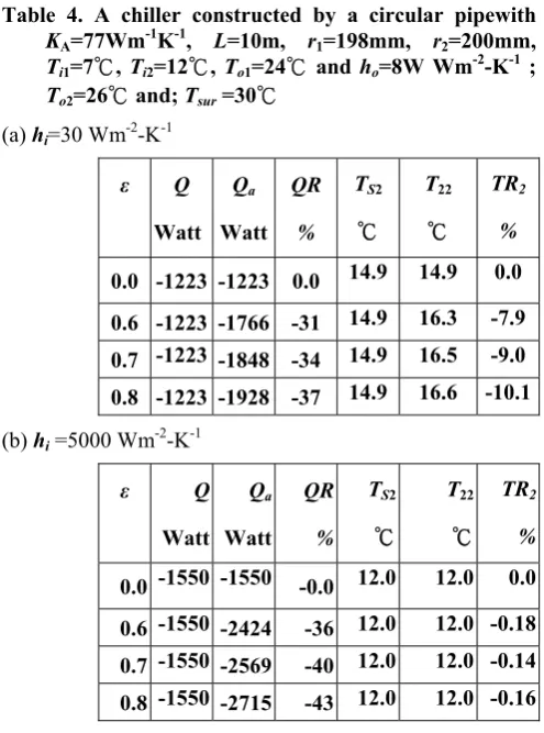
[image:5.595.307.552.467.733.2]Table 4. A chiller constructed by a circular pipewith
KA=77Wm-1K-1, L=10m, r1=198mm, r2=200mm,
Ti1=7℃, Ti2=12℃, To1=24℃ and ho=8W Wm-2-K-1 ; To2=26℃ and; Tsur =30℃
(a) hi=30 Wm-2-K-1
ε Q
Watt
Qa
Watt
QR %
TS2
℃
T22
℃
TR2 %
0.0 -1223 -1223 0.0 14.9 14.9 0.0
0.6 -1223 -1766 -31 14.9 16.3 -7.9
0.7 -1223 -1848 -34 14.9 16.5 -9.0
0.8 -1223 -1928 -37 14.9 16.6 -10.1
(b) hi =5000 Wm-2-K-1
ε Q
Watt
Qa
Watt
QR %
TS2
℃
T22
℃
TR2 %
0.0 -1550 -1550 -0.0 12.0 12.0 0.0
0.6 -1550 -2424 -36 12.0 12.0 -0.18
0.7 -1550 -2569 -40 12.0 12.0 -0.14
0.8 -1550 -2715 -43 12.0 12.0 -0.16
Acknowledgment
The authors would like to acknowledge the National Science Council of Taiwan, R.O.C.. This investigation is completed under the support of the project NSC
100-2221-E-168-035.
References
[1] R.A. Bowman, Muller A.C. and Nagle W.M., Mean Temperature Difference in heat exchanger design, Transactions of the ASME 62 (1940), pp.283.
[2] R.A. Stevens, J. Fernandes and J.R. Woolf, Mean Temperature Difference in one, two, three pass cross-flow heat exchangers, Transactions of the ASME 79 (1957), pp.287-297.
[3] J.P. Holman , Heat transfer, Eighth SI Metric Edition, McGraw-Hill Inc., (2001), pp.7~39 and pp.638~642. [4] M.N.Ozisik, Heat transfer, A basic approach, McGraw
Hill Book Company, (1998), pp.59-62.
[5] E.G. Pita, Air conditioning principles and system, 3rd
edition, Prentice Hall, (1998), pp.252-256.
[6] R.J. Dossat, Principles of refrigeration, 3rd edition,
Prentice Hall, (1991), pp.167-178.
[7] A.P. Fraas, Heat exchanger design, 2 rd edition, New York, John Wiley & Sons, 1989.
[8] E.U. Schlunder, Heat exchangers design handbook, Washington D.C., Hemisphere, 1982.
[10]. G. Walker, Industrial Heat exchangers, Washington D.C., Hemisphere, 1982
[11] K.L. Wong, W.L. Chen, Y.C. Chiu, Inaccuracy of heat transfer characteristics of a metal pipe neglecting heat radiation effect in ambient air, Proceedings of The
2012 International Conference on Energy and