UPQC Implements The 3-Phase Shunt And Series Active Power
Filter To Compensate Current And Voltage Harmonics
J. Sunitha1, M. Ramesh2 1
M. Tech scholar, Department of EEE, S.R Engineering College, Warangal, T.S, India 2
Assistant Professor, Department of EEE, S.R Engineering College, Warangal, T.S, India
Abstract:- This paper presents the three phase shunt
and series active power filter in order to reduce the current and voltage harmonics. To implement Unified Power Quality Conditioner (UPQC) control algorithm two control strategies p-q instantaneous power and d-q synchronous frame theory are used to mitigate the problems of power quality caused due to nonlinear loads. Both control theories performances are carried out and compared under nonlinear loads. The performance of UPQC with two control strategies has been tested in the Matlab/Simulink environment. The simulation results showed better performance for harmonic problems.
Key words:- Power Quality, UPQC, harmonics,
active power filter.
I. INTRODUCTION
Nonlinear loads connected to electric energy distribution networks generate harmonic pollution. Such nonlinear loads drain currents with varying degree of harmonic contents. The harmonic current components do not represent useful active power due to the frequency mismatch with the grid voltage. However, the circulation of harmonic currents through feeders and protective network elements produces Joule losses and electromagnetic emissions that might interfere with other devices connected to the distribution network. This affects the electrical performance of control and communication systems involved with the protective elements. Several other harmful effects are observed as presented in [1], [2].
Traditionally passive filters have been used to eliminate current harmonics of the supply network. However, these devices suffer from resonance. Active filters were developed to mitigate problems of passive filters [3]–[5]. They are more effective in harmonic compensation and have good performance. To deal with both current and voltage harmonic problems simultaneously, the most advanced mitigating device i.e. unified power quality conditioner (UPQC) has been developed [6]-[7]. To ensure both the load voltage and the supply current sinusoidal, the UPQC has a combination of series and shunt active power filters
sharing a common dc link. The two active power filters (APF’s) have different functions; where the series APF is operated as a controlled voltage source to suppress and isolate voltage harmonics, meanwhile shunt APF acts as a controlled current source to compensate the current harmonics [7].
In this paper a comprehensive analysis of UPQC using two (p - q and d - q theory) control theories for derivation of reference signals has been done. These reference signals are then compared with sensed three phase input signals in a hysteresis controller for generation of switching signals. The UPQC is used for harmonic elimination and simultaneous compensation of voltage and current, which improve the PQ, offered for other harmonic sensitive loads at the point of common coupling (PCC).
II. UPQC SYSTEM CONFIGURATION
One of the foremost custom power devices that are competent of alleviating the consequence of PQ problems at the non linear load is the UPQC. In addition to removal of harmonics, recompense for reactive power, load current unbalance, source voltage sags, source voltage unbalance and power factor correction are provided by UPQCs. Basic configuration of UPQC consists of two voltage source inverters sharing DC link capacitor as shown in Fig 1. One of the voltage source inverters acts as a series APF and the other as shunt APF, which are connected back to back through dc link capacitor.
The series APF which is connected between the source and PCC using three single phase series transformers has the capability of compensating the voltage harmonics, voltage flicker and improving voltage regulation [8]. A small rated capacity capacitor filter is connected across the secondary of each series transformers to eliminate the high switching ripple content in the series APF injected voltage [9]. The shunt APF has capability of suppressing the current harmonics, compensating reactive power, negative sequence current and regulation of the dc link voltage between both APF’s [8]. The shunt APF is connected through a small rated capacity inductive filter in order to eliminate the high switching ripple content in the shunt APF injected current. The implemented control algorithm mainly consists of the generation of three phase reference voltages at load terminals and the reference source currents. Control strategies to generate the reference signals of the voltage and current of UPQC have been developed to mitigate the harmonic voltage and currents [7]-[8]. The most common are the instantaneous power (p - q) theory [7], modified p – q theory [8], and synchronous reference frame (d - q) theory [9].
III. UPQC CONTROL STRATEGY
The control unit is the most important part of the UPQC system. Rapid detection of disturbance signal with high accuracy, fast processing of the reference signal and high dynamic response of the controller are the prime requirements for desired compensation. Control unit can be considered as three separate steps: series inverter, shunt inverter and DC link voltage control. Series inverter control for voltage reference signal generation and shunt inverter control for current reference signal generation. The control methods used to extract reference signals are based on frequency and time domain techniques. The compensation in frequency domain is based on Fourier analysis of voltage and current signals to extract reference signals whereas compensation in time domain is based on instantaneous derivation of reference signals in terms of voltage and current signals from distorted voltage and current signals, which consist of simple algebraic calculations and transformations. The synchronous reference frame (d - q) theory is used for series APF where as instantaneous power (p - q) theory is used for shunt APF to generate reference signals which then compared with sensed three phase input signals in hysteresis controller to generate switching signals.
The series APF is controlled in such a way that it injects the voltages which cancel out the distortions and unbalance exists in the supply voltages ( , , ) in order to make the voltages at the PCC ( , , ) perfectly balanced and sinusoidal. The SRF-based control method is one of the most conventional and the most practical methods. The SRF method presents excellent characteristics but it requires decisive PLL techniques. The proposed SRF control method uses (a – b – c to d – q – 0) whose direct (d) and quadrature (q) axes rotate in space at the synchronous speed given by = 2 , where is supply frequency. If is the transformation angle, then the voltage transformation from a-b-c to d-q-0 frame is calculated as:
0
=23
⎣ ⎢ ⎢ ⎢ ⎢
⎡sin sin −23 sin +23
cos cos −23 cos +23 1
2
1 2
1 2 ⎦⎥
⎥ ⎥ ⎥ ⎤
(1)
=
⎣ ⎢ ⎢ ⎢
⎡ sin cos 1
sin −23 cos −23 1
sin +23 cos +23 1⎦⎥ ⎥ ⎥ ⎤
0
(2)
The control strategy for the series APF is shown in Fig. 2 where the SRF theory is used. The
and voltages are sent through low pass filter (LPF) for filtering the harmonic components of the supply voltage, which allows only the fundamental frequency components. The LPF is fifth order low pass butter worth filter used for eliminating the higher order harmonics. In Fig. 2 the phase locked loop (PLL) is used to achieve synchronization with the supply as the supply voltage is unbalanced and/or distorted. After inverse transformation in a-b-c coordinates the computed voltages from (2) are given to the hysteresis controller along with the sensed three phase PCC voltages . The output of the hysteresis controller is switching signals, used to control the six switches of VSI of the series APF. The hysteresis controller generates the switching signals such that the voltage at the PCC becomes the desired sinusoidal reference voltage. Therefore, the injected voltage across the series transformer by series APF through the ripple filter cancels out the harmonics and unbalance present in the supply voltage.
B. Shunt APF Reference Signal Generation
The control strategy to compensate harmonic currents used in this work is based on the p-q theory for shunt APF as shown in Fig 3. The three phase load currents , and are transformed from three phase (a-b-c) reference frame to (α-β-0) by using Clarke transformation which is given below
= 23
⎣ ⎢ ⎢ ⎢ ⎢ ⎢ ⎡1
√2 1 √2
1 √2 1 −12 −12
√3 2 √32 ⎦⎥
⎥ ⎥ ⎥ ⎥ ⎤
(3)
0
= 23
⎣ ⎢ ⎢ ⎢ ⎢ ⎢ ⎡1
√2 1 √2
1 √2 1 −12 −12
√3 2 √32 ⎦⎥
⎥ ⎥ ⎥ ⎥ ⎤
(4)
The source side instantaneous real and imaginary power components can be calculated by using (4) and (5). The instantaneous real and imaginary powers include both oscillating and average components given by (6). Average components of p and q consist of positive sequence components ( and ) of source current. The oscillating components ( and ) of p and q
include harmonic and negative sequence components of source currents.
= − (5)
In order to reduce neutral current (for 3-phase , 4 wire system), 0is calculated by using average and oscillating components of imaginary power and oscillating component of the real power; as given in (7) if both harmonic and reactive power compensation is required.
0= 0∗ 0
= + (6)
Fig.3. Block diagram of shunt APF reference signal generator
The ∗ , ∗ and 0
∗
∗ = 1
+ ∗
− + 0+
(7)
∗ ∗
∗ =
2 3
⎣ ⎢ ⎢ ⎢ ⎢ ⎢ ⎡1
√2 1 1 √2 −
1 2
√3 2 1
√2 − 1 2 −√32 ⎦⎥
⎥ ⎥ ⎥ ⎥ ⎤
0 ∗ ∗
∗ (8)
C. DC link Control
The DC voltage regulator shown in Fig. 4 is used to generate a control signal to keep the DC voltage constant and self regulated which may vary because of abnormal operation and transients. The dc link voltage is sensed at a regular interval and is compared with reference signal ∗ . The error signal is processed in a PI controller. This signal forces the shunt active filter to draw additional active current from the network to compensate losses in the power circuit of UPQC. The parameters of PI Controller [G(s) = + ⁄ ] plays an important role in DC voltage control system response.
Fig.4. Control system of DC link
Too much increase in proportional gain leads to instability in DC voltage control system and reduction in ( ) decreases the responding speed of control system. Integral gain ( ) of controller corrects the steady state error of the DC voltage control system. If this gain value is selected large, the resulted error in steady state is corrected faster and increase in its value ends in overshoot in system response.
IV. SIMULATION RESULTS
Fig. 5 shows the block diagram of the proposed UPQC, the simulation is performed using MATLAB – Simulink software and SimPower System Toolbox. The performances of UPQC are evaluated in terms of voltage and current harmonics mitigation, sags, swells and voltage unbalances compensation. A 3-phase diode bridge rectifier with RL load acts as nonlinear load which
is connected to AC mains to demonstrate the effectiveness of the UPQC with the proposed method. The UPQC circuit parameters used in MATLAB/Simulink are given in Table I.
In the simulation studies, the results are specified before and after the operation of the UPQC system. The voltage and current harmonic compensation capability of the proposed UPQC control method is shown in Table II as total harmonic distortion (THD) levels.
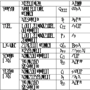
TABLE – I System Parameters
Parameters Value
Supply Fundamental
voltage 440V
Frequency 50Hz
Load Diode rectifier load
inductance 10mH
Diode rectifier load
resistance 10
Ω
DC-link Reference voltage ∗ 600V
Capacitance 2200µF
Shunt
APF Filter inductanceSwitching ℎ 1mH
frequency 5 kHz
Series
APF Filter inductanceFilter capacitance 0.4mH25µF Switching
frequency 5 kHz
TABLE II THD Levels of Current and Voltage Waveforms at PCC
THD (%) Without
UPQC p-q theoryWith UPQCd-q theory
Current 20.16 1.52 1.52
Fig.5. Simulation Model of UPQC
Fig.6. Simulink model of controller
The Simulink model of shunt APF and series APF controllers are as shown in Fig.6. Load
voltages, current source waveforms with and without UPQC are shown in Fig.7.
(a) Load Voltage without UPQC
(b) Source Current without UPQC
(c) Load Voltage with UPQC
Fig.7. Load Voltages, Source Current with and without UPQC
(a)
(b)
Fig.8. Harmonic spectrum (a) Without UPQC and (b) With UPQC of source current
The THD of the supply current is brought down from 20.16% to 1.52% it is shown in Fig.8.The effectiveness of the proposed UPQC has been demonstrated in maintaining the three-phase load voltages balanced and sinusoidal, moreover the proposed system does not show any significant effect of disturbance type present in the utility voltages on its compensation capability and the load voltage under all voltage is maintained constant, balanced and sinusoidal.
V. CONCLUSION
To enhance the power quality by reducing the source current harmonics and improve the voltage delivered to sensible and critical loads, a UPQC configuration has been presented in this paper. The control strategy adopted is based on the instantaneous power method for the shunt APF and synchronous reference frame detection method for the series APF. The developed model is validating through simulation results using Matlab-Simulink software and SimPower System toolbox. The control algorithm of UPQC has been observed to be satisfactory for various power quality improvements like voltage harmonics mitigation, current harmonic mitigation, voltage sag, swell and unbalance compensation.
REFERENCES
[1] M. Cirrincione, M. Pucci, G. Vitale, and A. Miraoui, “Current harmonic compensation by a single-phase shunt active power filter controlled by adaptive neural filtering,” IEEE Transactions on Industrial Electronics, vol. 56, no. 8, pp. 3128 3143, 2009.
[2] P. Salmeron and S. Litran, “Improvement of the electric power quality using series active and shunt passive filters,” IEEE Transactions on Power Delivery, vol. 25, no. 2, pp. 1058– 1067, 2010.
[3] H. Hu, W. Shi, Y. Lu, and Y. Xing, “Design considerations for DSPcontrolled 400 Hz shunt active power filter in an aircraft power system,” IEEE Trans. Ind. Electron., vol. 59, no. 9, pp. 3624–3634, Sep. 2012.
[4] X. Du, L. Zhou, H. Lu, and H.-M. Tai, “DC link active power filter for three-phase diode rectifier,” IEEE Trans. Ind. Electron., vol. 59, no. 3,pp. 1430–1442, Mar. 2012.
[5] M. Angulo, D. A. Ruiz-Caballero, J. Lago, M. L. Heldwein, and S. A. Mussa, “Active power filter control strategy with implicit closedloop current control and resonant controller,” IEEE Trans. Ind. Electron., vol. 60, no. 7, pp. 2721– 2730, Jul. 2013
[6] H. Akagi, E. H. Watanabe, and M. Aredes, “Instantaneous power theory and applications to power conditioning,” Hoboken, NJ: Wiley-IEEE Press, Apr. 2007.
[7] H. Fujita and H. Akagi, “The unified power quality conditioner: The integration of series and shunt active filters,” IEEE Trans. Power Electron., vol. 13, no. 2, pp. 315–322, Mar. 1998.
[8] Teke, L. Saribulut and M. Tümay, “A novel reference signal generation method for power quality improvement of unified power quality conditioner,” IEEE Trans. Power Del., Vol. 26, no. 4, pp. 2205-2214, Oct. 2011.
[9] Tan Zhili, Li Xun, Chen Jian, Kang Yong and Duan Shanxu, “A direct control strategy for UPQC in three-phase four-wire system,” Proc. IEEE Conf. on Power Electronics and Motion Control 2006, vol.2, pp.1-5.
[10] V. Khadkikar, “Enhancing Electric Power Quality Using UPQC: A comprehensive overview,” IEEE Trans. Power Electron. Vol. 27, No.5, pp.2284 – 2297, May 2012.
J. SUNITHA currently pursuing her M.Tech in Power Electronics from S.R Engineering College, Warangal, Telangana, India, affiliated to JNTU, Hyderabad. She has done her B.Tech from Abdulkalam Institute of Technological sciences, affiliated to JNTU, Hyderabad, Telangana, India and her fields of interest include Power Systems.