Performance Enhancement of Wearable Antenna
Using High Impedance Surfaces
Shahid Bashir
1, M Salman Khan
1, Khadim Ullah Jan
2, Sadiq Ullah
21
Department of Electrical Engineering, University of Engineering & Technology, Peshawar, Pakistan
2
Department of Telecomm Engineering, University of Engineering & Technology, Peshawar, Pakistan [email protected], [email protected]
Abstract: This paper presents a novel textile wearable antenna
that has been designed to operate at Wi-Fi bands of 2.4GHz & 5.8GHz. Antenna performance in free space environment showed Gain of 1.8dBi at 2.4GHz and 4.5dBi at 5.8GHz. However, performance deteriorated when antenna was operated near human body which is lossy and complex in nature. For mitigating the human body effect on antenna performance, high impedance surface (HIS) was designed and integrated with this textile antenna. Due to shielding effect of HIS, antenna Gain increased to 8dBi at 2.4GHz and 9dBi at 5.8GHz. The SAR values were also reduced to 0.682W/Kg at 2.4GHz and 0.0692W/Kg at 5.8GHz for 10g tissue. The proposed antenna was also tested under bending and crumpling conditions. It was observed that antenna performance was not significantly deteriorated. The proposed textile antenna can have exciting applications in emerging wearable technologies.
Keywords: Body Area Networks, Wearable antenna, High
Impedance surface, Specific Absorption Rate, EBG, AMC
1.
Introduction
Body centric wireless communication is one of the leading research areas in 4G mobile communications. In body area network (BAN) the communicating devices are all placed on or close to human body. These networks are increasingly finding applications in military and civilian domain [1]. It is a challenging task to improve the performance of these networks due to the unpredictable and changing channel behaviour. The antenna performance is one of the critical parameter in the overall network performance. As a result, a new antenna design concept in the form of wearable antenna has been proposed by many antenna designers and researchers around the globe [2-5].
A wearable antenna should be made of flexible wearable material, be light weight, inexpensive and easy to install. The availability of conductive fabrics like Flectron, Zelt and nonconductive fabrics like cotton, jeans, silk make it possible to design wearable textile antenna as part of clothing and be called textile antenna [6]. Numerous papers have been published that reported the design, fabrication and application of single and dual band wearable antennas [7-9]. The challenge in wearable antenna design is the close presence of lossy human body which can absorb radiation causing increase in Specific Absorption Rate (SAR) as well as it can degrade antenna gain and efficiency [10]. Recently integration of these antennas with Electromagnetic Band Gap (EBG) has been performed [11-17]. These EBGs can reduce the backward radiation from the antenna which results in low Specific Absorption Rate (SAR) due to reduction of energy absorbed by human body. However, the performance of these
wearable antennas degrade when operated on a non-uniform human body due to crumpling effect [18].
In this paper it is shown that performance of wearable antenna is highly affected by human body and to overcome this, necessity of EBG is demonstrated. For this purpose, first a novel dual band wearable PIFA has been designed. The antenna is then integrated with a dual band EBG structure which behaves as HIS. Afterwards the on-body performance of the antenna is evaluated under crumpling with and without HIS.
This paper is organized as follow. In section 2 the related work in this area has been critically analyzed. In section 3 the design and performance of dual band wearable PIFA in free space is demonstrated. In section 4 the design of dual band HIS is explained along with its main features. Section 5 explains the integration of antenna with HIS along with the comparison of different parameters of antenna with and without HIS. The on body performance of HIS antenna is presented in Section 6, followed by the conclusions in section 7. All the design and simulations were performed in CST Microwave Studio.
2.
Related work
communications due to their broadside radiation patterns, but they have narrow bandwidth. Recently EBG and Artificial Magnetic Conductor (AMC) ground plane have been incorporated in the wearable antenna design [30]; such structure can isolate the antenna from its surrounding and can decrease the SAR dramatically. The in phase reflection and electromagnetic bandgap properties exhibited by these artificial structure has started exciting developments in antenna design. Initially mushroom type structure was proposed [31] however its implementation was difficult due to requirement of vias.
Then planar type structures were introduced [32,33]. They are simple to design and implement however they tend to have large size which limits their use in portable devices. This led to research to reduce the size of these EBG structures [34,35]. Many researchers proposed the use of these EBG structures for wearable antennas [36]. However, these EBG structures were rigid and brittle and thus considered not suitable for wearable applications. With the availability of flexible conducting and dielectric materials many researchers are now trying to propose wearable EBG structures.
3.
Design of Dual Band Wearable Antenna
Planar types of antennas are desirous in case of wearable applications because of its ease of design and on-body integration. For this purpose, a novel dual band wearable PIFA is designed from its single band version that was initially presented in [18]. Some structural modifications have resulted in dual resonances near 2.4GHz and 5.8GHz simultaneously. The geometrical configuration of designed antenna is given in Figure 1.
(a)
(b)
Figure 1. Structure of Dual Band Textile Antenna (a) Top
View (b) Side View
Two different radiating elements are used here, one longer arm with length of 27.2 mm, and second is shorter arm with length of 9.8 mm. The longer arm resonates at 2.4GHz and shorter arm resonates at 5.8GHz. Micro strip transmission line having characteristic impedance of 50Ω with width of 25
mm and length of 5 mm provides feed to the antenna. A shorting pin is used to connect left end of the antenna with ground plane on opposite side. Here a partial ground plane has been employed that covers area equal to length of transmission line on opposite side. Separation between shorting pin and transmission line can be adjusted to change the antenna input impedance. Overall dimension of the antenna is 35 x 40 x 1.1 mm which is small enough to be worn easily on human bicep. Commonly available Felt has been used as a substrate that has a thickness of 1.1mm with dielectric constant of 1.38 and loss tangent of 0.02. Conducting part of the antenna is designed using Zelt that has a thickness of 0.06 mm and conductivity of 1e + 006S/m. Return loss versus frequency plot shows two resonances at 2.4GHz and 5.8GHz with values of -17 dB and -21dB respectively (Figure 2). The -10dB impedance bandwidth is 9.2% at 2.4GHz and 4.3% at 5.8GHz.
0 1 2 3 4 5 6 7
-30 -25 -20 -15 -10 -5 0
Frequency / GHz
R
et
u
rn
L
o
ss
(
d
B
)
Figure 2. Textile antenna Return loss
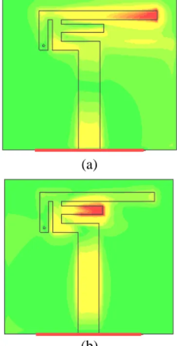
Distribution of surface current at both operating frequencies is presented in Figure 3 that clearly shows that maximum current flows through longer arm at 2.4GHz and at 5.8GHz it flows through the shorter arm.
(a)
(b)
Figure 3. Distribution of surface current of textile antenna
Lengths of radiating elements are able to vary the corresponding frequency. Figure 4 presents variation of resonance at higher band by decreasing length of shorter radiating arm.
0 1 2 3 4 5 6 7
-30 -25 -20 -15 -10 -5 0
Frequency / GHz
R
et
u
rn
L
o
ss
(
d
B
)
9.0 mm Length 9.8 mm Length 9.4 mm Length
Figure 4. Comparison of Return loss for different lengths of
shorter arm
It can be observed that by decreasing length of shorter arm, resonance at 5.8GHz shifted towards higher frequencies while the lower resonant frequency remained unchanged. Here three lengths (9 mm, 9.4 mm, and 9.8 mm) are tested and the operating frequency at higher band is observed to be 5.8GHz, 6GHz and 6.3GHz respectively. Also when the gap between the radiating arms is decreased, impedance matching improves at higher band as can be observed in Figure 5.
0 1 2 3 4 5 6 7
-30 -25 -20 -15 -10 -5 0
Frequency / GHz
R
et
u
rn
L
o
ss
(
d
B
)
1 mm Distance 1.25 mm Distance 1.5 mm Distance
Figure 5. Comparison of Return loss for different distances
between radiating arms
Here the gap is kept 1mm, 1.25mm and 1.5mm and return loss is observed to be -21 dB, -15 dB and -12 dB respectively. The gap is kept 1mm for further evaluations. Figure 6 presents simulated radiation patterns at both the operating frequencies in two different planes i.e. XZ-plane and YZ-plane
(a)
(b)
Figure 6. Fabric antenna radiation pattern at (a) f = 2.4 GHz
(b) f = 5.8 GHz
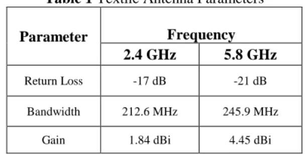
It can be observed that antenna pattern is similar to that of dipole i.e. quasi omni-directional in the XZ plane. Antenna performance parameters are given in Table 1.
Table 1 Textile Antenna Parameters
Parameter Frequency
2.4 GHz 5.8 GHz
Return Loss -17 dB -21 dB
Bandwidth 212.6 MHz 245.9 MHz
Gain 1.84 dBi 4.45 dBi
4.
Design of Dual Band HIS
Wearable antennas are intended to be part of clothing therefore; minimum back radiation is desired from antenna on to the body. Also the designed textile antennas possess no ground plane due to which it will interact with human body. Lossy nature of human body will degrade antenna performance as well. Therefore, incorporation of HIS is essential for such antennas. Suppression of surface waves in a certain band is one of the significant characteristic of HIS. Improvement in antenna performance in terms of gain enhancement and back lobe reduction can be achieved by utilizing this property.
Dual band HIS characteristics can be achieved by generating two different modes. One method is designing two separate resonating structures, one for each mode. Introduction of circular slot in metal patches of mushroom type HIS can achieve this behaviour. Figure 7 present unit cell model of dual band HIS using Felt as substrate having thickness of 2.2 mm.
Since via less planar HIS possess properties of zero phase reflection and band gap. Therefore, no via is used in this design to improve design simplicity and flexibility.
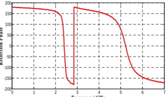
In-phase reflection behaviour for this design is at 2.4GHz and 5.2GHz as shown in Figure 8. The resonance at upper band is due to circular shaped patch while the adjoining square shaped ring results in resonance at lower frequency band. Distribution of surface current at these frequencies is given in Figure 9. Here it can be observed that at 2.4GHz, surface current is concentrated on outer square loop while at 5.2GHz it is concentrated on inner circular patch.
For observing zero reflection behaviour of this HIS model its unit cell is illuminated by normally incident plane wave. Surface of HIS patch is defined as reference plane for calculating phase of reflected wave. Fractional bandwidth of 4.53% and 10.95% is observed at 2.4GHz and 5.22GHz respectively.
0 1 2 3 4 5 6 7
-200 -150 -100 -50 0 50 100 150 200
Frequency / GHz
R
ef
le
ct
io
n
P
h
a
se
Figure 8. Reflection phase response of Dual band HIS
(a) (b)
Figure 9. Surface Current Distribution of Unit Cell (a) f =
2.45GHz (b) f= 5.2GHz
EM wave suppression property of the proposed HIS is determined using micro strip suspended line method. A 3x3 array of HIS having overall size of 102 x 102mm2 is constructed in CST Microwave Studio over which a microstrip line is placed and excited to calculate S21. Due to high impedance of HIS, EM waves are blocked within the band gap. Outside of this bandgap EM waves are able to propagate. Therefore, reduction in S21 indicates location of the band gap as shown in Figure 10.
Band gap is defined for those frequencies for which S21 is less than -10dB. As indicated in Figure 10, S21 decreases to about 47 dB near 1.5GHz and 18dB near 5.6GHz thus having a band gap of 81.8% and 4.3% respectively at these frequencies. In contrast to this, in-phase reflection points for the same structure were at 2.4GHz and 5.22GHz.
1 2 3 4 5 6 7
-70 -60 -50 -40 -30 -20 -10 0
Frequency / GHz
S
2
1
Figure 10. Transmission Response of Dual Band Wearable
HIS
One possible reason for this behaviour can be difference in polarisation of exciting wave being used for extracting in-phase and band gap behaviour of the model. Microstrip line method excites quasi TEM waves that consists of electric field perpendicular to the plane, whereas tangential field component is associated for the case of normally incident waves.
5.
Integration of Textile Antenna with HIS
As previously discussed, reduction in back radiation and as a result less antenna-body interaction can be achieved by incorporating HIS with the antenna. This will enhance the antenna performance over human body. For this purpose, a 3x3 array of HIS ground plane is integrated with the textile antenna. This integration is performed by placing antenna above HIS array. As the textile antenna has no ground plane, therefore separation of 5mm is kept between HIS plane and antenna for proper functioning. The spacing is filled with a layer of Rohacell ( r = 1.006) for preventing the antenna from severe detuning and mismatch. In-phase reflection behaviour is adjusted and optimized so that they overlap with the antenna operating frequencies. Integrated antenna is shown in Figure 11.
Figure 11. Integration of Textile Antenna with Dual Band
EBG
Because of the resonating nature of HIS, mutual impedance coupling between antenna and HIS causes variation in operating frequencies of the antenna. To overcome this variation, HIS structure dimensions are optimized while integrating it to the antenna.
slight shift in central frequency has been observed at lower resonant frequency. Resonance at higher band is comparatively stable with 3.96% bandwidth. Comparing it with antenna without HIS, a 9.2% and 4.3% bandwidth has been observed at 2.4GHz and 5.8GHz respectively. Slight reduction in bandwidth at higher band is observed.
0 1 2 3 4 5 6 7
-30 -25 -20 -15 -10 -5 0
Frequency / GHz
R
et
u
rn
L
o
ss
(
d
B
)
Figure 12. Return loss of HIS Integrated Antenna
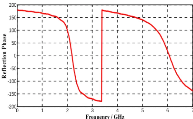
Reflection phase of optimized HIS integrated to the antenna is presented in Figure 13 that has in-phase reflection points at 2.2GHz and 6GHz, which are shifted from those of fabric antenna without HIS. One possible reason behind this could be mutual impedance coupling between antenna and HIS.
0 1 2 3 4 5 6 7
-200 -150 -100 -50 0 50 100 150 200
Frequency / GHz
R
ef
le
ct
io
n
P
h
a
se
Figure 13. Reflection Phase response of textile HIS
6.
On-Body Performance
As textile antennas are designed to operate near human body, therefore performance evaluation of these antennas near human body is essential. Human body presents difficult environment for efficient operation of wearable antennas. This is due to non-homogenous and dynamic human body nature that degrades antenna performance when operated near it. Input impedance of the antenna may change due to interaction with human body. In addition to this, absorption of energy by lossy tissues results in reduction of antenna gain and efficiency. Also due to high value of body tissue’s dielectric constant, the guided wavelength will change resulting in change in operating frequencies of antenna. Another parameter that needs to be evaluated is specific absorption rate (SAR). SAR determines the portion of RF energy absorbed by human tissues. As human body will always be exposed to textile antenna, therefore some energy from back lobes will be absorbed by tissues which is characterized by SAR. To analyse SAR for on-body environment, antenna is placed near human body phantom. SAR is calculated for 10gram tissue with and without HIS ground plane.
Due to curved nature of human body, textile antennas also undergo bending and crumpling. Antenna performance under these conditions may deteriorate and needs to be evaluated for better design.
A homogenous human body phantom was modelled in CST Microwave Studio. This phantom comprises of four layers i.e. Bone, Muscle, Fat and Skin. Electromagnetic properties of these materials are readily available in literature [37]. Because of frequency dependency of EM properties of these materials, average values are used at operating frequencies of 2.4GHz & 5.8GHz. Table 2 summarizes the EM properties of materials used in the phantom model shown in Figure 14.
Table 2 Human Body Electromagnetic Properties
Average EM Properties of Human Body at 2.4 & 5.8GHz
Tissue Name
Conductivity [S/m]
Relative Permittivity
Loss tangent
Bone 0.7695 10.5422 0.3111
Fat 0.1977 5.1201 0.1642
Muscle 3.3333 50.638 0.2795
Skin 2.9519 40.7735 0.3105
Figure 14. Layered model of Human Body Phantom
Operating frequencies of antenna can change due to lossy nature of body when excited in its close proximity. In order to characterise this behaviour, textile antenna is excited near phantom as shown in Figure 15.
Separation between antenna and phantom is varied and antenna performance is evaluated. Return loss with respect to different antenna-body separation is shown in Figure 16.
0 1 2 3 4 5 6 7
-30 -25 -20 -15 -10 -5 0
Frequency / GHz
R
e
tu
rn
L
o
ss
(
d
B
)
0 mm 1 mm 2 mm
Figure 16. Wearable Antenna frequency response for
different spacing between antenna and body phantom Significant detuning in operating frequencies can be observed that is dependent on spacing between body and antenna. This is because human body acts as non-homogenous layer of substrate which resulted in considerable mismatch of the antenna. For stable response it is necessary to minimize the body interaction.
A good solution to this problem is use of HIS ground plane between antenna and body as shown in Figure 17.
Figure 17. HIS Antenna over Body Phantom
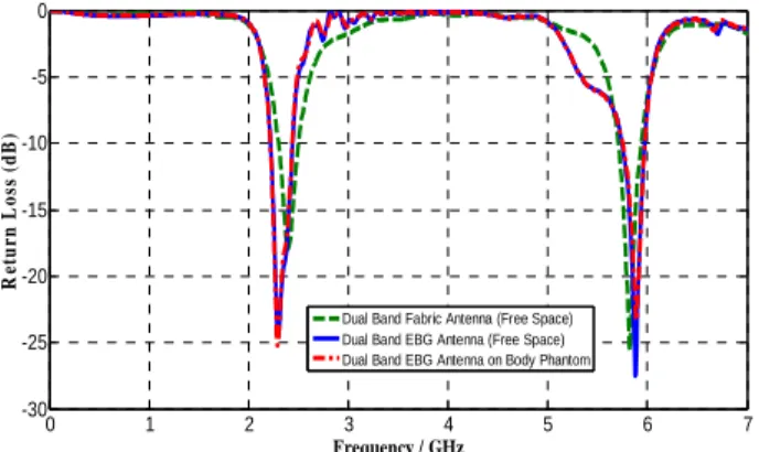
The simulated return loss is shown in Figure 18 along with that of isolated antenna.
0 1 2 3 4 5 6 7
-30 -25 -20 -15 -10 -5 0
Frequency / GHz
R
et
u
rn
L
o
ss
(
d
B
)
Dual Band Fabric Antenna (Free Space) Dual Band EBG Antenna (Free Space) Dual Band EBG Antenna on Body Phantom
Figure 18. Fabric antenna return loss comparison, HIS
Antenna and HIS Antenna over phantom
The HIS antenna has stable response and performed well near body in contrast to antenna without HIS. Resonant
frequencies of the antenna did not change as can be seen in Figure 18. Radiation pattern for HIS antenna is determined for this case and presented in Figure 19.
XZ Plane YZ Plane
(a)
(b)
Figure 19. Radiation patterns of HIS Antenna in free space
and over Phantom (a) f=2.4 GHz (b) f=5.8GHz Slight variation in radiation pattern of HIS antenna in free space and HIS antenna over body phantom is observed. It can be concluded that HIS surface is now acting as isolation layer between body and the antenna that consequently resulted in mitigating antenna-body interaction. As a result, stable resonant frequencies and radiation pattern has been achieved. SAR is an important parameter in case of textile antennas as they are designed to function near human body. This section presents SAR values for both cases i.e. antenna with and without HIS operated near body phantom. In first case the antenna without HIS is operated over phantom by placing it at a distance of 9.4mm. Afterwards, antenna with HIS is placed right above the phantom and SAR is calculated at 2.4GHz and 5.8GHz. For both cases, simulated field strength is shown in Figure 20 and Figure 21. The strongest field is located at the centre for antenna without HIS. For the case of HIS antenna placed over phantom, the maximum field moved to the edges of HIS ground plane as shown in Figure 21 and its magnitude is small as compared to previous case.
(b)
Figure 20. Fabric antenna field strength without HIS (a)
2.4GHz (b) 5.8GHz
(a)
(b)
Figure 21. Fabric antenna field strength with HIS (a)
2.4GHz (b) 5.8GHz
Table 3 presents the simulated SAR values at operating frequencies. For antenna without HIS, it is 11.7W/Kg at 2.4GHz and 2.39W/Kg at 5.8GHz. It has been reduced to 0.682W/Kg at 2.4GHz and 0.0698W/Kg at 5.8GHz for HIS antenna i.e. approximately 94-97% reduction at operating frequencies has been observed.
Table 3 Comparison of SAR for 10g Tissue
SAR
Frequency 2.4GHz 5.8GHz
Antenna without
HIS 11.7 W/Kg 2.39 W/Kg
Antenna with HIS 0.682 W/Kg 0.0692 W/Kg Keeping textile antenna in flat condition is difficult as human body is round in nature, therefore textile antenna will come across bending and crumpling. In this respect, the textile antenna is bent for two radii’s (40mm and 70mm) that nearly
approximates human bicep and leg respectively. The textile antenna with bending along X-axis and Y-axis is shown in Figure 22.
Figure 22. Bending of wearable antenna (a) Along X-axis
(b) Along Y-axis
0 1 2 3 4 5 6 7
-30 -25 -20 -15 -10 -5 0
Frequency / GHz
R
et
u
rn
L
o
ss
(
d
B
)
40 mm radii 70 mm radii Flat
(a)
0 1 2 3 4 5 6 7
-30 -25 -20 -15 -10 -5 0
Frequency / GHz
R
et
u
r
n
L
o
ss
(
d
B
)
40 mm radii 70 mm radii Flat
(b)
Figure 23. Textile antenna return loss for bend condition (a)
Along X-axis (b) Along Y-axis
XZ Plane YZ Plane
(a)
(b)
Figure 24. wearable Antenna radiation pattern for bend
along x-axis (a) f = 2.4GHz (b) f = 5.8GHz
XZ Plane YZ Plane
(a)
(b)
Figure 25. Wearable Antenna radiation pattern for bend
along y-axis (a) f=2.4GHz (b) f=5.8GHz
Similarly, the textile antenna is evaluated for crumpling condition as well. Textile antennas come across crumpling especially near joints in body when worn. For this purpose, the antenna is tested for two crumpling cases as presented in Figure 26.
Figure 26. wearable Antenna under Crumpling Condition
Due to crumpling, size of antenna aperture is reduced. For the first case it reduces from 35mm x 40mm to 27mm x 40mm whereas in second case it reduces to 28mm x 40mm as presented in Figure 26. Return loss over frequency for these cases is shown in Figure 27.
0 1 2 3 4 5 6 7
-30 -25 -20 -15 -10 -5 0
Frequency / GHz
R
tu
rn
L
o
ss
(
d
B
)
Case 1 Case 2 Flat
Figure 27. Crumpled wearable antenna return loss
comparison
Slight variation in operating frequencies has been observed for both the cases as can be observed in Figure 27. Because of reduction in size of antenna due to crumpling, operating frequencies shifts to higher band. Figure 28 presents pattern of the antenna for these conditions to evaluate radiation response. There exist slight variations in radiation pattern for both cases which are comparable to that of antenna in flat condition as well.
(a) (b)
Figure 28. Textile antenna pattern after crumpling (a)
7.
Conclusion
This study has proposed a new dual band wearable PIFA designed to operate at 2.4GHz and 5.8GHz. Its performance has been improved with a dual band HIS designed in the same band. The antenna has a gain of 1.84dBi and 4.45dBi at 2.4GHz and 5.8GHz respectively. When the antenna is integrated with HIS, gain improved to 8dBi and 9dBi at 2.4GHz and 5.8GHz respectively.
Then the antenna was placed on human body phantom and its on-body performance was evaluated. It was observed that its performance deteriorated close to human body. Impedance matching and operating bands were strongly dependent on antenna-body spacing. To overcome these problems antenna integrated with HIS was placed over body phantom and its performance was evaluated. It was observed that antenna performance improved due to isolation effect of HIS. SAR values were calculated for antenna with and without HIS. It was observed that SAR reduced to 0.682W/Kg at 2.4GHz and 0.0692W/Kg at 5.8GHz for 10g tissue. These values are well below the acceptable SAR threshold. This is because of the shielding effect of HIS that resulted in relatively low backward radiation from antenna on to body resulting in reduced values of SAR while having improved gain in direction away from body. The wearable antenna was also tested under bending and crumpling conditions. It was observed that antenna performance was not significantly affected for both the scenarios.
Thus it can be concluded that wearable antenna when integrated with HIS minimizes electromagnetic interaction between human body and the antenna. This will result in an improved on-body performance of the antenna. The proposed antenna can be a good candidate for future body centric wireless communication systems.
References
[1] M. el Azhari, A. Toumanari, R. Latif, and N. el Moussaid, "Relay based thermal aware and mobility support routing protocol for wireless body sensor networks," International Journal of Communication Networks and Information Security (IJCNIS), vol. 8, No.3,pp. 64-73, 2016.
[2] S. Rao, N. Llombart, E. Moradi, K. Koski, T. Bjorninen, L. Sydanheimo, et al., "Antenna applications corner: Miniature implantable and wearable on-body antennas: Towards the new era of wireless body-centric systems," IEEE Antennas and Propagation Magazine, vol. 1, pp. 271-291, 2014.
[3] N. Singh, A. K. Singh, and V. K. Singh, "Design and performance of wearable ultrawide band textile antenna for medical applications," Microwave and Optical Technology Letters, vol. 57, pp. 1553-1557, 2015.
[4] M. Klemm and G. Troester, "Textile UWB antennas for wireless body area networks," IEEE Transactions on Antennas and Propagation, , vol. 54, pp. 3192-3197, 2006.
[5] C. Hertleer, A. Tronquo, H. Rogier, L. Vallozzi, and L. Van Langenhove, "Aperture-coupled patch antenna for integration into wearable textile systems," Antennas and Wireless Propagation Letters, IEEE, vol. 6, pp. 392-395, 2007.
[6] A. Tronquo, H. Rogier, C. Hertleer, and L. Van Langenhove, "Robust planar textile antenna for wireless body LANs operating in 2.45 GHz ISM band," Electronics Letters, vol. 42, pp. 142-143, 2006.
[7] A. Salam, A. A. Khan, and M. S. Hussain, "Dual band microstrip antenna for wearable applications,"Microwave and Optical Technology Letters, vol. 56, pp. 916-918, 2014. [8] S. Agneessens, S. Lemey, T. Vervust, and H. Rogier,
"Wearable, small, and robust: The circular quarter-mode textile antenna," IEEE Antennas and Wireless Propagation Letters, vol. 14, pp. 1482-1485, 2015.
[9] E. F. Sundarsingh, S. Velan, M. Kanagasabai, A. K. Sarma, C. Raviteja, and M. G. N. Alsath, ll"Polygon-shaped slotted dual-band antenna for wearable applications," IEEE Antennas and Wireless Propagation Letters, vol. 13, pp. 611-614, 2014. [10] P. J. Soh, G. Vandenbosch, F. H. Wee, A. van den Bosch, M.
Martinez-Vazquez, and D. Schreurs, "Specific absorption rate (SAR) evaluation of textile antennas," IEEE Antennas and Propagation Magazine, vol. 57, pp. 229-240, 2015.
[11] Z. H. Jiang, D. E. Brocker, P. E. Sieber, and D. H. Werner, "A compact, low-profile metasurface-enabled antenna for wearable medical body-area network devices," IEEE Transactions on Antennas and Propagation, vol. 62, pp. 4021-4030, 2014.
[12] S. Yan, P. J. Soh, and G. A. Vandenbosch, "Compact all-textile dual-band antenna loaded with metamaterial-inspired structure," IEEE Antennas and Wireless Propagation Letters, vol. 14, pp. 1486-1489, 2015.
[13] S. Yan, P. J. Soh, and G. A. Vandenbosch, "Low-profile dual-band textile antenna with artificial magnetic conductor plane," IEEE Transactions on Antennas and Propagation, vol. 62, pp. 6487-6490, 2014.
[14] H.-L. Yang, W. Yao, Y. Yi, X. Huang, S. Wu, and B. Xiao, "A Dual-Band Low-Profile Metasurface-Enabled Wearable Antenna for WLAN Devices," Progress In Electromagnetics Research C, vol. 61, pp. 115-125, 2016.
[15] S. Zhu and R. Langley, "Dual-band wearable textile antenna on an EBG substrate," IEEE Transactions on Antennas and Propagation, vol. 57, pp. 926-935, 2009.
[16] P. Salonen, F. Yang, Y. Rahmat-Samii, and M. Kivikoski, "WEBGA-wearable electromagnetic band-gap antenna," Antennas and Propagation Society International Symposium, 2004. IEEE, pp. 451-454,2004.
[17] S. Bashir, M. Hosseini, R. M. Edwards, M. I. Khattak, and L. Ma, "Bicep mounted low profile wearable antenna based on a non-uniform EBG ground plane-flexible EBG inverted-l (FEBGIL) antenna," Antennas and Propagation Conference, 2008. LAPC 2008. Loughborough, pp. 333-336, 2008. [18] Q. Bai and R. Langley, "Crumpling of PIFA textile antenna,"
IEEE Transactions on Antennas and Propagation, vol. 60, pp. 63-70, 2012.
[19] M. A. R. Osman, M. K. Abd Rahim, N. A. Samsuri, H. A. M. Salim, and M. F. Ali, "Embroidered fully textile wearable antenna for medical monitoring applications," Progress In Electromagnetics Research, vol. 117, pp. 321-337, 2011. [20] S. Rao, N. Llombart, E. Moradi, K. Koski, T. Bjorninen, L.
Sydanheimo, et al., "Miniature implantable and wearable on-body antennas: towards the new era of wireless on-body-centric systems [antenna applications corner]," IEEE Antennas and Propagation Magazine, vol. 56, pp. 271-291, 2014.
[21] P. S. Hall et al., “Antennas and propagation for on-body communication systems,” IEEE Antennas and Propation Magazine, vol. 49, no. 3, pp. 41–58, Jun. 2007.
[22] W. El Hajj, C. Person, and J. Wiart, “A novel investigation of a broadband integrated inverted-F antenna design; application for wearable antenna,” IEEE Transactions on Antennas and Propagation., vol. 62, no. 7, pp. 3843–3846, Jul. 2014. [23] A. Alomainy, Y. Hao, and F. Pasveer, “Numerical and
experimental evaluation of a compact sensor antenna for healthcare devices,” IEEE Transactions on Biomedical Circuits Systems, vol. 1, no. 4, pp. 242–249, Apr. 2007. [24] M. N. Suma, P. C. Bybi, and P. Mohanan, “A wideband
Microwave and Optical Technology Letters., vol. 48, no. 5, pp. 871–873, May 2006.
[25] Z. Wang, L. Z. Lee, D. Psychoudakis, and J. L. Volakis, “Embroidered multiband body-worn antenna for GSM/PCS/WLAN communications,” IEEE Transactions an Antennas and Propagation, vol. 62, no. 6, pp. 3321–3329, Jun. 2014.
[26] P. J. Soh, G. A. E. Vandenbosch, S. L. Ooi, and N. H. M. Rais, “Design of a broadband all-textile slotted PIFA,” IEEE Transactions on Antennas and Propagation., vol. 60, no. 1, pp. 379–384, Jan. 2012.
[27] A. Alomainy, Y. Hao, A. Owadally, C. G. Parnini, Y. Nechayev, C. C. Constantinou, and P. S. Hall, “Statistical analysis and performance evaluation for on-body radio propagation with microstrip patch antennas,” IEEE Transactions on Antennas and Propagation, vol. 55, no. 1, pp. 245–248, Jan. 2007.
[28] N. Haga, K. Saito, M. Takahashi, and K. Ito, “Characteristics of cavity slot antenna for body-area networks,” IEEE Transactions on Antennas and Propagation, vol. 57, no. 4, pp. 837–843, Apr. 2009.
[29] S. Agneessens and H. Rogier, “Compact half diamond dual-band textile HMSIW on-body antenna,” IEEE Transactions on Antennas and Propagation, vol. 62, no. 5, pp. 2374–2381, May 2014.
[30] Geng, J.-P., J. Li, R.-H. Jin, S. Ye, X. Liang, and M. Li, “The development of curved microstrip antenna with defected ground structure,” Progress In Electromagnetics Research, Vol. 98, 53–73, 2009.
[31] D. Sievenpiper, L. Zhang, R. F. Broas, N. G. Alexopolous,and E. Yablonovitch, "High-impedance electromagnetic surfaces with a forbidden frequency band," IEEE Transactions on Microwave Theory and Techniques, vol. 47, pp. 2059-2074, 1999.
[32] E. Rajo-Iglesias, O. Quevedo-Teruel, and L. Inclan-Sanchez, "Mutual coupling reduction in patch antenna arrays by using a planar EBG structure and a multilayer dielectric substrate," IEEE Transactions on Antennas and Propagation, vol. 56, pp. 1648-1655, 2008.
[33] S. D. Assimonis, T. V. Yioultsis, and C. S. Antonopoulos, "Computational investigation and design of planar EBG structures for coupling reduction in antenna applications," IEEE Transactions on Magnetics, vol. 48, pp. 771-774, 2012. [34] Q.-R. Zheng, Y.-Q. Fu, and N.-C. Yuan, "A novel compact
spiral electromagnetic band-gap (EBG) structure," IEEE Transactions on Antennas and Propagation, vol. 56, pp. 1656-1660, 2008.
[35] F. Caminita, S. Costanzo, G. Di Massa, G. Guarnieri, S. Maci, G. Mauriello, et al., "Reduction of patch antenna coupling by using a compact EBG formed by shorted strips with interlocked branch-stubs," IEEE Antennas and Wireless Propagation Letters, vol. 8, pp. 811-814, 2009.
[36] Z. Duan, D. Linton, W. Scanlon, and G. Conway, "Improving wearable slot antenna performance with EBG structures," in Antennas and Propagation Conference, 2008. LAPC 2008. Loughborough, pp. 173-176, 2008.