2018 International Conference on Computational, Modeling, Simulation and Mathematical Statistics (CMSMS 2018) ISBN: 978-1-60595-562-9
Design of LED Collimating Light Source Based on
Simulation Surface Model
Wei SHAO
1, Kai-bin LIU
1, A-wei ZHOU
2,*and Peng PENG
11Department of Precision Instrument, Xi’an University of Technology, Xi’an, Shanxi Province, China
2Department of Mechanical and Electronic Engineering, Xi’an Polytechnic University, Xi’an, Shanxi Province, China
*Corresponding author
Keywords: Optical design, surface model, collimating light source, LED.
Abstract. According to the principle of geometrical optics, a LED collimating light source based on surface model is designed. First, establish a collimator lens mathematical model, then the single light-emitting diode model and the light model were imported into Tracepro software for simulation verification. At last the influence of the size of light-emitting diode on the half - intensity angle and the luminous efficiency were analyzed. The results show that the collimating lens control the half-intensity angle of the light-emitting diode source under 3 degrees. The luminous efficiency of the collimating lens is about 90.6% under consideration of material absorption and other losses.
Introduction
Light-emitting diode possesses such excellent performance as low driving voltage, high photo-electricity efficiency, small volume, fast response, long life, wide color gamut, and mercury-free pollution, and so on[1-3]. As a kind of energy saving and environmental friendly green energy, light-emitting diode is gradually replacing the traditional light source, becoming a new generation of mainstream light source[4]. At present, the application of light-emitting diode in lighting field has developed greatly, such as traffic signal lamp, billboard light source, street lamp, automobile lamp and projector [5]. However, the light-emitting diode light source spatial light intensity distribution is similar to the Lambertian distribution. Its light intensity was cosine distribution with the divergence angle. The illumination in the illuminated surface rapidly decay with the exit angle increases which results in a large energy losses. It is difficult to meet the needs of a variety of lighting scenes [6-7]. Therefore, it is necessary to carry out secondary optical design. The so-called secondary optical design is to change the direction of output light rays to achieve control of the optical path. The freeform surface can control the luminous angle, the optical path difference and other physical quantities because of its high flexibility and freedom. At the same time, it can simplify the optical system. So the current mainstream design is through the construction of freeform surface lens for light-emitting diode secondary optical design [8]. In the secondary optical design, light-emitting diode collimating lens design has been widely used in searchlights, spotlights, flashlights, night vision systems, projection systems and so on.
Algorithm Principle
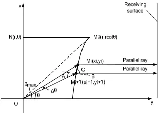
[image:2.612.233.390.144.251.2]The freeform collimating lens designed in this paper is composed of two parts. One is the transmission surface, the other is the total reflection surface. The transmission surface collimates the small angle light rays and the total reflection surface collimates the large angle light rays. Figure 1 is a schematic diagram of a collimating lens of the freeform surface,
Figure. 1. The algorithm diagram of collimating lens.
Wherein the curve 1 is a generatrix of the transmission surface, and the curve 2 is a generatrix of the total reflection surface. In order to allow the light rays emitted by the light-emitting diode light source to be completely reflected by the transmission surface and the total reflection surface. Assuming that the transmission surface and the total reflection surface have a common boundary angleθmax. As long as the coordinates of points on curve 1 and curve 2 are calculated, the generatrixs of transmission surface and total reflection surface can be plotted by using Matlab software based on the iterative relation of the points on the two curves. Importing the two generatrixs into Solidworks software, then add a straight line and rotate 360 degrees along the center axis to get the collimating lens stereoscopic model.
Transmission Generatrix Coordinates Calculation
The transmission generatrix algorithm is shown in Figure 2. Establishing the rectangular coordinate system, assuming that the central axis of the collimating lens is y axis, the radial is x axis, and the light source is at the coordinate origin. In the algorithm, taking the radial radius r, the refractive index of the material n, and the dividing angle θmax of the three parameters as known parameters. And then deriving the relationship between y and x on the transmission generatrix.
Figure 2. The derivation of the generatrix of curve 1.
Firstly, assuming that the slope of the straight line of the light ray at which the Mi+1(xi+1, yi+1) point is k1. Obtaining (1) from the coordinates of the map.
1 cot
k (1)
Its ray equation of loMi+1 is (2).
1
[image:2.612.221.383.495.608.2]Assuming that the slope of the straight line of the light ray at which the Mi (xi, yi) point is k2, its ray equation of loMi is (3).
2 i i
y k x x y (3)
The slope of the tangent line at point Mi (xi, yi) is (4), because the sum of B and C is 90 degrees.
2
k cotC tanB (4)
Obtaining (5) from the law of refraction.
sinAnsinB (5) Obtaining (6) by solving (5).
A arcsin nsinB (6)
Assuming that the slope of the normal line of the light ray at which the Mi (xi, yi) point is k3.
Equation (7) can be obtained from the relationship between k3 and k2.
3 1/ 2
k k (7) A is the angle between the line loMi+1 and the point Mi (xi, yi) normal. Equation (8) can be obtained from the angle formula of the two lines.
1
1 3 2
1 1 3 2 1 1 cot tan tan cot
1 1 1
tan k
k k k B
A k A k k C k (8) Obtaining (9) by substituting (1), (4), (6), and (7) to (8).
2
1 1
2 2 2 2
1 1
1 1
n k k
k
n k k
(9) When ∆θ is enough small, it can be approximated that the neighbor Mi+1(xi+1,yi+1) of Mi (xi , yi) is also on the tangent of the point Mi (xi , yi). Making M0 (r, rcotθmax) as the initial value of (x0,y0) .Putting it into the (3).Solving the simultaneous equation (2) and (3) to get the coordinates of Mi (xi, yi). The general recurrence equation (10) of point (xi,yi) and point (xi+1,yi+1) can be obtained by decreasingθmax by ∆θevery time . i is from 0 toθmax/∆θ, the interval is 1. Each reduction of a ∆θ
can obtain the coordinates of a point M on the generatrix. There areθmax/∆θ discrete points on the
transmission generatrix can be obtained in total.
2 1
1 2
1 1 1
1 max
2
1 1
2 2 2 2
1 1 0 0 max cot 1 1 cot
i i i
i
i i
i i i
i
i i
i
i i
y k x x
k k
y k x
k i
n k k
k
n k k
x r y r
(10)
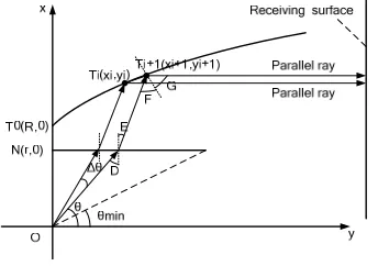
Total Reflection Generatrix Coordinates Calculation
algorithm, taking the radial radius r, the refractive index of the material n, the radial radius R of total reflection, and the dividing angle θmin which is equivalent to a transmission algorithm θmaxof the four parameters as known parameters. And then deriving the relationship between y and x on the transmission generatrix.
Figure 3. The derivation of the generatrix of curve 2.
Firstly, assuming that the slope of the straight line of the light ray at which the Ti (xi, yi) point is k4. Obtaining (11) from the coordinates of the map.
4 tan
k G (11)
The slope of the tangent line at point Ti (xi, yi) is (12), because the sum of 90 degrees minus E and twice the G is 180 degrees.
4
90 tan
2 E
k
(12) Obtaining (13) from the law of refraction.
sin sin cos
n E D (13) Obtaining (14) by solving (13).
cos
arcsin( )
E
n
(14) Obtaining (15) by substituting (14) into (12).
4
cos
90 arcsin( )
tan
2 n k
(15) Obtaining (16) of the tangent equation for Ti (xi, yi).
cos
90 arcsin
tan ( )
2 i i
n
y x x y
(16) When ∆θ is enough small, it can be approximated that the neighbor Ti+1(xi+1,yi+1)of Ti(xi ,yi)is also on the tangent of the point Ti(xi ,yi). The ray equation (17) of point Ti+1(xi+1, yi+1) can be obtained by coordinate map.
tan cot
y E x r r (17) Taking T0(x0, y0) as the initial value of (x0, y0) into (17). Solving the simultaneous equation (16)
(18) of point (xi , yi) and point (xi+1 , yi+1) can be obtained. i is from 0 to (90-θmax)/∆θ, the interval is 1. Each reduction of a ∆θ can obtain the coordinates of a point T on the generatrix. There are (90-θmax)/∆θdiscrete points on the transmission generatrix can be obtained in total.
1 1 1 0 0 cot tan tan tan cot cos arcsin cos 90 arcsin tan 2 90 0i i i i i
i
i i
i i i i
i i
i
i
i
k x y r E
x
k E
y E x r r
E n n k i x R y
(18)
Modeling and Simulation Results of Collimating Lens
For the convenience of processing, the material of the lens is set to BK7 glass, so the refractive index n in (10) and (18) is 1.51872. The selection of the initial point is related to the size of the optical element. In this paper, the radial radius r of the transmission surface is 0.003m, the radial radius R of the total reflection surface is 0.004m, the boundary angleθmin is 25 degrees, the interval ∆θis 0.1 degree.
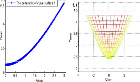
Firstly, the iteration method is used to program the coordinates of the points on the transmission generatrix and the total reflection generatrix in Matlab software. The two generatrix equation are obtained by fitting the discrete data points, and both of the generatrix are rotated around the central axis to obtain the three-dimensional surface. Figure 4 (a) is a transmission curved surface generatrix and its 3D modeling curved surface (b). Figure 5 (a) is a total reflection curved surface generatrix and its 3D modeling surface (b).
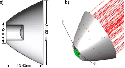
[image:5.612.190.415.543.676.2]Importing the two generatrixs into Solidworks software, then adding a straight line and rotating 360 ° along the center axis to get the collimating lens stereoscopic model. The solid model of the collimating lens is shown in Figure 6 (a). The diameter is 24.82mm, the thickness is 13.43mm.
Figure 5. The generatrix of curve surface 2 (a) and 3D modeling surface (b).
Finally, the collimating lens model is imported into Tracepro software, and the light-emitting diode light source is used for collimation simulation in Tracepro software. In the practical application of light-emitting diode, it can be seen as an approximate Lambertian light source [13]. In this paper, a single light-emitting diode light source of OSRAM model LCW CR7P.CC is used to simulate and verify the collimating lens. Light-emitting diode entity model and ray model are imported into Tracepro software. According to the algorithm, the light-emitting diode should be placed at the center origin.
In order to make the optical simulation accord with the actual situation, the reflectivity of the total reflection surface is set to 96% and the absorption rate is set to 4% in the Tracepro software. At the same time, the transmittance of the transmission surface is set to 96%, and the absorption rate is set to 4%. In order to receive the light rays through the energy distribution of the collimating lens, a detector panel is provided in the direction of the optical axis, and the receiving surface is set as the ideal absorbing surface. It can be seen from Figure 6 (b), light-emitting diode through the collimating lens of the secondary light distribution. The rays are nearly parallel out. Collimating lens, and the back light rays' half-intensity angle is approximately 3 degrees.
In the algorithm above, the light-emitting diode is assumed to be the point source of the coordinate origin. In fact, the emitting diode will have a certain size, and the size of the light-emitting diode will have some influence on the optical performance of the collimating lens. In the simulation, light-emitting diode is set as a square surface light source, and the light distribution curve is a Lambertian light distribution mode, and the size of the square side is used to represent the size of the light-emitting diode. The effect of light-emitting diode size on light efficiency and half-intensity light angle is discussed.
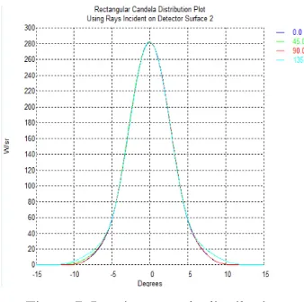
[image:6.612.208.412.517.629.2]Figure 7. Luminous angle distribution.
[image:7.612.224.389.358.492.2]Figure 8 shows the relationship between the light-emitting diode size and the half-intensity angle. When the length of the light-emitting diode is increased from 0.1mm to 1.1mm, the divergence angle increases, but the growth is slow and half-intensity angle within 2.6 degrees. With the size of light-emitting diode continues to increase, the half-intensity angle increases rapidly. When the size of the light-emitting diode is increased to 1.9mm, the half intensity angle increases to 4.4 degrees. In summary, with the increase of the size of the light-emitting diode, the collimation of the collimating lens decreases.
[image:7.612.205.408.537.663.2]Figure 8. The relationship between the size of light-emitting diode and half-intensity light angle. Table 1. The relation between light-emitting diode size and performance of collimating lens.
Table Column Head
Size(mm) Efficiency (%) Half-intensity angle (°)
0.1 92.17 1.6
0.3 92.17 1.8
0.7 92.16 2.3
1.1 92.10 2.8
1.5 91.54 3.5
1.9 89.31 4.4
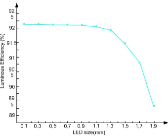
Figure 9. The relationship between the size of light-emitting diode and luminous efficiency.
Conclusion
In this paper, a LED collimating light source based on freeform surface collimating lens is designed based on geometrical optics principle, and a detailed algorithm for constructing collimating lens model is given. Ray tracing of collimating lens is carried out by using Tracepro software. The optical simulation results show that the collimator lens controls the half- intensity angle of the light-emitting diode in the range of 3 degrees. The transmission efficiency of the collimating lens is about 95.64% without considering the material absorption and other losses. The transmission efficiency of the collimating lens is about 90.6% under the condition of considering material absorption and other losses. The influence of light-emitting diode size on half-intensity angle and light efficiency was analyzed. The simulation results show that with the increase of the size of light-emitting diode, the half-intensity angle becomes larger and larger, the collimation of collimating lens is getting worse and worse, and the utilization ratio of light energy is getting lower and lower. The LED collimating light source can be used in lighting systems, such as precision optoelectronic detection lighting and projection systems.
Acknowledgment
This project is supported by National Natural Science Foundation of China (Grant No. 51505359, 51775433)
References
[1] Zhao Huan, Li Chang Gen, Chen Zhitao, et al. Design of Cllimating Lens with Uniform Illumination for LED Based on Double Feeform Surface [J]. Acta Optica Sinica, 2017, 37 (4): 264-269.
[2] Zhao Huifu, Liu Hua, Sun Qiang, et al. Design of RIXR LED collimatine system [J].Optics and Precision Engineering, 2011,
[3] 19(7): 1472-1479.
[4] Zeng Chiliang, Liao Wenzhe. Secondary Optical Lens Design for LED to Achieve Angular Deflection [J]. Laser & Optoelectronics Progress, 2017, 54 (2): 022204.
[5] Yu Guiying, Jin Ji, Ni Xiaowu, Zheng Yingjun. Design for LED Uniform Illumination Reflector Based on Etendue [J]. Acta Optica Sinica, 2009, 29(8): 2297-2301.
[7] Ding Yi, Liu Xu, Zheng Zhenrong, Gu Peifu. Freeform LED lens for uniform illumination [J]. Optics Express, 2008, 16(17): 12958-12966.
[8] Liang Wenyue, Li Yuanxing, Long Yongbing, et al. Design of Freeform Surface Lens with Chip on Board LED Sources for Uniform Illumination [J]. Laser & Optoelectronics Progress, 2017, 54(1): 012202.
[9] Zhou Zhen, Su Chengyue, Fu Qian, Zhang Chunhua. LED collimating lens based on free-form surface [J]. Journal of Applied Optics, 2012, 33 (6): 1058-1062.
[10] Li Cheng, Li Nong. A LED Lens Design Method for Uniform Illumination [J]. China Illumination Engineering Journal, 2010, 21(3): 46-49.
[11] Zhang Hang, Liang Xue, Yan Jinhua, et al. Compound Parabolic Concentrator-Simultaneors Multiple Surfaces Design Methods for LED Collimators [J]. Acta Optica Sinica, 2012, 32(9): 922004.
[12] Liu Yanjie. Design and Simulation of DLP Projection Lighting System Based on LED Light Source [D]. Shenzhen: Shenzhen University, 2015: 38-46.
[13] Wu Rengmao, Tu Dawei, Huang Zhihua. Design of uniform illumination projector with high power LED [J]. Journal of Applied Optics, 2009, 30(3): 372-376.