2019 International Conference on Information Technology, Electrical and Electronic Engineering (ITEEE 2019) ISBN: 978-1-60595-606-0
A Novel Quasi-elliptic Bandpass Filter Using Half-mode Substrate
Integrated Waveguide Cavities
Da-long LV*, Qing LIU, Xian WANG and Dong-fang ZHOU
National Digital Switching System Engineering &Technological Research Center, Zhengzhou, Henan 450001, China
*Corresponding author
Keywords: Bandpass filter (BPF), Quasi-elliptic, Cross-coupled, Half-mode substrate integrated waveguide (HMSIW), Spurious resonance.
Abstract. A fourth-order cross-coupled bandpass filter (BPF) using three half-mode substrate integrated waveguide (HMSIW) cavities and a spurious resonance is proposed. The HMSIW cavity is derived from diamond-shaped SIW; a new spurious resonance mode is built by adding post-wall irises between the two coupled HMSIW cavities and the resonance of spurious mode is analyzed. From the demonstration, an X-band cross-coupled quasi-elliptic filter is designed, simulated, and fabricated. The measured results are in good agreement with simulated results.
Introduction
Modern communication systems require microwave filter with compact size and high performance. Design of quasi-elliptic filters with finite transmission zeros using cross-coupled approach is a well-established technique to achieve high-selectivity and reduce size [1-2]. Cross coupled filters using waveguide are widely used in various microwave and millimeter-wave communication systems due to their high-selectivity, high Q value and high-power capability [3].
In [4], two cross-coupled bandpass filters with source-load coupling had been designed using a planar negative coupling scheme including a magnetic coupling post-wall iris and a balanced microstrip line with a pair of metallic via-holes. In [5], a type of quasi-elliptic filter with controllable electric and magnetic mixed coupling based on SIW resonators using two-layer printed circuit board process had been designed. In [6], A HMSIW BPF with a single transmission zero (TZ) near the upper passband using cross-coupling was designed to reduce size. But the selectivity is not very good.
In this paper, a fourth-order X-band cross-coupled BPF using three half mode diamond shaped SIW cavities and a spurious resonance mode is designed. The designed cross-coupled filter with two TZs near lower and upper passband to achieve high selectivity and using the HMSIW cavities can reduce
half of the size compared with using intact TE101 mode cavities. Besides, the spurious resonance
mode is implemented to design the BPF, which can further reduce quarter of the circuit size.
Analysis Of The Proposed Cross-Coupled Filter
The geometric configuration of the proposed quasi-elliptic BPF using SIW cavities and its corresponding equivalent topology is shown in Figs. 1(a) and (b), respectively. Except that the main couplings between R1 and R2, and between R2 and R3 are magnetic couplings, all the other couplings between two resonances modes are electric coupling.
between R4 and R3 are electric coupling, and the reason is explained in part B. Moreover, the frequency of spurious resonance can be tuned to approach the resonance frequencies of HMSIW cavities by changing the size and position of coupling post-wall iris.
、
(a) (b)
Figure 1. (a) Geometric configuration of the proposed cross-coupled SIW filter (b) its corresponding equivalent topology of the proposed BPF.
The HMSIW Cavity
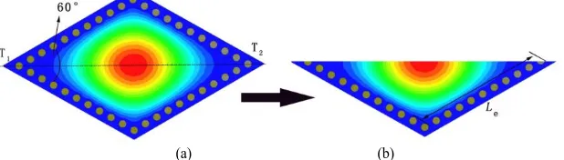
The presented HMSIW cavity is derived from diamond shaped SIW with a 60° of an acute angle, as shown in Fig. 2. The electric field distribution for the fundamental mode of the diamond shaped SIW
cavity is shown in Fig. 2(a); the electric field is at the vertical center plane, and it is about T1T2 plane
of symmetry, so the center plane (T1T2) can be considered as an equivalent magnetic wall. Thus, the
half mode diamond shaped SIW can be obtained, as shown in Fig. 2(b). The presented HMSIW is
employed to design resonators 1, 2 and 3. The equivalent length Le of half mode diamond SIW cavity
can be obtained by using ANSYS HFSS conveniently.
[image:2.595.125.460.121.249.2](a) (b)
Figure 2. The electric field distribution for the fundamental mode of (a) whole diamond shaped SIW cavity (b) the half mode diamond shaped SIW cavity.
Internal Coupling
Electric and magnetic coupling coefficients are shown in Figs. 3(a) and (b), respectively. The electric coupling coefficient is reduced by increasing Lgap3, and it also can turn to magnetic coupling with large Lgap3. The coupling between R1 and R3 is cross coupling, thus the coupling coefficient of R1 and R3 is less than that of R1 and R2 and that of R2 and R3.
[image:2.595.146.455.420.508.2]The magnetic field of R4 and that of R1, R2, and R3 are almost vertical, thus the magnetic coupling is very weak and can be ignored. As shown in Figs. 4(b) and (d), the overlap region of electric fields of R2 and R4 are almost zero, thus the cross coupled between R2 and R4 can be ignored for its weakness. As shown in Figs. 4(a) and (d), or in Figs. 4(c) and (d), the overlap region of electric fields of R1 and R4 or that of R3 and R4 is not zero, thus the coupling between R1 and R4 and between R3 and R4 are electric coupling. Thus, as shown in Fig. 1(b), the topological structure can achieve a TZ near lower passband because the main and cross couplings between R1, R3 and R4 are all electric coupling. Thus, the two TZs at near lower and upper passband of the proposed filter can enhance skirt selectivity.
0.5 1.0 1.5 2.0 2.5 3.0 3.5 4.0 0.02 0.03 0.04 0.05 0.06 0.07 0.08 0.09 co u p lin g c o e ff ic ie n t
Lgap3 (mm) 1.5 2.0 2.5 3.0 3.5 4.0 4.5 5.0 5.5
0.00 0.02 0.04 0.06 0.08 0.10 0.12 0.14 0.16 co u p lin g c o e ff ic ie n t
Lgap1 (mm)
[image:3.595.101.499.200.347.2](a) (b)
Figure 3. Coupling coefficient of (a) the electric coupling structure (b) the magnetic coupling structure.
(a) (b)
[image:3.595.171.411.378.498.2](c) (d)
Figure 4. Electronic fields of the R1, R2, R3, and R3 resonant modes (denoted modes 1, 2, 3, and 4, respectively) in the proposed structure with cross coupling; and resonance frequencies are f1, f2, f3, and f4, respectively; and f2< f1< f3< f4,
(a) mode 1(b) mode 2 (c) mode 3 (c) mode 4.
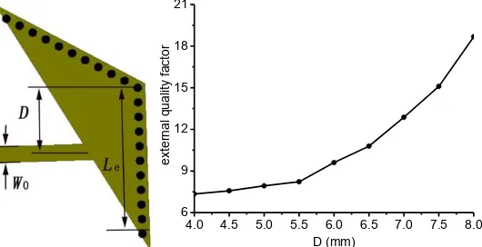
4.0 4.5 5.0 5.5 6.0 6.5 7.0 7.5 8.0
6 9 12 15 18 21 e xte rn a l q u a lity f a cto r
D (mm)
Figure 5. External quality factor (Qe) of the input/output structure.
External Coupling
[image:3.595.167.432.546.682.2]Tune the Spurious Resonance Frequency
The electric field distribution for the spurious resonance mode is shown in Fig. 4(d). The frequency is mainly affected by the size and position of magnetic coupling post-wall iris and also affected by the size of R2 when Lgap1 being large. Actually, the spurious resonance mode is the first higher order mode of the half mode diamond shaped SIW cavity when Lgap1 is small. The electric field distribution is changed by changing the boundary conditions for different size and position of magnetic coupling post-wall iris. Thus, the spurious resonance frequency can be tuned by parameters Lgap1 and Dgap1.
Under the condition of weak coupling between R1 and source, and between R3 and load, the resonance frequencies of R1, R2, R3 and R4, can be extracted by ANASYS HFSS. As shown in Fig. 6, the spurious resonance frequency can be shifted to the resonance frequencies of R1, R2 and R3. Thus, the spurious resonance mode can be combined with three fundamental modes of HMSIW cavities to design cross-coupled filter. Compared with using four HMSIW cavities to design the fourth-order quasi-elliptic filter, using the spurious resonance to design the fourth-order filter can reduce quarter the circuit size.
4.5 5.0 5.5 6.0 6.5 7.0 7.5 8.0 0.8
1.0 1.2
fr
e
q
u
e
n
cy
(G
H
z)
Lgap1 (mm) f1 f2 f3 f4 1.4
1.5 2.0 2.5 3.0 3.5 4.0 4.5 0.8
1.0 1.2
fr
e
q
u
e
n
cy
(G
H
z)
Dgap1 (mm) f1 f2 f3 f4 1.4
[image:4.595.99.472.295.444.2](a) (b)
Figure 6. Resonance frequencies of R1, R2, R3 and R4, denoted f1, f2, f3 and f4, respectively (a) against parameter Lgap1 (b) against parameter Dgap1.
6 7 8 9 10 11 12 13 -40
-30 -20 -10 0
S
-p
a
ra
m
e
te
r (
d
B
)
frequency (GHz)
S21, mea. S11, mea.
[image:4.595.114.304.482.642.2]S21, sim. S11, sim.
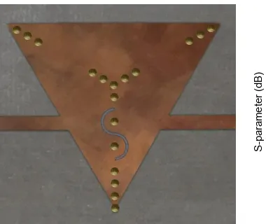
Figure 7. Photograph of fabricated filter. Figure 8. Simulated and measured results.
Experiments and Result
[image:4.595.166.478.487.640.2]As shown in Fig. 8, the measured 3dB fractional bandwidth is 27.8% at the measured center frequency f0=9.99GHz. The measured in-band return loss is below -15dB, while the measured minimum in-band insertion loss is approximately 1.37dB. Moreover, two transmission zeros near the lower and upper passband are observed at 7.4GHz and 12.06GHz, respectively. The measured results are in good agreement with the simulated ones. The designed filter shares a compact size for using half mode SIW cavities and spurious resonance. Compared with cross-coupled filters using the intact TE101 mode based on SIW cavity, it reduces 62.5% of the size.
Conclusion
A planar X-band fourth-order cross-coupling bandpass filter with a quasi-elliptic response using SIW technology was studied in detail. The designed filter is implemented by using three HMSIW cavities and a spurious resonance mode. And it shares the advantages of good selectivity, compact size and flat group delay. Good agreements have been observed between the simulated and the measured results.
References
[1]DL Diedhiou, E Rius, JF Favennec, A El Mostrah. "Ku-Band Cross-Coupled Ceramic SIW Filter
Using a Novel Electric Cross-Coupling." IEEE Microwave & Wireless Components Letters 25.2(2015):109-111.
[2]Esmaeili M., and J. Bornemann. "Quasi-Elliptic Triple-Stopband Filter Based On Six
Cross-Coupled SIW Resonators." IEEE Microwave & Wireless Components Letters
25.12(2015):802-804.
[3]Amari S., and U. Rosenberg. "Characteristics of cross (bypass) coupling through higher/lower
order modes and their applications in elliptic filter design." IEEE Transactions on Microwave Theory & Techniques Mtt53.10(2005):3135-3141.
[4]Chen Xiao Ping, and K. Wu. "Substrate Integrated Waveguide Cross-Coupled Filter With
Negative Coupling Structure." IEEE Transactions on Microwave Theory & Techniques 56.1(2008):142-149.
[5]K Gong, W Hong, Y Zhang, P Chen, CJ You. "Substrate Integrated Waveguide Quasi-Elliptic
Filters With Controllable Electric and Magnetic Mixed Coupling." IEEE Transactions on Microwave Theory & Techniques 60.10(2012):3071-3078.
[6]Hong, Pang, and H. Jin. "Half mode substrate integrated waveguide (HMSIW) bandpass filter
using Cross-Coupling." Computational Problem-Solving (ICCP), 2010 International Conference on IEEE, 2010:196-198.
[7]Chang, Chi Yang, and W. C. Hsu. "Novel planar, square-shaped, dielectric-waveguide, single-,
and dual-mode filters." IEEE Transactions on Microwave Theory & Techniques