A High Spectral Efficient Non-Binary TTCM-Assisted G2
STBC-OFDM for 4G Systems
Raad H. Thaher
College of Engineering Al-Mustansiriyah UniversityABSTRACT
This paper deals with the MIMO-OFDM technique that candidate with the fourth generation (4G) of the wireless communication systems, this technique can provide high data rate transmission without increasing transmit power and expanding bandwidth, also it can efficiently use space resources and has a bright future. This paper presents the channel coding assisted STBC-OFDM systems, and employs the Coded Modulation techniques (CM), since the signal bandwidth available for wireless communications is limited. Furthermore, a non-binary Turbo Trellis Coded Modulation (TTCM) decoder-based multidimensional MAP algorithm-assisted G2 STBC-OFDM is design and implemented. The idea of Non-binary codes has been extended for symbols defined over rings of integers, which outperform binary codes with only a small increase in decoding complexity. The simulation results show that the performance of the TTCM decoding algorithm outperforms the binary decoding methods and suitable to deal with error control coding of the STBC-OFDM schemes.
Keywords
Turbo codes, TTCM, non-binary error correcting codes, Rings of integers, MIMO, OFDM MIMO-OFDM, STBC, 4G..
1.
INTRODUCTION
Increasing market expectations for 3G (third generation) systems show a great demand for a wider range of services spanning from voice to high-rate data services required for supporting mobile multimedia communications. On the other hand, the available radio spectrum is limited and the communication capacity needs cannot be met without a significant increase in spectral efficiency.
4G technology is the latest technology after the 3G systems. These 4G Communication systems still solve the remaining problems of 3G systems. 4G is characterized by three words: ubiquitous, mobile, and broadband [1]. The main key features of 4G are receiving a large volume of information, data, pictures, video and so on. A MIMO system is capable of exploiting transmitter and receiver diversity, hence maintaining reliable communications.
As a key building block of next-generation wireless communication systems, MIMOs are capable of supporting significantly higher data rates than the Universal Mobile Telecommunications System (UMTS) and the High-Speed Downlink Packet Access (HSDPA) based 3G networks [2]. To overcome a multipath-fading environment with low complexity and to achieve wireless broadband multimedia communication systems (WBMCS), the orthogonal frequency-division multiplexing (OFDM) transmission
scheme is employed [3]. OFDM is one of the applications of a parallel-data-transmission scheme, which reduces the influence of multipath fading and makes complex equalizers unnecessary.
Advances in coding, such as turbo [4] and low density parity check codes [5], made it feasible to approach the Shannon capacity limit [6] in systems with a single antenna link. Significant further advances in spectral efficiency are available through increasing the number of antennas at both the transmitter and the receiver [7, 8, 9].
Further performance gains can be achieved by using non-binary codes in the coded modulation scheme, but with an increase in the decoding complexity [10].
J. Kumari J, 2011 [11] analyzed the performance of MIMO-OFDM system employing Quadrature Amplitude Modulation (QAM) in Rayleigh fading channel, since the use of multiple antennas at both ends of a wireless link (multiple-input multiple output (MIMO) technology) has recently been demonstrated to have the potential of achieving extraordinary data rates. Orthogonal frequency division multiplexing (OFDM) significantly reduces receiver complexity in wireless broadband systems. The use of MIMO technology in combination with OFDM, i.e., MIMO-OFDM therefore seems to be an attractive solution for future broadband wireless systems.
L. Hanzo et. al., 2011 [12] presented that the CM-assisted STBC schemes were found to improve significantly the system’s achievable performance. Furthermore, the TTCM-STBC concatenated scheme was observed to give the best performance among all the CM-STBC concatenated schemes. Also, the TTCM-assisted G2 coded OFDM scheme gives a better performance than the LDPC-assisted G2 coded OFDM scheme. Furthermore, in the context of the achievable coding gain versus complexity performance, it was found that the TTCM-assisted schemes are capable of achieving higher coding gains in the relatively high-complexity range, than the LDPC-assisted candidate schemes.
2.
OFDM- MIMO, and MIMO-OFDM
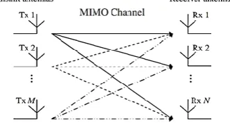
can be considered as time-invariant during one OFDM symbol and that fading per sub-channel can be considered as flat. As conventional methods like using more bandwidth or higher order modulation types are limited, new methods of using the transmission channel have to be used. Multiple antenna systems (Multiple Input, Multiple Output– MIMO) give a significant enhancement to data rate and channel capacity. A MIMO system employs multiple transmitter and receiver antennas for delivering parallel data streams, as illustrated in Figure (1). Since the information is transmitted through different paths, a MIMO system is capable of exploiting transmitter and receiver diversity, hence maintaining reliable communications.
Fig 1: A MIMO System.
As compared with Single-Input, Single-Output (SISO) systems, the most significant advantages of MIMO systems are; a significant increase of both the system’s capacity and spectral efficiency, and dramatic reduction of the effects of fading due to the increased diversity.
The quality of a wireless link can be described by three basic parameters, namely the transmission rate, the transmission range and the transmission reliability. Conventionally, the transmission rate may be increased by reducing the transmission range and reliability. By contrast, the transmission range may be extended at the cost of a lower transmission rate and reliability, while the transmission reliability may be improved by reducing the transmission rate and range [18].
However, with the advent of MIMO-assisted OFDM systems, the above-mentioned three parameters may be simultaneously improved. Initial field tests of broadband wireless MIMO-OFDM communication systems have shown that an increased capacity, coverage and reliability are achievable with the aid of MIMO techniques [19].
A generic MIMO-OFDM system employing K orthogonal frequency-domain subcarriers and having mt and nr transmit and receive antennas, respectively.
Firstly, the OFDM modulation technique is capable of coping with the highly frequency-selective, time-variant channel characteristics associated with mobile wireless communication channels, while possessing a high grade of structural flexibility for exploiting the beneficial properties of MIMO architectures.
The family of space–time signal processing methods, which allow for the efficient implementation of communication systems employing MIMO architectures, is commonly referred to as smart antennas.
The schematic of a typical MIMO-OFDM system’s physical layer is depicted in Figure (2). The transmitter of the MIMO-OFDM system considered is typically constituted by the encoder and modulator, generating a set of mt
complex-valued baseband time-domain signals. The modulated baseband signals are then processed in parallel.
Specifically, they are over sampled and shaped using a Nyquist filter. The resultant over sampled signals are then converted into an analogue pass band signal using a bank of D/A converters and up converted to the RF band.
At the receiver side of the MIMO-OFDM transceiver, the inverse process takes place, where the set of received RF signals associated with the nr receive antenna elements is amplified by the RF amplifier and down converted to an intermediate-frequency passband.
The resultant passband signals are then sampled by a bank of A/D converters, down converted to the baseband, filtered by a matched Nyquist filter and finally decimated, in order to produce a set of discrete complex-valued baseband signals. The resultant set of discrete signals is processed by the corresponding demodulator and decoder module seen in Figure (2) where the transmitted information-carrying symbols are detected.
Fig 2: Schematic of a typical MIMO-OFDM system’s physical layer
The discrete frequency-domain model of the MIMO-OFDM system is illustrated in Figure (2( may be characterized as a generalization of the Single-Input Single-Output (SISO) case:
(1) where n =0, 1,... and k =0,...,K − 1 are the OFDM symbol and subcarrier indices, respectively, while yi[n, k], xj [n, k] and wi[n, k] denote the symbol received at the ith receive antenna, the symbol transmitted from the jth transmit antenna and the Gaussian noise sample encountered at the ith receive antenna, respectively. Furthermore, Hij [n, k] represents the complex-valued CTF coefficient associated with the propagation link connecting the jth transmit and ith receive antennas at the kth OFDM subcarrier and time instance n. The MIMO-OFDM system model described by (2) can be interpreted as the per-OFDM- subcarrier vector expression of
(2)
3.
Alamouti's G2 STBC
[image:2.595.317.550.276.410.2]hence can be regarded as information symbols. Thus, (k × b) input bits are conveyed by each (n × p) block.
The G2 transmission matrix can be derived in the form of [20].
(3) Since there are k = 2 input symbols, namely x1 and x2, the code rate of G2 is R = k/n =1.
Two algorithms are widely used for decoding STBCs. The maximum likelihood (ML) decoding algorithm generates hard-decision outputs, while the Maximum-A-Posteriori (MAP) decoding algorithm is capable of providing soft outputs, which readily lend themselves to channel coding for achieving further performance improvements.
3.1
Maximum-A-Posteriori Decoding
Bauch [21] presented a simple symbol-by-symbol MAP algorithm for decoding STBCs. According to [21], the a posteriori probability of each information symbol xi (i =1,...,k) is given by
(4)
Where (j =1,...,q) represents the received signal vector at receiver j during the period spanning from time slot 1 to time slot n, for the STBC G2 (k = 2, n = 2) the a posteriori probabilities are given by
,) += = , + ( )
(5)
,) += = , + ( )
(6) The corresponding a posteriori probabilities of the bits (i.e. the corresponding soft outputs) using the symbol-to-bit probability conversion of
(7)
Where P(di = 0) or P(di =1) represents the probability of the ith bit, namely di, of the b-bit symbol being zero and one, respectively. Then the relevant soft outputs can be forwarded to the channel decoders, which will make a hard decision to finally decode the received signals.
3.2
Channel-Coded STBC
The MAP algorithm invoked for decoding STBCs can be exploited by concatenated channel decoders for further improving the system’s performance. This paper concatenates on the STBCs with a Turbo Convolutional (TC) code [22, 4]. The STBCs can also be concatenated with a range of other channel codes, such as Convolutional Codes (CCs), Turbo Bose–Chaudhuri–Hocquenghem (TBCH) codes (a class of FEC codes), etc. The best scheme found was the half-rate TC(2,1,4) code in conjunction with the STBC G2. TTCM [23] is a more recent joint coding and modulation scheme which
has a structure similar to that of the family of binary turbo codes,
4.
Non-Binary TTCM
Extending binary turbo codes to non-binary turbo codes can be considered, the principle of the non-binary turbo decoding algorithm remains the same. One of the main differences is the trellis diagram associated with a non-binary convolutional code, which has more branches leaving and entering nodes in the trellis, resulting in more paths and higher decoding complexity.
The non-binary turbo encoder has the same structure as the binary turbo encoder, with the component encoders being replaced by RSC codes defined over a ring of integers , where M is the cardinality of the ring. The non-binary turbo encoder is given in Figure (3). The message symbols xt and the turbo encoder output symbols are now defined over as follows:
∈ {0, 1, 2, . . . M-1} is a turbo encoder output corresponding to an information bit at time t.
∈ {0, 1, 2, . . . M-1} is a parity bit from the first component RSC encoder.
∈ {0, 1, 2, . . . M-1} is a parity bit from the second component RSC encoder.
The upper encoder receives the data directly, while the lower encoder receives the data after it has been interleaved by a permutation function, Π. The interleaver is in general a pseudo random interleaver that is it rearranges bits according to a prescribed but randomly-generated rule. The interleaver operates in a block-wise fashion, interleaving L bits at a time, and thus turbo codes can be viewed as block codes.
Fig3: The non-binary turbo encoder
A -ring-TTCM encoder system is similar to a classical -ring- Turbo encoder (parallel concatenation is evident), but the difference is that, blocks of n coded bits are treated as input symbols, and thus, the interleaver is symbol–oriented, and the component M-ary RSC encoders are trellis encoders– for example, 8–PSK encoder for n = 3, and QAM encoder for n = 4. The final sequence of transmitted symbols is generated by selecting symbols alternately from the two encoders.
4.1
Non-Binary Iterative Turbo Decoding
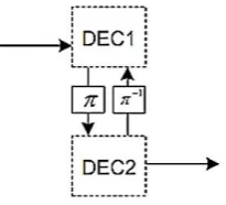
[image:4.595.113.216.70.163.2]
Fig 4: Iterative decoding in MAP algorithm
The design procedure of a -ring-Turbo decoder can be divided into three stages:
The first stage is to derive the reliability values of the systematic information, , the parity bits from encoder 1, , and the interleaved parity bits from encoder 2, .
The second stage is to employ the Maximum A Posteriori (MAP) decoding algorithm to perform the symbol-by-symbol, which defined over a ring of integers , decoding and then decision making.
The third stage is to derive the mathematical relations that achieve connection between decoder 1 and decoder 2 through iteration cycles.
In non-binary systems, expanding to a ring of integers , it must be considered the reliabilities of the other symbols too. The multi-dimensional log-likelihood ratios (multi-dimensional LLRs) for an event u being an element in are:
(8) These multi-dimensional LLRs are used by non-binary turbo decoder as its inputs, and their values depend on the type of the channel and the modulation scheme used.
To derive the multi-dimensional LLRs of a 4-state -ring-Turbo decoder, with M ∈ {0, 1, 2, 3}, and assuming for simplicity, the AWGN channel and 4-ary PAM or 4-ary ASK modulation schemes with constellation points at
are used, where Es, is symbol energy.
Since, the values of the non-binary turbo encoder output symbols are ∈ {0, 1, 2, 3}, and then mapping of to the 4-ary ASK constellation, , i = 0, 1, 2 is given below:
, ,
(9)
Thus, ∈ {-3, -1, 3, -1}, where i = 0, 1, 2 according to the mapping relations of (4.18).
To calculate the reliability of the systematic information bit,
:
(10)
Since, represents the conditional probability density function (PDF) for AWGN channel and is given by
(11)
Where , represents the noise variance, for 4-PAM modulation with constellation points at :
, and
, then
,
Let
(12) Thus, each one of the systematic information bit, , the
parity bit from encoder 1, , and the interleaved parity bit from encoder 2, , has three reliability values, respectively, as shown below in system of equations:
(13)
Where i = 1, 2, 3.
Thus the output of each decoder, in each decision case is defined by the multi-dimensional LLR:
Case 1: the decision between (0&1);
(14) Case 2: the decision between (0&2);
(15) Case 3: the decision between (0&3);
(16)
5.
Proposed Z_M-ring-TTCM
Modulation-assisted STBC-OFDM Scheme
The source information bits are first encoded and modulated by the -ring-TTCM encoder followed by the space–time encoder, the STBC employed was the G2 code, which invokes two transmitter antennas, and the two space–time-coded samples are mapped to two consecutive OFDM subcarriers and OFDM modulated. The OFDM symbols are then transmitted via the multi-path fading channel, and the received noise-contaminated symbols are forwarded to the OFDM demodulator. The recovered signal is then space–time soft decoded and the soft outputs are fed to the - ring-TTCM-decoder which used the multi-dimensional MAP algorithm for recovering the most likely transmitted information bits.
Fig 5: Schematic diagram of the proposed -ring-TTCM-assisted G2 STBC-OFDM system.
6.
Simulation Results
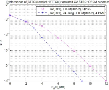
[image:5.595.56.291.216.323.2]The schematic design of -ring-TTCM encoder can be simulated on computer. The -ring-TTCM encoder passes through 4-state transitions, since at each state two sets of non-binary mathematical operations are used to encode a message, one for the normal turbo code output and the other for the interleaved output. A modulation scheme, pulse amplitude modulation of fourth order, is suitable to modulate the encoded bits with low probability of errors. The simulation results of both binary TTCM-QPSK-assisted G2 STBC-OFDM [12] and the -Ring-TTCM scheme-assisted G2 STBC-OFDM can be shown in Figure (6), where the code rate of G2 STBC scheme is (1) and code rate of TTCM is (1/2).
Fig 6: The performance comparison of (BTTCM and Z_4-Ring-TTCM)-assisted G2 STBC-OFDM schemes
The performances of the uncoded BPSK scheme [13], the G2 STBC scheme [24], the BTTCM-QPSK scheme-assisted G2 STBC-OFDM system [12], and the -Ring-TTCM-PAM scheme-assisted G2 STBC-OFDM system, can be
as the (Eb/No) difference, expressed in decibels, at BERs of
10
-5 and10
-3 between the various channel coding assisted STBC-OFDM systems and the uncoded single transmitter system having the same effective throughput. The performance of the best scheme in Table (1) is (printed in bold), since the performance comparison shows that the -ring-TTCM-PAM scheme-assisted G2 STBC-OFDM outperforms the systems [13, 12, 24]. Since, the -ring-TTCM-PAM scheme-assisted G2 STBC-OFDM system is provided that the gains in (Eb/No) are (18.60dB) and (35.12 dB) at the BERs of10
-3 and10
-5 respectively as shown in Table (1). The effective throughput of the -ring-TCM-PAM and -ring-TTCM-PAM can be expressed by:(17)
Where R, is the code rate, p , and M, is the modulation order. Since, for R = 1/2, p = 4, and M = 4, then = (2) bits/s/Hz.
7.
Conclusions and Future Works
It is shown that the idea TTCM codes has been extended for symbols defined over rings of integers and that increased the bandwidth efficiency by a factor of over the binary TTCM codes. The use of non-binary TTCM codes led to reduction in the effective input block length, since each m bits of binary information correspond to one non-binary symbol for q = 2m, and thus non-binary system can be used with high number of symbols.
Table (1) the performance comparison between binary and non-binary CM schemes-assisted G2 STBC-OFDM
system.
BER Rayleig h fading Eb/No (dB) Gain (dB)
STBC scheme
CM scheme
CM Code
rate
10-3 10-5 10-3 10-5 Modem
Uncode d
--- --- 24.1 1
44.1 2
0.00 0.00 BPSK
G2 --- --- 13.9 3
25.8 7
10.1 8
18.2 5
BPSK
G2 STBC-OFDM
TTCM 1/2 7.91 11.8 2
16.2 0
32.3 0
QPSK
G2 STBC-OFDM
-RTTC
M
1/2 5.51 9.00 18.6 0
35.1 2
4-PAM
[image:5.595.308.550.448.581.2] [image:5.595.57.241.522.673.2]8.
REFERENCES
[1] S. Ortiz, ‘4G wireless begins to take shape’, Computer, vol. 40, pp. 18–21, November 2007.
[2] L. Hanzo and B. Choi, ‘Near-instantaneously adaptive HSDPA-style OFDM and MC-CDMA transceivers for WiFi, WiMAX and next-generation systems’, Proceedings of the IEEE, vol. 95, pp. 2368–2392, December 2007.
[3] K. Fazel and S. Kaiser, Multi-Carrier and Spread Spectrum Systems from OFDM and MC-CDMA to LTE and WiMAX. A John Wiley and Sons, Ltd, Publication. 2008.
[4] C. Berrou and A. Glavieux, ‘Near optimum error correcting coding and decoding: turbo codes’, IEEE Transactions on Communications, vol. 44, pp. 1261– 1271, October 1996.
[5] R. Gallager, ‘Low density parity check codes’, IEEE Transactions on Information Theory, vol. 8, pp. 21–28, January 1962.
[6] D. J. C. Mackay and R. M. Neal, ‘Near Shannon limit performance of low density parity check codes’, Electronics Letters, vol. 33, pp. 457–458, March 1997. [7] B. Lu, X. Wang, and K. R. Narayanan, ‘LDPC-based
space-time coded OFDM systems over correlated fading channels: performance analysis and receiver design’, in Proceedings of the 2001 IEEE International Symposium on Information Theory, (Washington, DC, USA), vol. 1, p. 313, 24–29 June 2001.
[8] ‘Using MIMO-OFDM Technology To Boost Wireless LAN Performance Today’, White Paper, Data comm Research Company, St Louis, USA, June 2005.
[9] H. Sampath, S. Talwar, J. Tellado, V. Erceg, and A. J. Paulraj, ‘A fourth-generation MIMO-OFDM broadband wireless system: design, performance, and field trial results’, IEEE Communications Magazine, vol. 40, pp. 143–149, September 2002.
[10]Bahl, L. R., Cocke, J., Jelinek, F., Raviv, J. Optimal decoding of linear codes for minimizing symbol error rate. IEEE Trans. Inform. Theory, vol. 20, pp.284–287, 1974.
[11]J. Kumari J, ‘MIMO-OFDM for 4G Wireless Systems’, International Journal of Engineering Science and Technology, Vol. 2(7), 2886-2889, 2010.
[12]L. Hanzo, Y. (Jos) Akhtman, L.Wang, and M. Jiang, MIMO-OFDM for LTE, Wi-Fi and WiMAX Coherent versus Non-coherent and Cooperative Turbo-transceivers. United Kingdom, John Wiley & Sons Ltd, first published 2011.
[13] R. V. Nee and R. Prasad, OFDM for Wireless Multimedia Communications. London: Artech House, 2000.
[14] Institute of Electrical and Electronics Engineers, IEEE Standard 802.11: Wireless LAN Medium Access Control (MAC) and Physical Layer (PHY) Specifications, 18 November 1997.
[15] L. Lin, L. J. Cimini Jr., and C.-I. Chuang, ‘Comparison of convolutional and turbo codes for OFDM with antenna diversity in high-bit-rate wireless applications’, IEEE Communications Letters, vol. 9, pp. 277–279, September 2000.
[16] WiMAX Forum, ‘WiMAX Forum WiMAX Technology Forecast (2007–2012)’, June 2008. http://www.wimaxforum.org/technology/downloads/. [17] A. R. S. Bahai, B. R. Saltzberg, and M. Ergen,
Multi-Carrier Digital Communications Theory and Applications of OFDM. Boston, Springer Science + Business Media, Inc. Second Edition, 2004.
[18] European Telecommunications Standards Institute, Digital Video Broadcasting (DVB); Framing structure, channel coding and modulation for digital terrestrial television (DVB-T), ETSI ETS 300 744 ed.1, March 1997.
[19] European Telecommunications Standards Institute, Radio Equipment and Systems (RES); High Performance Radio Local Area Network (HIPERLAN) Type 1; Functional specification, ETSI ETS 300 652 ed.1, October 1996.
[20] Chen, G., Dong, X.: From chaos to order: Methodologies, Perspectives and Applications, pp. 598– 614. World Scientific Publishing Co. Pte. Ltd., Singapore (1998).
[21] G. Bauch, ‘Concatenation of space-time block codes and turbo-TCM’, in Proceedings of IEEE International Conference on Communications, (Vancouver, Canada), vol. 2, pp. 1202–1206, June 1999.
[22] C. Berrou, A. Glavieux, and P. Thitimajshima, ‘Near Shannon limit error-correcting coding and decoding: turbo codes’, in Proceedings of the International Conference on Communications,(Geneva,Switzerland), pp. 1064–1070, May 1993.
[23] P. Robertson and T. W¨ orz, ‘Bandwidth efficient turbo trellis-coded modulation using punctured component codes’, IEEE Journal on Selected Areas in Communications, vol. 16, pp. 206–218, February 1998. [24] A. J. Paulraj, D. A. Gore, R. U. Nabar, and H. B¨ olcskei,