Hierarchical Group Key Management using Threshold
Cryptography in Wireless Sensor Networks
Kamaljit Singh
Associate Professor &Head, Department of (CSE/IT)
Guru Nanak Institute of Technology, Mullana, Ambala Haryana, India
Lalit Sharma,
PhD. Computer Science Department Shiv Shakti College of Education,Mansa, Punjab, India
ABSTRACT
In wireless sensor networks (WSNs), data transmission is secured by authenticating secret keys. Secure key management is most important for network reliability and consistency. In this paper, a hierarchical group key management technique using threshold cryptography in Wireless Sensor Networks is proposed. The technique considers hierarchical sensor network, where sensing nodes are coordinated by forwarding nodes (FN) and in turn they are connected to the BS which is responsible for key computation and distribution. FN estimates the group key using threshold secret sharing scheme. The acquired group key is divided into multiple shares and shared among member nodes. Thus, this reduces the possibility of key compromised. The proposed technique is simulated using network simulator 2 (NS-2). Simulation results show the proficiency of the technique
.
Keywords
Wireless Sensor Networks (WSNs), Forwarding Nodes (FN), Key Management.
1. INTRODUCTION
1.1 Wireless Sensor Network (WSN)
The network with group of nodes, which has sensing, computation and communications abilities, is defined as Wireless Sensor Network (WSN). Every node in the sensor network is responsible for periodically collecting information such as sound, pressure, motion, and temperature. Then, the collected information is transmitted to the Base Station (BS). Transmitting data to the BS may be performed either directly or by multihop fashion. Since, sensor nodes are incorporated with constrained power capacity they are operated with controlled computational and sensing competence. Each sensor node consists of transceiver, micro controller external memory and power source.
Wireless modem in a sensor carry out network monitoring process and aggregates all process in the end. Significant information required in smart environments is collected predominantly by sensor nodes. Apart from this, sensor networks are widely operated in battle fields and critical mission fields. In general, it is useful for monitoring information in buildings, industrial, ship board, transportation systems automation and other utilities. [1] [2] [3] Energy utilization, precision, lifetime, availability, cost and size are the significant features to be considered while designing WSN application. [4]
Though WSN has more distinctive characteristics, it has some issues, which are listed below,
At present, sensor nodes are small devices and in near future it will almost certainly reach cubic millimetres. Consequently, these diminutive nodes are enclosed with limited power capability.
Failure in sensor nodes may happen owing to low powered batteries or by means of environmental influences. Aside from these parameters, limited size and constrained resources in memory, CPU computation and bandwidth may also reasoned node failure.
Obstructions such as node mobility, node failure and environmental influences instigate dynamics in WSN. This dynamic environment is influenced by frequent topology changes and network partitions.
The mainstream problem of WSN is communication failures and communication flow may possibly have unbounded delay. This information flow is unidirectional in nature.
Nodes in WSN have varied computation power and memory. This heterogeneity nature brings in more complication in the network. [5]
1.2 Key Management for Security in WSN
Data transmission in WSN must be carried out securely. In general, secure data transmission can be attained by encryption and decryption techniques. To achieve this, encryption keys are distributed to the nodes in the network. Distributing keys securely in the network is a critical task. The progression of key management involves key setup, the initial distribution of keys, and key revocation — the removal of a compromised key. [6]
During communication, data in link layer necessitates key management process and it is considered as a cross layered issue. In WSN, IEEE 802.15.4 is a suitable standard for link layer. It supports incorporating keys for secure data transmission. However, the standard does not stipulate any mechanism to exchange keys securely. This remains an open issue and serves the focal point for many researchers.
During key transmission, apart from link layer, key must be transmitted securely through network and application layer. Since, WSN serves critical applications such as battle and medical fields, it necessitates key management process. On the other hand, stringent resources challenge the key management process. [6]
1.3 Key Management Issues in WSN
After keys are distributed in the network, if a node is compromised by the attacker then the entire network is disclosed or crashed. [6]
Multi hop transmission in WSN is also a reason for key management issue.
Network assaults such as denial of service attack and fake packets injection attack have the probability of disclosing secret key. [7]
Another security issue arises when the same key is used for both encryption and decryption, where if encrypting key is compromised then the entire network is exposed to security issue. [8]
1.4 Problem Identification
In [8], an Energy-Efficient and Scalable Group Key Management scheme has been proposed. Their approach has considered hierarchical network, where access points (APs) act as bridges between wired and wireless infrastructure while forwarding nodes (FNs) with dual radio interfaces act as radio bridges to provide access for the lowest level sensor nodes (SNs). To secure data transmission, they have proposed a hybrid group key management scheme. This scheme uses high and middle powered nodes to perform an asymmetric key agreement protocol to compute a group key. The group key will later be used for clustered low powered nodes communication. During the group key transport phase, mutual authentication is performed between the low-powered sensors and the middle-powered nodes, and subsequently allow the establishment of secure group-wise local links.
However, once a FN is compromised, the entire group key will be revealed leading to compromise of entire group members. In order to avoid this, the proposed technique uses a temporary-master key approach to generate group key. The approach uses (t, n) threshold secret sharing scheme which divides the master key into n sub keys to guarantee the security of network. The attackers can’t reconstruct the master key if they get less than t sub keys.
2. RELATED WORK
Wenjun Gu et al. [7] have designed an end to end secure communication protocol in arbitrarily distributed WSNs. Their protocol is constructed on a method referred as differentiated key pre-distribution. To deploy different number of keys to different sensors to enrich the resilience of certain links is an objective of their technique. They have implemented this feature during routing, where nodes route through those links with greater resilience. They have proved the efficiency of the protocol through theoretical analysis.
Shu Yun Lim and Meng-Hui Lim [8] have put forwarded two group key management schemes for hierarchical self-organizing wireless sensor network architecture. The group management schemes that they have proposed are modelled such that more computational and communication burden is placed on the forwarding node and the similar workload is kept as low as possible at the sensor nodes. They have achieved security to multiple groups at various levels. Their first scheme is a hybrid group key management scheme, which makes use of high and middle powered nodes to accomplish an asymmetric key agreement protocol to compute a group key. The group key is utilized for clustered low powered nodes’ communication. The second key management scheme is a group key establishment scheme with initial shared keys. Security services such as group key refresh can be facilitated after the group keys are obtained.
Jia Hu et al [9] have proposed a secure and effective key management scheme based on dynamically clustering of WSN. Their protocol adopts the main idea of threshold secret sharing scheme, combines the strengths of dynamic key management scheme and updates key information periodically. This integrated technique not only provides strong security and resistance of captured attack, but also meets the demands of the scalability.
Tim Landstra et al [10] have proposed an energy-efficient hybrid key management (EHKM) protocol. Their technique has considered the heterogeneous security requirements of a wireless sensor networks. Thus, they have accomplished differing levels of security with minimum communication overhead. Further, the technique permits the dynamic creation of high security sub-networks within the wireless sensor network. It offers sub-networks with a mechanism for dynamically creating a secure key using a novel and dynamic group key management protocol. Integration of static and dynamic key management creates a hybrid key management protocol.
Kwang-Jin Paek et al [11] have proposed a cryptographic management protocol termed as energy-efficient key-management (EEKM) protocol. Their EEKM supports the revocation of compromised nodes and energy- efficient rekeying using a location-based group key scheme. Their protocol is suitable for broadcast-based rekeying for low-energy key management and high resilience. Further, the authors have utilized a dynamic composition key scheme to reinforce high complexity of encryption keys. Their EEKM also provides group-management protocols for secure group communication.
3.
HIERARCHICAL
GROUP
KEY
MANAGEMENT TECHNIQUE
3.1 Overview
In this paper a hierarchical group key management technique using threshold cryptography in Wireless Sensor Networks is proposed. The technique considers hierarchical sensor network, where forwarding nodes (FN) are connected to the BS and sensing nodes are coordinated by FN. The technique assumes that nodes are preloaded with initial secret keys. After the deployment of nodes in the network, forwarding nodes form cluster by connecting sensing nodes within its transmission range. Once clusters are formed, FNs transmit secure request to get group key from BS. Upon successful authentication, BS forwards group key to FN. Simultaneously, each sensing node forwards group key request to FN and FN obtains group key using threshold secret sharing scheme. By validating group key request, FN transmits group key to each node. The obtained group key is divided into two keys for further data encryption and decryption process.
3.2 Network Architecture
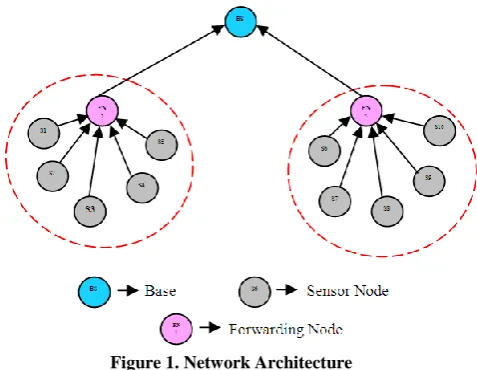
Consider a hierarchical sensor network with a set of sensor nodes S1, S2 … Sn and a base station (BS). The technique
specialising some nodes in the network as forwarding nodes (FN), which are connected and communicated directly with the BS. It is assumed that forwarding nodes (FN) are equipped with extra bandwidth and computing power. Sensor nodes are connected with the forwarding node (FNi) in its transmission
Figure 1. Network Architecture
3.3 Threshold Secret Sharing Scheme
Threshold secret sharing scheme is an essential process for distributing secret key in the network. The traditional Shamir’s secret sharing mechanism necessitates huge storage and incurs heavy computational cost. To avoid the downsides of Shamir’s scheme, the proposed technique utilizes the threshold secret sharing scheme given in [12], which is the enhanced version of Shamir’s scheme.
Consider N as the number of users participating in secret sharing scheme. Let and || be Exclusive OR (XOR) and binary concatenation operator respectively, and P be the prime number and P NU. Let S (X) be the Shannon’s entropy of
variable X and |X| is the number of elements in set X. Consider GF (P) as the Gaussian set that includes indexes of random numbers, divided pieces of secret and number of shares and XORed terms. Let N be the set that contains number of n user and Se be the secret that is to be equally partitioned into P – 1 blocks Se1, Se2 … SeP-1 size r such that,
Se =
0,1r(P1) (1) Consider FN as the set of forwarding nodes that picks a secretSei from Se and distributes a share ai
A
i to every user (sensornode) ni
N. Here, Ai represents the all possible shares thatuser nicould receive. When the anticipated number of user’s n
is a composite number, this scheme makes use of n shares, a0,
a1 … an-1 of (k, P) threshold scheme to generate (k, n) threshold
scheme. Here, k is the arbitrary threshold value and n is the number of users (nodes).
3.3.1 Secret Share Distribution Algorithm
The proposed mechanism assumes that the base station (BS) is secure in nature, it is the repository for all secret Se
0,1 ( 1) rP and accountable for progressing threshold secret
sharing scheme. The algorithm involves the following three steps,
(i) Initially, BS selects a Se and then partition the secret Se into P – 1 pieces of r-bit sequence as Se1 Se2 … SeP-1
0,1r,where, Se0 stands for zero bit sequence Se0 = 0 r and it is also
known as singular point of partitioned pieces of secret. (ii) Second, the algorithm selects (k-1) P-1 parts of r- bit random
number r00,...,rp02,r01,...,rP11,...,r0k2,...,rPk22 from {0, 1} r
individually with unvarying probability of
r
2 1
. BS partitions secret shares as per the following equation,
a (i,j) = xxi j j i
k
x
Se
r
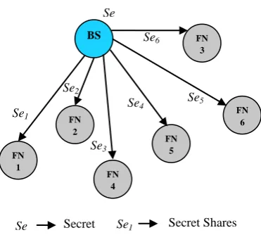
. 2 0 (2) where, 0in1 and 0 jP2. Configuration of secret share of the proposed threshold scheme is given in table-1. (iii) To finish, threshold secret distribution phase, the BS concatenates all pieces and generates secret share ai = a(i,0) || …|| a(i,P-2). Finally, forwards the generated secret share
[image:3.595.103.494.537.687.2]corresponding users FNs by means of secure channel, which will be described later in section (3.4). The general picture of secure scheme distribution is shown in Figure 2
Table 1. Configuration of Secret share generation scheme
j=0 j=1
j=P-2a(0,j) 0 0
2 0 Se rx k x
1 1
2 0 Se rx k x
2 22 0
rx Sek
x
a(1,j) 1
2 0
rxx Sek x 0 1 2 0 Se rxx
k x
2 32 0
rxx Sek x
a(n-1,j) 1 ) 1 .( 2 0
xxn nk
x
Se
r .( 1)1 2
2 0
xxn nk
x
Se
r
.( 1) 2 12 0
xxn nk
x
Se r
Figure 2. Secret Share Distribution Scheme
3.3.2 Recovery Algorithm of Threshold Scheme
The second phase of threshold secret sharing scheme is recovery algorithm. The recovery algorithm encompass the following steps,
Once each secret share is divided about r-bit sequences, a dimensional vector DV of k (P-1) is produced. This vector
symbolizes partioned pieces of secret shares.
A binary matrix R is generated through k (P-1) X k (P-1) using a specific procedure called GEN (Generate). By means of matrix R, secret shares Se1, Se2… Sen are
recovered.
Finally, secret shares Se1, Se2… Sen are joined and the
secret Se is obtained.
3.3.2.1 Generate (GEN) Procedure
This procedure generates the binary matrix R. To accomplish this process, the function GEN () the binary vector Y(Qi,j) of
(kP-2). The vector Y(Qi,j) is attained through indexes Qi and j. It is
the generator vector of a(Q,j), thus a(Q,j) = Y(Qi,j) e, and e can be
represented as,
T P k
P k P
P r r r r Se S
r r
e ( ,..., , ,..., ,... ,..., 12, 1,..., 1) 2
0 1
1 1 0 0
2 0
0
(3)
Using vector Y(Qi,j), another binary vector D of dimension k
(P-1) X (kP - 2) is created as follows,
D(YQ0,0,...,Y(Q0,P2),...,Y(Qk1,0),...,Y(Qk1,P2))T (4) D is the generator matrix of DV, (i.e) DV = D g. Further, by
processing column-wise concatenation the matrix [D, IK(P-1)] is
manipulated and it is transformed into the form of row echelon [
D J ], (i.e)
[D J] = FG ([ D Ik(P-1)])
(5) This is formed by forward elimination step of Gaussian elimination with row operations on GF (2), where, FG() represents the forward elimination function and Ik(P-1) stands for
identity matrix of dimension k(P-1) X k(P-1). Now [D J] matrix is divided into block matrices as,
[
D
J]=
0 0
1 1 2
J D
J D D
(6)
In the above matrix equation D0, D1 and D2 denote block
matrixes of (P-1) X (P-1), (K-1) (P-1) X (P-1) and (K-1) (P-1) X (KP-P-1) dimensions respectively. θ denotes null matrix. J0 is
the block matrix of dimension (P-1) X k (P-1) and J1 of (k-1)
(P-1) X k (P-1).
In the end, backward Gaussian elimination is processed on [D0,
J0]. As a result, we attain,
[IP-1 R] = BG ([D0 J0])
(7) where, BG is the backward substitution and R is the transformed matrix of J0. From the above representation, the
technique can obtain R as output matrix to recover secrets Se1,
Se2 …SeP-1
3.4 Secure Key Transmission Channel
The secure key transmission channel scheme assumes that each sensing node Si (i = 1,2, ..n), BS and FN are preinstalled with
initial secret key Kini and private, public certificates Certpu and
Certpr respectively. Both Certpu and Certpr are produced by
mutually trusted certificate authority (CA). Further, it presumes that BS is the repository of secrets. The symbols and notations used in secure key transmission scheme is given table-2 As soon as nodes are deployed in the network, each FN forms clusters by joining nodes within its transmission range. After time interval ‘t’, FN forwards secret request to the BS. This request includes FNID, FNN, E (Certpu(BS)), MAC Kini (SID),
FNID and FNN.
FN SecretREQBS (8)
Secret REQ: FNID, E(Certpu(BS) (FNN,), MAC Kini (SID || FNID ||
FNN)
On receiving Secret REQ message, the BS decrypts the nonce produced by FN using its Certpr key and verifies the MAC using
initial secret key. If verification is successful, then BS transmits the secret to corresponding FN through Secret reply message. The Secret REP message follows the following format.
FN SecretREPBS (9)
Secret REP : SID, E(Certpu(FN) (Sei), MAC Kini (SID || FNID ||
FNBS)
While getting response message from BS, it decrypt the secret using Certpr(FN) and verifies MAC. Upon successful
verification it accesses the secret value. As soon as accessing the secret, the FN recovers the group key using threshold secret scheme given in section-3.3.
Simultaneously, sensor nodes (Si) within the transmission range
of FNi, transmits group key request (G-REQ) to FNi. The
G-REQ message follows the following pattern.
Si REQ G
FNi (10)
G-REQ: SID, E(Certpu(FN) (SN,), MAC Kini (SID || FNID || SN)
By receiving G-REQ message, FNi performs decryption and
verifies the authentication using initial secret key. Only after the successful authentication, FNi decides to transmit group key. It
sends the group key (GK(i)) using G-REP message.
Si REP G
FNi (11)
G-REP: FNID, E(Certpu(S id) (GK(i)), MAC Kini (SID || FNID || FNN)
Secret
Se6
Se5
Se4
Se3
Se2
Se1
Se
BS FN 3
FN 5
FN 6
FN 4 FN
2
FN 1
The node Si verifies the MAC and then access the group key by
decrypting the value with Certpr (Sid). Each node uses this group
key (GK(i)) for further data transmission in the network. The
obtained group key GK(i) is divided into two keys as private key
(Pri GK(i)) and public key (Pub GK(i)) for further encryption and
decryption process instead of Certpu and Certpr. As sensor
network is highly vulnerable to more security attacks, the generated group key (GK(i)) is periodically refreshed by
considering energy constraint of sensor networks.
[image:5.595.318.533.481.598.2]Since, the group key is divided into n sub keys; the attackers can’t reconstruct the master key if they get less than t sub keys.
Table 2. Symbols and Notations used in Secure Key Transmission Channel Scheme
Symbol Explanation
SID ID of Sensor Node
Certpu
Public certificate produced by Certificate Authority Certpr
Private certificate produced by Certificate Authority
Kini Initial Secret Key
FNID ID of Forwarding Node
BSID ID of Base Station
MAC Message Authentication Code FNN Nonce generated by Forwarding Node
SN Nonce generated by Sensor Node
BSN Nonce generated by Base Station
CA Certificate Authority
The algorithm for overall technique is given below in algorithm-1
Algorithm-1
1. Each sensing node Si (i = 1,2, ..n), BS and FN are
preinstalled with initial secret key Kini and private, public
certificates Certpu and Certpr respectively.
2. Nodes are deployed in the network
3. FN forms clusters by joining nodes within its transmission range
4. FN forwards Secret REQ to the BS
5. If (MAC Kini (SID || FNID || FNN)) is successful then
5.1 Decrypts the nonce value generated by FN 5.2 Transmits back Secret REP message to FN 6. Else if validation is failure Jump to step- 12 7. Each Si forwards G-REQ to FNi
8. FNi performs the validation
9. If (MAC Kini (SID || FNID || SN)) is successful then
9.1 Recovers the group key using threshold secret sharing scheme given in section-3-3
9.2 Includes group key in G-REP message and Transmits back to Si
10. Else if validation is failure Jump to step- 12 11. Si performs validation and accesses group key (GK(i))
12. Terminates secure key transmission process 13. End if
14. GK(i) is refreshed periodically
4. SIMULATION RESULTS
The proposed Hierarchical Group Key Management Using Threshold Cryptography (HGKM-TC) technique is evaluated through NS2 [13] simulation. We consider a random network of 100 sensor nodes deployed in an area of 500 X 500m.The sink node is assumed to be situated 100 meters away from the above specified area. In the simulation, the channel capacity of mobile hosts is set to the same value: 2 Mbps. The simulated traffic is CBR with UDP. The attacker nodes are varied from 2 to 10.
Table 3. summarizes the simulation parameters used
No. of Nodes 100 Area Size 500 X 500 Mac 802.11 Routing protocol EECBKMA Simulation Time 50 sec Traffic Source CBR Packet Size 512 bytes
Rate 250kb
Transmission Range 250m Transmit Power 0.395 w Receiving power 0.660 w Idle power 0.035 w Initial Energy 10.1 Joules No. of Attackers 2,4,6,8 and 10
4.1 Performance Metrics
The performance of HGKMTC technique is compared with the EEKM [11] scheme. The performance is evaluated mainly, according to the following metrics.
Average Packet Drop: The number of packets dropped due to various attacks is averaged over all surviving data packets at the destination.
Average Packet Delivery Ratio: It is the ratio of the number .of packets received successfully and the total number of packets transmitted.
Energy: It is the average energy consumed for the data transmission.
End-to-End Delay: It is the time taken by the data packets to reach the destination from the sender.
4.2 Results
A. Based on Attackers
In our initial experiment, we vary the number of attackers as 2,4,6,8 and 10 from various clusters performing node capture attacks.
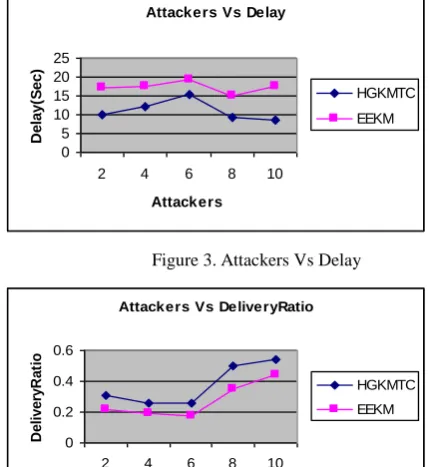
Figure 3. Attackers Vs Delay
Figure 4. Attackers Vs Delivery Ratio
Attackers Vs Delay
0 5 10 15 20 25
2 4 6 8 10 Attackers
D
e
la
y
(S
e
c
)
HGKMTC EEKM
Attackers Vs DeliveryRatio
0 0.2 0.4 0.6
2 4 6 8 10
Attackers
D
e
li
v
e
ry
R
a
ti
o
[image:5.595.317.532.484.718.2]Figure 5. Attackers Vs Drop
Figure 6. Attackers Vs Energy
Figure 7. Attackers Vs Overhead
From figure 3, we can see that the delay of our proposed HGKMTC is less than the existing EEKM technique.
From figure 4, we can see that the delivery ratio of our proposed HGKMTC is higher than the existing EEKM technique.
From figure 5, we can see that the packet drop of our proposed HGKMTC is less than the existing EEKM technique.
From figure 6, we can see that the energy consumption of our proposed HGKMTC is less than the EEKM technique.
From figure 7, we can see that the overhead of our proposed HGKMTC is less than the existing EEKM technique.
5. CONCLUSION
In this paper, a hierarchical group key management technique using threshold cryptography in Wireless Sensor Networks is proposed. The technique considers hierarchical sensor network, where sensing nodes are coordinated by forwarding nodes (FN) and in turn they are connected to the BS. Data transmission in the network is protected through encryption and decryption technique. BS is responsible for key computation and
distribution. FN obtains group key by threshold secret sharing scheme. The acquired group key is divided into multiple shares and shared among member nodes. The obtained group key is divided into two keys for further data encryption and decryption process. Thus, this reduces the possibility of key compromised. The technique is simulated using network simulator 2 (NS-2). Simulation results show the proficiency of our technique.
6. REFERENCES
[1] F. L. Lewis, “Wireless Sensor Networks”, To appear in Smart Environments: Technologies, Protocols, and Applications, ed. D.J. Cook and S.K. Das, John Wiley, New York, 2004.
[2] Mansoor-uz-Zafar Dawood, Noor Zaman, Abdul Raouf Khan and Mohammad Salih, “Designing of Energy Efficient Routing Protocol for Wireless Sensor Network (WSN) Using Location Aware (LA) Algorithm”, Journal of Information & Communication Technology, Vol. 3, No. 2, (Fall 2009) 56-70.
[3] S.Anandamurugan and C.Venkatesh, “Increasing the Lifetime of Wireless Sensor Networks by using AR (Aggregation Routing) Algorithm”, IJCA Special Issue on “Mobile Ad-hoc Networks” MANETs, 2010.
[4] M.Sheik Dawood, S.Sadasivam and G.Athisha, “Energy Efficient Wireless Sensor Networks Based on QoS Enhanced Base Station Controlled Dynamic Clustering Protocol”, International Journal of Computer Applications (0975 – 8887), Volume 13– No.4, January 2011.
[5] Jeremy Elson and Kay Romer, “Wireless Sensor Networks: A New Regime for Time Synchronization”, Proceedings of the First Workshop on Hot Topics in Networks (HotNetsI), 2829 October 2002
[6] Johnson C. Lee, Victor C. M. Leung, Kirk H. Wong, Jiannong Cao and Henry C. B. Chan, “Key Management Issues In Wireless Sensor Networks: Current Proposals and Future Developments”, IEEE Wireless Communications • October 2007.
[7] Wenjun Gu, Neelanjana Dutta, Sriram Chellappan, and Xiaole Bai, “Providing End-to-End Secure Communications in Wireless Sensor Networks”, IEEE Transactions on Network and Service Management, Vol. 8, No. 3, September 2011.
[8] Jia Hu, Enjian Bai and Yang Yang, “A Novel Key Management Scheme for Hierarchical Wireless Sensor Networks”, Communication Technology (ICCT), 2010 12th IEEE International Conference on Date of Conference: 11-14 Nov. 2010.
[9] Shu Yun Lim and Meng-Hui Lim, “Energy-Efficient and Scalable Group Key Management for Hierarchical Sensor Network”, Journal of Ubiquitous Systems & Pervasive Networks Volume 2, No. 1 (2011) pp. 39-47.
[10]Tim Landstra, Sarangapani Jagannathan, and Maciej Zawodniok, “Energy-Efficient Hybrid Key Management Protocol for Wireless Sensor Networks”, International Journal of Network Security, Nol.9, No.2, PP.121-134, Sept. 2009.
[11]Kwang-Jin Paek, Jongwan Kim, Chong-Sun Hwang, SangKeun Lee and Ui-Sung Song, “Group-Based Key Management Protocol For Energy Efficiency In Long-Lived And Large-Scale Distributed Sensor Networks”, Computing and Informatics, Vol. 27, 2008, 743–756.
Attackers Vs Drop
0 5000 10000 15000
2 4 6 8 10 Attackers
P
k
ts HGKMTC
EEKM
Attackers Vs Energy
0 5 10 15
2 4 6 8 10 Attackers
E
n
e
rg
y
(J
)
HGKMTC EEKM
Attackers Vs Overhead
0 5000 10000 15000
2 4 6 8 10 Attackers
O
v
e
rh
e
a
d
[12]Jun Kurihara, Shinsaku Kiyomoto, Kazuhide Fukushima, and Toshiaki Tanaka, “A New (k, n)-Threshold Secret Sharing Scheme and Its Extension”, Proceedings of the
11th international conference on Information Security, (ISC '08), pp- 455 – 470, 2008.