Volume 2010, Article ID 753129,14pages doi:10.1155/2010/753129
Research Article
TOA Estimator for UWB Backscattering RFID System with
Clutter Suppression Capability
Chi Xu and Choi L. Law
Positioning & Wireless Technology Centre, Nanyang Technological University, 50 Nanyang Drive, Research TechnoPlaza, Level 4, BorderX Block, Singapore 637553
Correspondence should be addressed to Chi Xu,[email protected]
Received 23 November 2009; Revised 20 April 2010; Accepted 9 May 2010
Academic Editor: Richard Kozick
Copyright © 2010 C. Xu and C. L. Law. This is an open access article distributed under the Creative Commons Attribution License, which permits unrestricted use, distribution, and reproduction in any medium, provided the original work is properly cited.
Time of arrival (TOA) estimation in multipath dense environment for UWB backscattering radio frequency identification (RFID) system is challenging due to the presence of strong clutter. In addition, the backscattering RFID system has peculiar signal transmission and modulation characteristics, which are considerably different from conventional communication and localization systems. The existing TOA estimators proposed for conventional UWB systems are inappropriate for the backscattering RFID system since they lack the required clutter suppression capability and do not account for the peculiar characteristics of backscattering system. In this paper, we derive a nondata-aided (NDA) least square (LS) TOA estimator for UWB backscattering RFID system. We show that the proposed estimator is inherently immune to clutter and is robust in under-sampling operation. The effects of various parameter settings on the TOA estimation accuracy are also studied via simulations.
1. Introduction
Backscattering radio frequency identification (RFID) is a type of RFID technology employing tags that do not generate their own signals but reflect the received signals back to the readers. It is widely used in asset tracking, inventory management, health care monitoring, and other fields [1]. Nowadays many RFID applications such as context-aware healthcare require accurate location information with extended operating range. The conventional backscatter-ing RFID system usbackscatter-ing continuous wave (CW), however, cannot fulfill this requirement due to its poor distance estimation accuracy and limited operating range. Recently, ultra wideband (UWB) signal emerges as a viable solution for the new generation of backscattering RFID system. UWB is defined by Federal Communications Commission (FCC) as signals having a fractional bandwidth larger than 20% or absolute bandwidth of more than 500 MHz [2]. Such enormous bandwidth brings many advantages such as higher ranging accuracy, lower probability of interception, and more resistance to multipath fading as compared to CW signal [3]. Its capability in achieving accurate range
and location estimation has been proven analytically and in experiments [4–7]. UWB signal has been applied to backscattering RFID system with localization functionality in [8, 9]. In [8], the concept of UWB pseudorandom backscattering tag is introduced. The tag receives signal only in certain time interval according to a pseudoran-dom time hopping sequence, slightly delays it and then reflects it back to the reader. In [9], a UWB backscat-tering RFID tag that is able to apply various modulation schemes is proposed and its potential operating range/data rate tradeoff in the presence of strong clutter is investi-gated.
To clean the received signal contaminated by clutter before applying any TOA estimation algorithm, the empty-room or frame-to-frame techniques used in the radar community may be applied [11]. The empty-room technique subtracts the channel response measured in the absence of the target from any received signal comprising of both target response and clutter. Unfortunately, this technique is sensi-tive to environment changes since any change renders the previously measured empty-room response inappropriate for further use. For the frame-to-frame technique, each measurement consists of two received signals captured at different timings. The technique subtracts one signal from the other to eliminate the clutter that is assumed to be static in each measurement but may change from measurement to measurement. This technique fails if the target does not move or moves little between received timings of the two signals in the same measurement. Besides the empty-room and frame-to-frame techniques, it is also possible to mitigate clutter by proper selection of the modulation sequence used by the tags. In [9], it is shown that if the tag’s modulation sequence for antipodal 2-PAM signaling fulfills certain criteria, by averaging over multiple symbols, the received signal is immune to clutter. The study, however, is carried out in the context of data communication under the assumption that perfect pulse synchronization to the first arriving path is achieved, that is, TOA information is known.
There are many existing TOA estimators proposed for UWB system. The channel estimators derived in [12, 13] are able to estimate the delays of the paths and hence can be implicitly used as TOA estimators. A generalized maximum likelihood (GML) estimator is proposed in [14], which performs the channel estimation in a predefined time interval prior to the largest sample and takes the timing of the first channel tap crossing a preset threshold as TOA. The subspace-based TOA estimators are pursued in [15,
16]. Frequency-domain super-resolution TOA estimation with diversity techniques is studied for indoor localization applications in [17]. The computational complexity of the above estimators is high due to their requirements of either estimation of large number of multipath, or eigen value decomposition of matrices with large dimension. Recent works of TOA estimation focus on the develop-ment of low-complexity algorithms. A few suboptimal TOA estimation algorithms with reduced computational complexity are introduced in [18,19]. The cyclostationarity nature of UWB signal is exploited to develop non-data-aided (NDA) TOA estimators [20, 21]. A novel “timing with dirty template” (TDT) synchronization criterion is established in [22] based on which both data-aided (DA) and NDA estimators are derived. As shown in [23], it is also possible to transform timing estimation into a maximum likelihood (ML) amplitude estimation problem and derive a closed form solution for the frame level timing offset. A few threshold-crossing TOA estimators applicable for energy detection (ED) receiver are developed in [24–
26]. In [24], a normalized threshold selection adapted to the strength of the received channel profile is proposed. In [25], a threshold selection method based on
Kurto-sis value is developed which is proven to be robust to channel condition variation. In [26], the threshold is set as a function of propagation delay and simulation results show that considerable performance improvement can be achieved over conventional methods. A TOA estimator allowing long energy integration duration is derived based on unknown pulse shape and GML criterion [27]. Based on least square (LS) criterion, TOA estimators for UWB system are derived in [28,29]. To speed up the estimation process, different two-stage estimators are proposed where the first stage estimates a coarse TOA and the second stage refines the result [30, 31]. An excellent literature review of UWB TOA estimation is presented in [32]. All these TOA estimators, however, are derived in the context of conventional UWB system which involves one-way channel propagation and the signal modulations are done at the transmitter. Therefore, the channel response to a single transmitted UWB pulse only contains the information of a single data bit. The UWB backscattering RFID system, how-ever, presents a different propagation scenario. It involves roundtrip channel propagation and the signal modulation is performed at the tag which lies in the middle of the roundtrip channel. If the clock of the backscattering tag does not synchronize with the clock of the reader, such modulation incurs mismatch, that is, the front part of a channel response received at the tag may be modulated by one bit while the tail is modulated by the next data bit. Hence the received signal model of UWB backscattering system is significantly different from that of conventional UWB system. Furthermore, the aforementioned TOA estimators do not include clutter in their signal models during the derivation processes and hence they lack of proven clutter suppression capability. Consequently, those TOA estimators cannot be directly applied to UWB backscattering RFID system.
According to the above discussion, the peculiar transmis-sion and modulation characteristics of UWB backscattering system together with the clutter suppression requirement call for a dedicated treatment of the derivation for TOA estimator. With these requirements in mind, we derive a novel NDA LS TOA estimator for the UWB backscat-tering RFID system with antipodal 2-PAM based on the tag structure proposed in [9]. The proposed estimator is able to recover the TOA information even when the clocks of readers and tags are asynchronous. By exam-ining the properties of the derived estimator, we find that it has inherent immunity to clutter for arbitrary data sequence which is highly desirable for backscat-tering RFID system. Unlike the aforementioned empty-room and frame-to-frame techniques, such immunity holds regardless of environment changes and does not matter if the tags move or keep stationary. Simulation results indicate that the estimator is robust in undersampling operation.
The rest of the paper is organized as follows.Section 2
describes the system model and signal model. Section 3
derives the LS estimator whose immunity to clutter is discussed in Section 4. Simulation results are presented in
+1 +1
+1 +1
Tf
Reader Tx antenna
Tx
Rx CLK
Scatterer
Rx antenna
Environment clutter +1 +1
+1 +1
−1 +1 −1 +1
Structural mode scattering
Antenna mode scattering
Tag antenna
Tag
2-PAM modulator
Bipolar sequence generator
Figure1: System block diagram.
2. System Model and Signal Model
Here, we derive a NDA LS TOA estimator for the UWB backscattering RFID system with the tag proposed in [9], assuming that the clocks of the reader and tag are asynchronous. Tags under consideration are implemented with antipodal 2-PAM modulators. To initialize the TOA estimation, a reader transmits UWB pulses to a targeted tag and estimates the TOA of the roundtrip channel response. As depicted inFigure 1, the returned roundtrip tag response (including direct transmission and channel echoes) is con-taminated by the clutter reflected directly by surrounding scatterers without passing through the tag [10]. With the TOA metric recovered from the received signal, the range between the reader and the tag can be calculated. The range measurements from different readers can be combined to estimate the location of the desired tag. Without loss of generality, we will focus on the TOA estimation between one reader and one tag.
As illustrated in Figure 1, the tag under consideration consists of an antenna, an antipodal 2-PAM modulator and a bipolar sequence generator with output being +1 or−1. The load condition of the tag antenna is determined by the 2-PAM modulator which is controlled by the sequence generator. The 2-PAM modulator retains the polarity of its input signal if +1 is generated by the sequence generator, and it inverts the polarity if −1 is generated. The tag antenna acts like a scatterer and its scattering mechanism can be classified as structural mode and antenna mode [33]. The structural mode scattering is solely determined by the physical properties of the antenna and is independent of the load condition of the antenna. Thus the signal caused by structure mode scattering cannot be modulated by the 2-PAM modulator and hence does not carry any data information in the tag. In contrast, the signal incurred by the antenna mode scattering is received by the antenna and modulated with a bipolar sequence generated by spreading
a ranging sequence {ai = ±1} with a pseudonoise (PN) code{cj = ±1}which has periodNf, that is,cj+Nf = cj,
for all j. The PN code {cj} is unique for each tag and is used for multiuser interference suppression or spectrum smoothing. The ranging sequence {ai} is periodic with periodNa. In the following discussion, the tag response refers to the signal caused by the antenna mode scattering while the unmodulated signal caused by the structural mode scattering is treated as part of the clutter.
To initialize the TOA estimation process, the reader repetitively sends UWB pulses starting at timingt=0 with respect to its own clock. Every symbol consists ofNf frames with one pulse per frame. The transmitted signal is given by
s(t)=
i Nf−1
j=0
ptxt−iNf +j
Tf
, (1)
where ptx(t) is the transmitted UWB pulse and Tf is the frame duration.
After propagating through the downlink channel (from reader to tag), the transmitted signal with its channel echoes arrives at the tag. Let Ld be the number of paths in the downlink channel. The downlink channel response toptx(t) is modeled as
hd(t)= Ld−1
l=0
p(dl)t−τd(l)rel, (2)
wherepd(l)(t) is the pulse of thelth path,τ (l) drel=τ
(l)
d −τdis the associated relative path delay,τd(l)andτdare the propagation delays of thelth path and the direct path, respectively.hd(t) has a support region on [0,Tds(true)] and T
(true)
(a) s(t)
ptx(t)
Tf
(b) Modulation sequenceΦ(t)
vNfTf+uTf ρ
1
−1
Tf−ρ
a0c0 a0c1 a0c2 a1c0
Transition edges between data bits (c) rtg(t) (input to
2-PAM modulator)
τd+τtg
ϑ0(t) ϑ1(t)
(d) stg(t) (output of
2-PAM modulator)
Ψ0,0(t) Ψ0,1(t) Ψ0,2(t)
(e) Received signals at reader
q(t) g0,0(t) g0,1(t) g0,2(t)
ttoa
Figure2: Transmited/received signals present at various stages of the RFID system. (For (e), the clutter signal and the tag response are
displayed separately).
the modulator. The noise-free signal fed to the modulator of the tag is expressed as
rtg(t)=
i Nf−1
j=0 hd
t−iNf+j
Tf −τd−τtg
. (3)
LetΩ(t) be a rectangular window with unit amplitude int∈
[0, 1] and zero elsewhere. As illustrated inFigure 2(b), the modulator function of the tag is given by
Φ(t)=
i Nf−1
j=0 aicjΩ
1 Tf
t−iNf +vNf +j+u
Tf
+Tf−ρ
,
(4)
wherevanduare integers denoting the ranging symbol offset and PN code offset between the reader and the tag, ρ ∈
[0,Tf) is the timing offset between the clocks of the reader and the tag. Let|x|ybe the modular operation(x) modyand
·be the integer floor operation. Equivalently, (4) may be also written as
Φ(t)=
i Nf−1
j=0
Λi,j
t−iNf +vNf+j+u
Tf
, (5)
whereΛi,j(t)=aicjΩ(t/ρ) +ai+(j+1)/Nfc|j+1|N fΩ((t−ρ)/(Tf − ρ)) has time support on [0,Tf]. The output of the modulator is expressed as
stg(t)=rtg(t)Φ(t). (6)
Substituting (3) and (5) into (6) yields
stg(t)=
i Nf−1
j=0
Ψi,j
t−iNf +vNf+j+u
Tf −τd−τtg
,
(7)
whereΨi,j(t)= aicjϑ0(t) +ai+(j+1)/Nfc|j+1|N fϑ1(t),ϑ0(t) =
Ω((t+τd+τtg)/ρ). Similarly, forτd+τtg +Tds(true)< ρ < Tf, we haveϑ1(t)=0.
Letτtg be the delay from the output of the modulator to the transmitting antenna of the tag. The modulated tag response stg(t) is delayed by τtg seconds and retransmitted back to the reader via the uplink channel (from tag to reader). Assuming that the uplink channel hasLupaths, its responses toϑ0(t) andϑ1(t) are given by are the relative propagation delays associated with p(ul0) and p(ul1), τu is the propagation delay of the direct path in the uplink channel, andτu(l0)andτ
(l)
u1are the propagation delays of thelth path. As illustrated inFigure 1, besides the returned tag response, the reader also inevitably receives clutter. The clutter has consistent waveform over different frames since it is not modulated by the tag. The clutter channel response to a single transmitted UWB pulseptx(t) is
q(t)= is the number of clutter paths. q(t) has time support on [τq(0),τq(0)+Tg], whereTg is the maximum clutter spread.
Let us define the true TOAttoa as the arrival timing of the returned direct path in response to the pulse transmitted at t = 0. By this definition, ttoa is equal to the roundtrip propagation delay plus the processing delay of the tag, that is, ttoa=τd+τu+τtg, whereτtg=τtg +τtgis the total processing delay of the tag. For ranging applications,τtgmay be known by the reader via precalibration or communications between the tag and the reader so that eventually it can be calibrated out of estimated ttoa. Assume that ttoa follows a uniform distribution, that is, ttoa ∼ U(0,Tmax), where Tmax is the maximum TOA. After passing through a zonal bandpass filter with bandwidthW, the overall signal received by the reader can be expressed as
r(t)=
wherew(t) accounts for thermal noise and multiple access interference, the double-sided power spectral density ofw(t) ofN0/2,η(t) = i
Nf−1
j=0 q(t−(iNf + j)Tf) is the overall clutter waveform withq(t) defined in (9),gi,j(t)=aicjx(t) +
ai+(j+1)/Nfc|j+1|N f y(t) is the uplink channel response to Ψi,j(t) and can also be interpreted as the overall roundtrip tag response to the UWB pulse transmitted att=iNfTf +jTf, x(t) andy(t) have been defined in (8).
In the above derivation, we have assumed that the uplink channel has the same true maximum one-way channel delay spreadTds(true) as the downlink channel. We further assume thatTg ≤Tf andTmax+ 2Tds(true)≤Tf so that the interframe interference (IFI) is avoided. As implied by (10), the tag response energy may vary for different frames since the data bits modulating x(t) and y(t) may be different. It is useful to define an averaged symbol energy to noise ratio SNR = Es/N0, where Es is the energy per symbol of the tag response averaged over all possible data bits, that is, Es = NfE[
Tf
0 gi2,j(t)dt]= Nf Tf
0 (x2(t) +y2(t))dtandE[·] is the expectation operator. Another parameter of interest is the signal-to-clutter ratio SCR = Es/(NfEq), whereEq = Tf
0 q2(t)dtandNfEqis the energy per symbol of the clutter.
3. LS TOA Estimation
In this section, a LS TOA estimator is derived based on Tds which is the presumed maximum delay spread of the one-way channel. Generally, Tds is not equal to its true valueTds(true). As shown inSection 5, the discrepancy between Tds andTds(true) does affect the estimation accuracy and the optimum value ofTdsmay be determined via simulation.
The received wave formr(t) expressed in (10) is sampled at frequency fs=1/Δwith corresponding periodΔ=Tf/N, where N is the total number of samples per frame. r(t) is observed over time durationNsNfTf and is sampled at timings t = mNfTf +nTf +kΔwith m = 0, 1,. . .,Ns− 1, n = 0, 1,. . .,Nf − 1, and k = 0, 1,. . .,N. Here, Ns is the number of observed symbols and is assumed to be integer multiples of the ranging sequence’s period Na, that is, Ns = NaQ and Q is an integer. The reason for considering multiple symbols for TOA estimation is to provide processing gain to suppress noise. The channels for both the tag response and clutter are assumed to be static during the sampling duration. The sample vector in the nth frame of the mth symbol interval is denoted as
rm,n=[rm,n[0],rm,n[1],. . .,rm,n[N−1]]T. LetM = ttoa/Δ andNds = 2Tds/Δ. Letx = [x[0],x[1],. . .,x[Nds−1]]T and y = [y[0],y[1],. . .,y[Nds−1]]T be the sample vectors of x(t) and y(t). Define two column vectors
px(M)=[0TM×1,xT,0T(N−M−Nds)×1] T
andpy(M)=[0TM×1,yT,
0T(N−M−Nds)×1]
T, where0represents a column vector with all
elements being zeros. Both px(M) and py(M) contain N elements each.rm,nmay be modeled as
rm,n=gm,n(u,v,M) +q+wm,n, (11)
gm,n(u,v,M) is the sample vector of tag response and is given by
gm,n(u,v,M)=Cm,n(u,v)px(M)+Cm,n+1(u,v)py(M). (12)
Here,Cm,n(u,v)=am−v+(n−u)/Nfc|n−u|N fandCm,n+1(u,v)=
am−v+(n+1−u)/Nfc|n+1−u|N f are data bits modulating the
par-tial tag responsesxandy, respectively.
To proceed, let{M,x,y,u, v,q}be the candidate values of parameters {M,x,y,u,v,q} among which M is the parameter of interest whereas the rest are nuisance param-eters.{M,x,y,u, v,q}are chosen to minimize the following
where the norm operator z computes the Euclidean distance of vector z. The search for global minimum of a general multidimensional nonlinear function usually involves numerical searching using the genetic algorithms, grid searchers or other computational intensive algorithms. Fortunately, the nonlinear cost function (13) has some special properties that allow us to first reduce the variables set to be optimized from {M,x,y,u,v,q} to {M,u, v}, which drastically reduces the computational complexity. This reduction procedure can lead to the global minimum of the cost function. The simplified cost function with the reduced variable set{M,u, v}is then minimized by searching over all possible discrete values of the variables to reach the global minimum. The details of minimization procedure are given as follows.
The cost function Υ(M,x,y,u, v,q) has two special properties. The first property is that it is a general con-vex quadratic function of q. By substituting (12) into (13), it can be readily shown that the nonlinear function
Υ(M,x,y,u,v,q) can be transformed into the following The second property is that the cost function is twice continuously differentiable with respect to q. This can be readily shown by differentiating (14) twice with respect to
q, which yields
∂2ΥM,x,y,u, v,q
∂q2 =NsNf. (15)
The treatments for such special unconstrained convex opti-mization problem can be found in many books such as
[34]. For such special convex function of q, the partial differentiation equation with respect to the variable q leads to the global minimum of the function. For this reason, we can substitute the solution of partial differential equation∂Υ(M,x,y,u, v,q)/∂q = 0 into (13) to eliminate vector containing the samples averaged overNsNf frames,
As shown inAppendix A
Ax(u,v) =Ay(u,v)=Q Equation (16) is rewritten as
Before proceeding to the next step, let us first define a few terms that will be used in the later discussions
With equations (19)–(22), by substituting q = q into (13) and dropping the factor (m
nrm,n2)− θ2which is irrelevant to the decision-making process, we reach
ΥM,x,y,u, v,q observed samples, the ranging and the PN codes.
Similar to the original cost functionΥ(M,x,y,u, v,q), the intermediate function Υ( M,x,y,u, v,q) expressed in (23) also fulfills the two special properties. First, Equation (23) may be transformed into convex quadratic forms ofxandy.
ΥM,x,y,u, v,q=1 it can be readily shown that (24) is twice differentiable about
xandy, respectively. According to the previous discussions, we may conclude that the solutions of the two partial differentiation equations ∂Υ(M,x,y,u, v,q)/∂x = 0 and
Solving (25) gives the following intermediate expressions for tag response: (23) and simplifying, we have the following expression for
Υ(M,x,y,u,v,q) depending only on{M,u, v}: exceptional situation, the following analysis is carried out. The equationγ2 Next, we will give some intuition for these two conditions. The conditionCm,n(u,v) = Cm,n+1(u,v), for all m,nis met when every bit in the sequence {Cm,n(u,v)}has the same polarity, that is,Cm,n(u,v)=+1, for allm,norCm,n(u,v) =
−1, for all m,n. In this case the tag response will retain polarity over different frames, appearing as “unmodulated” signal like clutter. Therefore, there is no way the tag response can be distinguished from the clutter, which is undesired. In the following discussion, we assume that such undesired sequence is deliberately discarded in the system design so that F /=NsNf applies. The second condition Cm,n(u,v) + Cm,n+1(u,v) = 0, for allm,nis fulfilled when{Cm,n(u,v)} consists of alternative +1 and −1, that is, it is a sequence of+1,−1, +1,−1,. . .. With such sequence, we have A =
0, F= −NsNf andBk(u,v)= −Dk(u,v). Together with ( 23), it is straightforward to show that
ΥM,x,y,u, v,q=NsNfx−y2−2θTB
where{M,u, v}are the final estimates of{M,u,v}. And the TOA is estimated as
ttoa=ΔM. (35)
Equation (34) indicates that the final solution involves a minimum search procedure over a three-dimensional space span by variables{M,u,v}. The complexity of this searching procedure is proportional to the number of possible discrete values ofM,u, and v, that is, proportional to the maximum number of samples prior to the TOA samplefsTmax, the number of symbolsNs, and the number of frames per symbol Nf. ReducingfsorNscan lower the computational complex-ity. As a tradeoff, the TOA estimation accuracy will decrease accordingly. However, the simulation results in Section 5
will reveal that the TOA performance is very robust to the reduction in fsand is reduced by only about 3 dB for halving Ns. ReducingNf also reduces the computational complexity which causes insignificant variation of TOA estimation as shown in the simulation results in Section 5. Therefore, our scheme does not require large Nf and Nf should be minimized for TOA estimation during system design phase. This minimum value ofNf should be determined by other aspects of system design such as spectrum smoothing or the number of users in the system, which is out of the scope of this paper. Hence, by carefully setting fs, Ns, and Nf, satisfactory performance can be achieved with reasonable complexity.
4. Immunity of the Estimator to Clutter
Any TOA estimator for UWB backscattering RFID system should posses clutter suppression capability, especially in an environment with dense scatterers. In [9], for data communi-cation applicommuni-cations, clutter is suppressed by choosing a data sequence with zero mean (or quasi-zero mean). Intuitively we would have expected that similar sequence selection should also be imposed to ensure that the estimator derived inSection 3is immune to clutter. However, we are going to show that the derived estimator is indeed inherently immune to clutter for arbitrary data sequence.
Note that the final decision functionΥ(M,x,y,u,v,q) reveal the possible effects of the clutter term {q[k]} on
Υ(M,x,y,u, v,q) given in (27), the signal model rm,n[k] given in (11) is substituted into (27), which yields
ΥM,x,y,u, v,q symbolic term {q[k]}have been completely cancelled out during the derivation process, leaving no clutter term in the final expression. This finding suggests that clutter does not have any effect on the value of decision function. Therefore, the decision function (27) is immune to the clutter.
Next, to prove that (33) is immune to the clutter, we recall that (33) is used forCm,n(u,v) + Cm,n+1(u,v) =0, for allm,n decision function (33) is also irrelevant to the clutter.
Consequently, based on the above discussions, it can be concluded that the proposed estimator is immune to the clutter. This conclusion is also supported by the simulation results presented in the next section.
5. Simulation Results
For the tag response, the impulse responses of both downlink and uplink channels are generated from the channel models CM1 for residential LOS environment and CM2 for resi-dential NLOS environment as described in IEEE802.15.4a standard [36]. The lengths of the generated one-way channel impulse responses are truncated beyond 60 ns, that is, Tds(true) = 60 ns which is the same setting as used in [28] and can capture 99.97% and 90.87% of total channel energy of CM1 and CM2, respectively. Since no UWB channel model for clutter has been reported in the literature, the impulse response of the clutter channel used in simulations is generated as follows. LethIRq(t) be the impulse response of the clutter.hIRq(t) is generated by
hIRq(t)=hIR(t)⊗hIR(t)⊗δ
t−tq
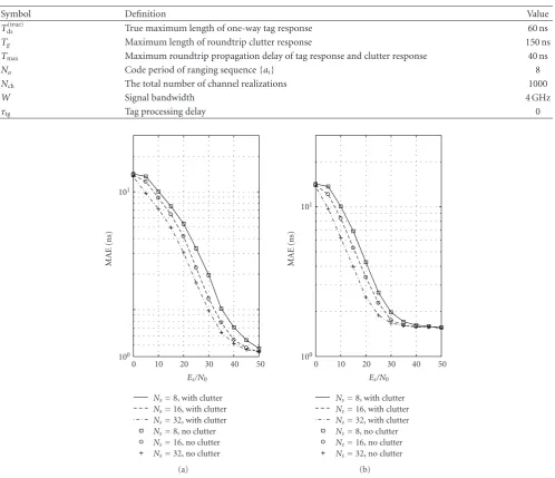
Table1: Summary of Adopted Symbols for Simulation.
Symbol Definition Value
Tds(true) True maximum length of one-way tag response 60 ns
Tg Maximum length of roundtrip clutter response 150 ns
Tmax Maximum roundtrip propagation delay of tag response and clutter response 40 ns
Na Code period of ranging sequence{ai} 8
Nch The total number of channel realizations 1000
W Signal bandwidth 4 GHz
τtg Tag processing delay 0
100
101
MAE
(ns)
0 10 20 30 40 50
Es/N0
Ns=8, with clutter Ns=16, with clutter Ns=32, with clutter Ns=8, no clutter Ns=16, no clutter Ns=32, no clutter
(a)
100
101
MAE
(ns)
0 10 20 30 40 50
Es/N0
Ns=8, with clutter Ns=16, with clutter Ns=32, with clutter Ns=8, no clutter Ns=16, no clutter Ns=32, no clutter
(b)
Figure3: Performance comparison of the estimator under the scenarios with and without clutter for different number of sampled symbols
in CM1 (a) and CM2 (b) withTds=45 ns,fs=8 GHz,Nf =4, and SCR=−30 dB.
where ⊗is the convolution operator, and hIR(t) is a one-way channel impulse response generated independently and randomly from the CM1 and CM2 channel models used for the tag response generation, δ(t) is a Dirac delta function andtqis the propagation delay of the first path in the clutter. Assume thattq follows a uniform distribution, that is,tq ∼ U(0,Tmax). The length of clutter responses are truncated beyond Tg = 150 ns which is slightly longer than the true maximum roundtrip delay spread of tag responses 2Tds(true)= 120 ns.
The transmitted UWB pulse is shaped as the second derivative of Gaussian pulse with width of 1 ns. Without loss of generality, we set the tag processing delay to zero in the simulation, that is, τtg = 0 ns. The rest of system settings are W = 4 GHz, Tmax = 40 ns, Tf = 200 ns, Na = 8.
For each channel realization, the sequence{ai}and{cj}are randomly generated. The TOA estimation error for theκth channel realization isεκ =ttoa−ttoaand the mean absolute error (MAE) defined by MAE =(1/Nch)Nch−1
κ=0 |εκ|is used as performance criterion where Nch is the total number of channel realizations and is set to 1000 in the simulation. The symbols adopted in the simulations are summarized in
Table 1.
100
101
MAE
(ns)
0 5 10 15 20 25 30 35 40 45 50
Es/N0(dB)
Nf=1 Nf=2
Nf =4 Nf =8
Figure4: Performance comparison with differentNf in CM1 with
Tds=45 ns,fs=8 GHz, and SCR=−30 dB.
100
101
MAE
(ns)
20 25 30 35 40 45 50 55 60
Tds(ns)
Es/N0=10 dB
Es/N0=15 dB
Es/N0=20 dB
Es/N0=25 dB
Es/N0=30 dB
Es/N0=35 dB
Es/N0=40 dB
Es/N0=45 dB
Es/N0=50 dB
Figure 5: MAE versus channel delay spread setting for different
SNR in CM1 withNs=8,Nf =4, andfs=8 GHz.
Figure 3indicates that the MAE of CM1 is generally lower than that of CM2 especially in the high SNR region. The reason is that the direct path is statistically stronger in CM1 than in CM2 due to the obstacles in CM2 environment that may severely attenuate the direct path. It can also be observed that using more symbols improves the performance of the estimator. In both CM1 and CM2, for a large range of SNR, doubling the number of sampled symbols results in 3 dB less SNR to achieve a given MAE.
100
101
MAE
(ns)
15 20 25 30 35 40 45 50
Es/N0(dB)
fs=8 GHz,Tds=40 ns
fs=4 GHz,Tds=40 ns
fs=2 GHz,Tds=40 ns
fs=1 GHz,Tds=40 ns
fs=8 GHz,Tds=50 ns
fs=4 GHz,Tds=50 ns
fs=2 GHz,Tds=50 ns
fs=1 GHz,Tds=50 ns
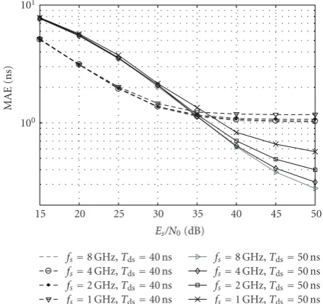
Figure6: Effect of sampling frequency on MAE in CM1 withNs
=16 andNf =4 forTds=40 ns (dash line) andTds=50 ns (solid
line).
Figure 4investigates the effects of the number of frames per symbol Nf on the performance with Tds = 45 ns, fs = 8 GHz, and SCR = −30 dB. As Nf increases from 1 to 8, the variation of MAE is insignificant which suggests that the impact ofNf on the estimation accuracy is trivial. Moreover, according to (34), the computational complexity of the proposed estimator increases asNf increases. Hence Nf should be minimized for TOA estimation purpose during system design phase.
Setting of the presumed maximum one-way channel delay spreadTdsis closely related to the performance of TOA estimation since it directly determinesNdswhich is included in the discrete signal model used to derive LS estimator.
Figure 5presents the results of MAE versusTdsfor different SNR values in CM1 channels which have RMS delay spread of around 17 ns. The system settings areNs=16 andNf =4. There is an optimal setting ofTdsfor every SNR curve. This optimal setting ranges from 25 ns to 50 ns as SNR varies from 10 to 50 dB and it increases as SNR increases. The MAE is much more sensitive to the setting ofTdsfor signal with high SNR.
100
101
MAE
(ns)
−30 −20 −10 0 10 20 30 SCR (dB)
ED normalized,ξnorm=0.05
ED normalized,ξnorm=0.1
ED normalized,ξnorm=0.2
GML,Tint=60 ns
GML,Tint=80 ns
GML,Tint=100 ns
This paper,Tds=40 ns
This paper,Tds=45 ns
This paper,Tds=50 ns
Figure 7: Performance comparison of different TOA estimators
in CM1: (1) ED estimator with normalized threshold (solid line); (2) estimator derived based on GML criterion (dash line); (3) the estimator proposed in this paper (dash-dot line). The settings are Es/N0=35 dB,Ns=8,Nf =4,Δ=1 ns,TGML=1 ns, andTED=1ns,
Tsb=40 ns.
InFigure 7, we compare the performance of the estimator proposed in this paper with two estimators proposed in [24,
27]. The two estimations are described as follows. The TOA estimator developed in [24] passes the received waveform to a square-law device, integrates the output successively with time intervalTEDto obtain energy samples and then searches the direct path sample within a time period prior to the strongest sample. Note thatTED is the time resolution for this estimator. The search back window is denoted asTsband the number of energy samples within the windows areNsb= Tsb/TED. The first sample crossing a predefined normalized threshold γnorm is detected as the direct path sample. The energy samples for this estimator can be expressed as
zED[k]=
Ns−1
m=0 Nf−1
n=0
t=mNfTf+nTf+(k+1)TED
t=mNfTf+nTf+kTED
|r(t)|2 dt,
k=0, 1,. . .,
Tf TED
−1. (41)
The normalized thresholdγnormis defined by
γnorm=min[zED[k]] +γnorm(max[zED[k]]−min[zED[k]]), (42)
where min[zED[k]] and max[zED[k]] are minimum and maximum samples among{zED[k]}. The TOA is estimated as
ttoa=TEDmink|zED[k]> γnorm−0.5
+(kmax−Nsb−1)), ∀k−Nsb≤k≤kmax, (43)
wherekmax=arg maxk[zED[k]]. This estimator is referred to as ED estimator with normalized threshold hereafter.
The estimator presented in [27] is derived based on GML criterion with the assumption that the shape of the received waveform is unknown. The estimator performs energy integrations successively with long time durationTint comparable to the delay spread of propagation channel. Unlike the estimator in [24], the time intervals of the inte-grations are allowed to overlap with each other if multiple integrators are implemented in parallel. The starting timings of two adjacent integrations are separated by a fixed delay TGMLwhich determines the time resolution. The samples are
zGML[k]=
Ns−1
m=0 Nf−1
n=0
t=mNfTf+nTf+kTGML+Tint
t=mNfTf+nTf+kTGML
|r(t)|2dt,
k=0, 1,. . .,
Tf TGML
−1. (44)
The arrival timing of the maximum sample is taken as TOA
ttoa=TGML
arg max
k [zGML[k]]−0.5
,
∀0≤k≤
Tmax TGML .
(45)
Among the two estimators, the ED estimator with normalized threshold is more robust to the channel and noise variation since its adaptive threshold setting while the estimator derived based on GML criterion can poten-tially achieve higher resolution in practical system since it decouples the time resolution from the length of integration interval and the short interval is difficult to be implemented due to receiver hardware limitation [27].
6. Conclusion
A novel NDA LS TOA estimator is proposed as a solution to overcome the undesired clutter signal for TOA estimation problem in UWB backscattering RFID system. Both theoret-ical study and simulation results indicate that the estimator is inherently immune to the clutter signal regardless of SNR variation. Simulation results also show that the performance of the estimator depends on the number of sampled symbols as well as the presumed channel delay spread setting. Also the study shows that the estimator is robust over undersampling operation.
Appendices
A.
To prove (18), using conditionsam =am+NaandNs=QNa,
it can be shown that
Ax(u,v)=
Analogous to the proof forAx(u,v), we can also show that Ay(u,v) = Q(
Therefore, (A.3) may be rewritten as
F(u,v)=QNa
To get more insight into the second equation, we invoke the Cauchy-Schwarz inequality which states that |ixiyi|2 ≤ (i|xi|2)(
i|yi|2) is always true and the equality holds if and only if xi/ yi = xi/ yi for all i,j [37]. Applying the inequality to the right side of (B.2) yields
is equivalent to Cm,n(u,v) = Cm,n+1(u,v) since Cm,n(u,v) and Cm,n+1(u,v) can only be +1 or −1. In conclusion, whenCm,n(u,v) = Cm,n+1(u,v), for all m,nor Cm,n(u,v) + Cm,n+1(u,v) = 0, for all m,n are fulfilled, at least one of (29) and (30) holds and the expression (27) becomes invalid.
Acknowledgment
This paper was supported by the ASTAR SERC Project under Grant no. 052-121-0086.
References
[1] R. Want, “An introduction to RFID technology,”IEEE Perva-sive Computing, vol. 5, no. 1, pp. 25–33, 2006.
[2] “First report and order in the matter of revision of part 15 of commission’s rules regarding ultra-wideband transmission systems,” Tech. Rep., FCC, 2002.
[3] M. Z. Win and R. A. Scholtz, “On the robustness of ultra-wide bandwidth signals in dense multipath environments,”IEEE Communications Letters, vol. 2, no. 2, pp. 51–53, 1998. [4] R. J. Fontana and S. J. Gunderson, “Ultra-wideband precision
asset location system,” inProceedings of the Ultra Wideband Systems and Technologies (UWBST ’02), vol. 21, pp. 147–150, Baltimore, Md, USA, May 2002.
[5] S. Gezici, Z. Tian, G. B. Giannakis et al., “Localization via ultra-wideband radios: a look at positioning aspects of future sensor networks,”IEEE Signal Processing Magazine, vol. 22, no. 4, pp. 70–84, 2005.
[6] D. Dardari, C.-C. Chong, and M. Z. Win, “Threshold-based time-of-arrival estimators in UWB dense multipath channels,” IEEE Transactions on Communications, vol. 56, no. 8, pp. 1366– 1378, 2008.
[7] D. Dardari, C.-C. Chong, and M. Z. Win, “Analysis of threshold-based TOA estimator in UWB channels,” in Proceed-ings of the European Signal Processing Conference (EUSIPCO ’06), Florence, Italy, September 2006.
[8] D. Dardari, “Pseudorandom active UWB reflectors for accu-rate ranging,”IEEE Communications Letters, vol. 8, no. 10, pp. 608–610, 2004.
[9] D. Dardari and R. D’Errico, “Passive ultrawide bandwidth RFID,” inProceedings of the IEEE Global Telecommunications Conference (GLOBECOM ’08), pp. 3947–3952, New Orlean, Lo, USA, December 2008.
[10] S. Hu, C. L. Law, and W. Dou, “Measurements of UWB antennas backscattering characteristics for RFID systems,” in Proceedings of the IEEE International Conference on Ultra-Wideband (ICUWB ’07), pp. 94–99, Singapore, September 2007.
[11] E. Paolini, A. Giorgetti, M. Chiani, R. Minutolo, and M. Montanari, “Localization capability of cooperative anti-intruder radar systems,”Eurasip Journal on Advances in Signal Processing, vol. 2008, Article ID 726854, 14 pages, 2008. [12] V. Lottici, A. D’Andrea, and U. Mengali, “Channel estimation
for ultra-wideband communications,”IEEE Journal on Selected Areas in Communications, vol. 20, no. 9, pp. 1638–1645, 2002. [13] R. J.-M. Cramer, R. A. Scholtz, and M. Z. Win, “Evaluation of an ultra-wide-band propagation channel,”IEEE Transactions on Antennas and Propagation, vol. 50, no. 5, pp. 561–570, 2002.
[14] J.-Y. Lee and R. A. Scholtz, “Ranging in a dense multipath environment using an UWB radio link,” IEEE Journal on Selected Areas in Communications, vol. 20, no. 9, pp. 1677– 1683, 2002.
[15] I. Maravic, J. Kusuma, and M. Vetterli, “Low-sampling rate UWB channel characterization and synchronization,”Journal of Communications and Networks, vol. 5, no. 4, pp. 319–326, 2003.
[16] J. Kusuma, I. Maravic, and M. Vetterli, “Sampling with finite rate of innovation: channel and timing estimation for UWB and GPS,” inProceedings of the International Conference on Communications (ICC ’03), vol. 5, pp. 3540–3544, Anchorage, AK, USA, May 2003.
[17] X. Li and K. Pahlavan, “Super-resolution TOA estimation with diversity for indoor geolocation,”IEEE Transactions on Wireless Communications, vol. 3, no. 1, pp. 224–234, 2004. [18] C. Falsi, D. Dardari, L. Mucchi, and M. Z. Win, “Time of
arrival estimation for UWB localizers in realistic environ-ments,”Eurasip Journal on Applied Signal Processing, vol. 2006, Article ID 32082, 13 pages, 2006.
[19] S. H. Song and Q. T. Zhang, “Multi-dimensional detector for UWB ranging systems in dense multipath environments,” IEEE Transactions on Wireless Communications, vol. 7, no. 1, pp. 175–183, 2008.
[20] L. Yang, Z. Tian, and G. B. Giannakis, “Non-data aided timing acquisition of ultra-wideband transmissions using cyclostationarity,” in Proceedings of the IEEE International Conference on Accoustics, Speech, and Signal Processing, pp. 121–124, Hong Kong, April 2003.
[21] Z. Tian, L. Yang, and G. B. Giannakis, “Symbol timing estima-tion in ultra wideband communicaestima-tions,” inProceedings of the 36th Asilomar Conference on Signals Systems and Computers, pp. 1924–1928, Pacific Grove, Calif, USA, November 2002. [22] L. Yang and G. B. Giannakis, “Timing ultra-wideband signals
with dirty templates,”IEEE Transactions on Communications, vol. 53, no. 11, pp. 1952–1963, 2005.
[23] Z. Tian and G. B. Giannakis, “A GLRT approach to data-aided timing acquisition in UWB radios—part I: algorithms,”IEEE Transactions on Wireless Communications, vol. 4, no. 6, pp. 2956–2967, 2005.
[24] I. Guvenc and Z. Sahinoglu, “Threshold-based TOA estima-tion for impulse radio UWB systems,” inProceedings of the IEEE International Conference on Ultra-Wideband (ICUWB ’05), vol. 2005, pp. 420–425, Zurich, Switzerland, 2005. [25] I. Guvenc and Z. Sahinoglu, “Threshold selection for UWB
TOA estimation based on kurtosis analysis,”IEEE Communi-cations Letters, vol. 9, no. 12, pp. 1025–1027, 2005.
[26] C. Xu and C. L. Law, “Delay-dependent threshold selection for UWB TOA estimation,”IEEE Communications Letters, vol. 12, no. 5, pp. 380–382, 2008.
[27] A. Rabbachin, I. Oppermann, and B. Denis, “GML ToA estimation based on low complexity UWB energy detection,” inProceedings of the IEEE 17th International Symposium on Personal, Indoor and Mobile Radio Communications (PIMRC ’06), pp. 1–5, Helsinki, Finland, September 2006.
[28] C. Carbonelli and U. Mengali, “Synchronization algorithms for UWB signals,”IEEE Transactions on Communications, vol. 54, no. 2, pp. 329–338, 2006.
[30] S. Gezici, Z. Sahinoglu, A. F. Molisch, H. Kobayashi, and H. V. Poor, “Two-step time of arrival estimation for pulse-based ultra-wideband systems,”Eurasip Journal on Advances in Signal Processing, vol. 2008, Article ID 529134, 11 pages, 2008. [31] J. Ibrahim and R. M. Buehrer, “Two-stage acquisition for
UWB in dense multipath,”IEEE Journal on Selected Areas in Communications, vol. 24, no. 4 I, pp. 801–807, 2006.
[32] D. Dardari, A. Conti, U. Ferner, A. Giorgetti, and M. Z. Win, “Ranging with ultrawide bandwidth signals in multipath environments,”Proceedings of the IEEE, vol. 97, no. 2, pp. 404– 425, 2009.
[33] S. Hu, H. Chen, et al., “Backscattering cross section of ultra-wideband antennas,”IEEE Antennas and Wireless Propagation Letters, vol. 6, pp. 70–73, 2007.
[34] S. Boyd and L. Vandenberghe, Convex Optimization, Cam-bridge University Press, New York, NY, USA, 2004.
[35] J. F. Bonnans, et al.,Numerical Optimization—Theoretical and Practical Aspects, Springer, New York, NY, USA, 2006, Section Edition.
[36] A. F. Molisch, et al., “IEEE 802.15.4a channel model—final report,” Document IEEE 802.15-04-0662-02-004a, 2005. [37] M. Abramowitz and I. A. Stegun,Handbook of Mathematical