Numerical Studies on Thermal Performance of a Closed
Loop Pulsating Heat Pipes Using Brine
G.M Surendranatha1, S.S. Mahesh Reddy2 1
Student, Department of Mechanical Engineering, East Point College of Engineering & Technology, Bangalore, India-560049,
2
Assistant Professor, Department of Mechanical Engineering, East Point College of Engineering & Technology, Bangalore, India-560049
Abstract
An open oscillatory heat pipe is a two phase flow device capable of transferring heat from a source to a sink, against the force of gravity, without the aid of a wick or any moving mechanical parts. Heat transfer is through natural oscillations of the working fluid between the evaporator and condenser sections.
An numerical investigation on pulsating heat pipes with single turn and multiple turns will be conducted in order to determine the effect of working fluid, the filling ratio’s , Number of turns and the orientation on heat transport capability.
Finally by observations are made with brine as working fluid and different filling ratios with 30, 40, and 50% filling ratio, the heat transfer co-efficient ‘h’ and thermal resistance ‘Rth’ has been calculated and plotted graphs heat input
v/s thermal resistance and heat input v/s heat transfer coefficient.
1.
INTRODUCTION
Heat Pipes:
The heat pipe is a device of very high thermal conductance used to transport heat employing the evaporation-condensation cycle of an appropriate fluid, in which circulation of the fluid is maintained by capillary forces.
The heat pipe is an innovative engineering structure characterized by its capacity to transfer large quantities of heat through relatively small cross-sectional areas with very small temperature differences; it also possesses high thermal conductance and low thermal impedance. In recent times, heat pipes in various forms and designs have found a wide variety of applications.
1.1
Construction and working principle of PHP:
A multi loop heat pipe consists of a small diameter tube that crosses a condenser and evaporator region multiple times. The tubes is filled with a working fluid such that only the fluid and its vapour phase exits .The tube’s inner diameter must also be small enough for the capillary force of the fluid to create vapour bubble and liquid slugs. Thus in a linear arrangement with in the tube as seen in fig Heat transfer in PHP is associated with liquid and vapour motion induced by the pressure difference.
Evaporator at a higher temperature produces high vapour pressure. The same is the case for the condenser where condensation and reduce temperature at condenser cause a decrease in pressure. The increase in pressure in evaporator and decrease in pressure in the condenser causes a pressure imbalance. Due to the
random arrangement of liquid slugs and vapour plugs with in a PHP, this pressure imbalance force the hot vapour and liquid flows from the condenser to evaporator, resulting in an oscillation motion. The oscillation motion consists of small rapid movement within portion of tubes and in some cases bulk motion through the entire PHP.
Multi loop pulsating heat pipe
Literature Review:
In this section, the fluid flow and heat transfer studies of PHP reported in the literature have been presented. The heat transfer studies reported in the
literature helps to understand the characteristics of PHP. The continuous existence of liquid slug and vapour bubble in a PHP encourages the investigators to study the boiling and condensation phenomenon occurring in a PHP. Some researchers have carried out experimental and some have done numerical investigations.
CFD ANALYSIS
Introduction to CFD
Fluid dynamics deals with the dynamic behavior of fluids and its mathematical interpretation is called as Computational Fluid Dynamics. Fluid dynamics is governed by sets of partial differential equations, which in most cases are difficult or rather impossible to obtain analytical solution. CFD is a computational technology that enables the study of dynamics of things that flow.
The physical aspects of any fluid flow are governed by three fundamental principles.
Mass is conserved; Newton’s second law and energy is conserved. These fundamental principles can be expressed in terms of mathematical equations, which in their most general forms are usually partial differential equations. Computational Fluid Dynamics (CFD) is the science of determining a numerical solution to the governing equations of fluid flow whilst advancing the solution through space or time to obtain a numerical description of the complete flow field of interest.
Computational Fluid Dynamics (CFD) thus provides a qualitative (and sometimes even quantitative) prediction of fluid flow by means of mathematical modelling (partial differential equations) Numerical methods (discretization and solution techniques)
Software tools (solvers, pre and post processing utilities) CFD enables scientists and engineers to perform ‘numerical experiments’ (i.e. Computer simulations) in a ‘virtual flow laboratory’ real experiment CFD simulation.
Governing Equations in CFD:
There are mainly three equations we solve in computational fluid dynamics problem. They are Continuity equation, Momentum equation, (Navier Stokes equation) and Energy equation. The flow of most fluids may be analyzed mathematically by the use of two equations. The first, often referred to as the Continuity Equation, requires that the mass of fluid entering a fixed control volume either leaves that volume or accumulates within it.
It is thus a “mass balance” requirement posed in mathematical form, and is a scalar equation. The other governing equation is the Momentum Equation, or Navier-Stokes Equation, and may be thought of as a “momentum balance”.
The Navier-Stokes equations are vector quantities, meaning that there is a separate equation for each of the co-ordinate directions (usually three).
Continuity Equation
The Equation of continuity expresses the conservation of matter, if matter flows away from a point, there must be a decrease in the quantity remaining. By definition, the continuity equation should be recognized as a statement of mass conservation. The Continuity Equation relates the speed of a fluid moving through a pipe to the cross sectional area of the pipe.
It defines that as a radius of the pipe decreases the speed of fluid flow must increase and vice-versa. A continuity equation expresses a conservation law by “Equating a net flux over a surface with a loss or gain of material within the surface”. Continuity equations often can be expressed in either integral or differential form as shown below:
This is a statement of the principal of mass conservation for a steady, one-dimensional flow, with one inlet and one outlet.
Where,
Momentum (Navier Stokes Equations):
The momentum equation is a statement of Newton’s Second law and relates the sum of the forces acting on an element of fluid to its acceleration or rate of change of momentum. The Newton’s second law of motion F = ma forms the basis of the momentum equation. In fluid mechanics it is not clear what mass of moving fluid we should use so we use a different form of the equation. The Navier-Stokes equations are the fundamental partial differential equations that describe the flow of incompressible fluids. In fluid dynamics, the
Navier-Stokes equations are a set of nonlinear partial differential equations that describe the flow of fluids such as liquids and gases. The equations are a set of coupled differential equations and could, in theory, be solved for a given flow problem by using methods from calculus.
The Navier-Stokes equations consist of a time-dependent continuity equation for conservation of mass, three time-dependent conservation of momentum equations and a time-dependent conservation of energy equation. The Navier-Stokes Equations (NSE) is regarded as the ultimate answer to fluid dynamic problems.
These equations may as well be the most widely studied equations in applied physics. The range of validity of the Navier-Stokes is only limited by the model used for the viscous stresses. There are thus three
different momentum equations that together comprise the Navier-Stokes Equations.
Energy Equation:
The energy equation is a scalar equation, meaning that it has no particular direction associated with it. The equation demonstrates that, per unit volume, the change in energy of the fluid moving through a control volume is equal to the rate of work done by gravity. This expression of the energy equation is valid for most applications.
Experimental Studies:
The experimental investigation reported in the literature mainly focuses on visualization of flow pattern and measurement of temperature and effective thermal conductivity. The experimental studies reported highlights the influence of different parameters like heat load, inner diameter, fill ratio, type of working fluid and orientation on the performance of heat pipe.
Tahanee Muzib Fahim Ahmed and Chowdhery Md. Feroz have conducted experiment using two working fluid Acetone and water. They found water has high thermal conductance at almost all heat loads as compare to acetone. Thermal conductance performs better than acetone. And they conclude that the thermal performance increases as the inner diameter decreases[1].
Piyanun Charoensawan, Sameer Khandekar, Manfred Groll, Pradit Terdtoon have conducted experiments by varying diameters, number of turns, working fluid and inclination angle (from vertical bottom heat mode to horizontal orientation mode). They concluded that in vertical orientation for the 2.0 mm devices, water filled devices showed higher performance as compared to R-123 and ethanol. In contrast R-123 and ethanol showed comparable performance in case of 1.0 mm devices with water showing very poor results. For a given temperature differential, performance improves with increase internal diameter. The internal diameter is a parameter which necessarily effects very definition of a PHP[2].
M.B.shafli, A.faghri ,yuwen zhang have conducted experiments on heat transfer model for both un looped and looped pulsating heat pipes with filling ratio of 68.4% inner diameter of pipe is 1.5mm for 3 turns and concluded that heat transfer is mainly due to the exchange of sensible heat. For both unlooped and looped PHP the total heat transfer increased with increasing diameter [3].
Yanxi song, jinliang Xu (international journal of heat and mass transfer) chaotic behavior of PHP conducted experiment by using two working fluids FC-72 deionized water and concluded that auto correlation function co-efficient for both FC-72 and water PHPs are decreases with respect to time indicating that prediction ability of the system is finite. PHPs have better thermal performance at a filling ratio of 60-70% for both the working fluids [4]
Khandekar and M.Schneider considered a flat plate heat pipe with channels (rectangular c/s) that were machined into a thin aluminum plate; for comparison purposes, they also constructed a PHP with tubes connected by copper U-turns. They found that PHP operation is influenced by tilt angle (with reference to the gravity vector), fill ratio and cross-sectional geometry. The rectangular c/s channels promote a strong capillary force not found with circular tubes, i.e., the liquid experiences enhanced wicking along the corners. They also suggested that heat flow b/w adjacent flow channels (so called thermal cross-talk) can be determined to the maximum performance of the device
[5].
Follow internationally accepted rules and conventions: use the international system of units (SI). If other quantities are mentioned, give their equivalent in SI. English units may be used parenthetically.
Results
Evaporator temp. Vs Time for three turn PHP: Table 6.1: 300 orientation - evaporator temp vs time for three turns PHP at 30% filling ratio
Table 6.2: 600 orientation - evaporator temp vs time for three turns PHP at 40% filling ratio
Ti me (min)
Temperature (0C)
10 watt
14 watt
18 watt
22 watt
0 27.
27
52. 50
56. 88
57. 72
5 30.
22
54. 56
63. 24
60. 50
10 35.
16
63. 61
49. 91
62. 93
15 39. 47 63. 01 55. 64 65. 64
20 45.
65 65. 32 60. 85 68. 5
25 66.
66 63. 83 65. 20 72. 03
30 42.
88 64. 75 68. 25 73. 59
0 5 10 15 20 25 30
25 30 35 40 45 50 55 60 65 70 E v a por a tor Te m p ( 0 C)
Time in (min)
10 watts 14 watts 18 watts 22 watts
0 5 10 15 20 25 30
25 30 35 40 45 50 55 60 65 70 75 E v apor at or T em p ( 0C)
Time in (min) 10 watts 14 watts 18 watts 22 watts
Fig.6.
1:300-evaporator temp vs time for three Fig.6.2:600-evaporator temp vs time for three
turns PHP at 30% filling ratio turns PHP at 40% filling ratio
Table 6.3: 900 orientation - evaporator temp vs time for three turns PHP at 50% filling ratio
T ime (min)
Temperature (0C)
10 watt 14 watt 18 watt 22 watt
0 26.
67 51. 28 53. 77 59. 21
5 31.
69 54. 38 57. 80 61. 16 1 0 33. 82 57. 69 62. 05 63. 25 1 5 44. 98 63. 99 64. 13 66. 33 2 0 49. 74 62. 78 65. 19 67. 43 2 5 66. 52 62. 31 65. 46 68. 52 3 0 61. 33 62. 27 65. 28 69. 12
6.2 Evaporator temp. Vs Time for two turn PHP:
Table 6.4: 300 orientation - evaporator temp vs time for two turns PHP at 30% filling ratio
T ime (min)
Temperature (0C)
10 watt 14 watt 18 watt 22 watt
0 26.
66 51. 41 60. 97 62. 57
5 39.
0 5 10 15 20 25 30 25 30 35 40 45 50 55 60 65 70 E v apor at or T em p ( 0 C)
Time in (min) 10 watts 14 watts 18 watts 22 watts
0 5 10 15 20 25 30
25 30 35 40 45 50 55 60 65 70 E v apor at or T em p ( 0C)
Time in (min)
10 watts 14 watts 18 watts 22 watts
Fig.6.3:900-evaporator temp vs time for three Fig.6.4:300-evaporator temp vs time for two
turns PHP at 50% filling ratio turns PHP at 30% filling ratio
Table 6.5: 600 orientation - evaporator temp vs time for two turns PHP at 40% filling ratio
T ime (min)
Temperature (0C)
10 watt 14 watt 18 watt 22 watt
0 26.
74 51. 28 51. 95 61. 21
5 37.
32 52. 68 54. 00 62. 67 1 0 45. 87 54. 42 56. 00 65. 86
1 54. 56. 58. 66.
5 64 54 57 64
2 0 59. 52 58. 16 64. 95 68. 43 2 5 59. 13 61. 36 65. 86 69. 5 3 0 60. 85 64. 20 66. 58 70. 03
Table 6.6: 900 orientation - evaporator temp vs time for two turns PHP at 50% filling ratio
T ime (min)
Temperature (0C)
10 watt 14 watt 18 watt 22 watt
0 27.
92 52. 88 52. 49 55. 95
5 32.
0 5 10 15 20 25 30 25
30 35 40 45 50 55 60 65 70 75
E
v
apor
at
or
T
em
p (
0C)
Time in (min)
10 watts 14 watts 18 watts 22 watts
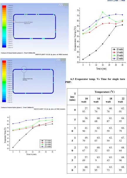
6.3 Evaporator temp. Vs Time for single turn PHP:
T ime (min)
Temperature (0C)
10 watt
14 watt
18 watt
22 watt
0 27.
83
58. 76
60. 76
62. 01
5 36.
86
60. 68
61. 87
64. 95
1 0
41. 96
62. 31
63. 59
66. 79
1 5
49. 79
63. 07
62. 59
67. 52
2 0
53. 67
60. 32
63. 03
68. 64
2 5
57. 69
63. 9
63. 43
68. 96
3 0
60. 20
61. 95
63. 73
68. 95
Table 6.8: 600 orientation - evaporator temp vs time for single turn PHP at 40% filling ratio
0 5 10 15 20 25 30
25 30 35 40 45 50 55 60 65 70
E
vapor
at
or
T
em
p (
0C)
Time in (min)
10 watts 14 watts 18 watts 22 watts
T ime (min)
Temperature (0C)
10 watt
14 watt
18 watt
22 watt
0 27.
48
55. 62
60. 13
60. 71
5 39.
59
58. 13
61. 32
62. 54
1 0
45. 79
60. 20
62. 07
64. 0
1 5
50. 71
60. 37
61. 08
64. 96
2 0
55. 70
60. 03
62. 2
65. 12
2 5
59. 95
61. 02
63. 51
68. 18
3 0
60. 39
62. 29
64. 7
68. 81
0 5 10 15 20 25 30
25 30 35 40 45 50 55 60 65 70
E
v
apor
at
or
T
em
p (
0C)
Time in (min)
10 watts 14 watts 18 watts 22 watts
Fig.6.7:300-evaporator temp vs time for single
Fig.6.8:600-evaporator temp vs time for single
turn PHP at 30% filling ratio turn PHP at 40% filling ratio
0 5 10 15 20 25 30
25 30 35 40 45 50 55 60 65 70
E
vapor
at
or
T
em
p (
0C)
Time in (min)
10 watts 14 watts 18 watts 22 watts
Fig.6.1 to 6.9 shows the variation of evaporator wall temperature with respect to time for 30%, 40%&50%filling ratio and300, 600 & 900. It is evident from the experiments that, there is a continuous pressure pulsation during the flow in a PHP. Thus the temperature readings are recorded when the movement of the working fluid starts. The steady state evaporator temperature versus time-curve is almost linear. It is also clear that the fluctuations in the evaporator temperature are more at higher heat input of 22 W due to intermittent motion of the working fluid and takes more time to reach the steady State.
2.
REFERENCES
1. Tahanee Muzib Fahim Ahmed and Chowdhery Md. Feroz -Fluidic Characteristic and Comparative Study with Single Phase Thermosyphon”, Proceeding of 12th international heat transfer conference, vol.4, pp.459-464, Grenoble, France, 2002.
2. Piyanum, Khandekar, s. Charoensawan, P. Groll, M. and Terdtoon, P., “Closed Loop Pulsating Heat Pipes, Par-B: Visualisation and Semi Empirical Modelling”, Applied Thermal Engineering, vol.23No.16, 2003, pp.2021-2033.
3. Shafii, B. M Faghri, A. Zhang, Y., ’Thermal Modelling Of Unlooped Pulsating Heat Pipes”, ASME J, Heat Transfer, vol.123No.6, 2001, pp.1159-1172.
4. Zhang, X. M. Xu, Zhou, Z. Q.,”Experimental Study of Pulsating Heat Pipe Using FC-72, Ethanol and Water as Working Fluids”, Experimental heat transfer, Vol.17, 2004, pp47-67.
5. Khandekar, S., “Multiple Quasi- Steady States in a Closed Loop Pulsating Heat Pipe”, NTUS-IITK 2nd joint workshop in
mechanical, Aerospace and Industrial Engineering, April 5-6, 2008 IIT Kanpur, India.