International Journal of Emerging Technology and Advanced Engineering
Website: www.ijetae.com (ISSN 2250-2459, Volume 2, Issue 5, May 2012)145
FUZZY SPEED CONTROLLER DESIGN OF THREE PHASE
INDUCTION MOTOR
Divya Rai
1,Swati Sharma
2, Vijay Bhuria
31,2 P.G.Student, 3 Assistant Professor Department of Electrical Engineering, Madhav institute of technology and
science,Gwalior.
1[email protected] 2[email protected]
Abstract— The induction motor is without doubt the most used electrical motor because of its unique characteristics. Most of its applications need fast and intelligent speed control system.This paper presents an intelligent and advanced speed control based on fuzzy logic technique to achieve maximum torque and efficiency.A rule based Mamdani type fuzzy logic controller is applied to closed loop induction motor
model.Scalar control(volt-hertz) method is used for
controlling speed.A conventional controller is compared practically to fuzzy logic controller using Matlab/Simulink software package.The simulation results show the superiority of the fuzzy logic controller.
Keywords — fuzzylogic, Inductionmotor, scalarcontrol, imulink, speed control.
I. INTRODUCTION
The induction motor is considered since its discovery as actuator privileged in the applications of constant speed, and it has many advantages, such as low cost, high efficiency, good self starting, its simplicity of design, the absence of the collector brooms system, and a small inertia. However, induction motor has disadvantages, such as complex, nonlinear, and multivariable of mathematical model of induction motor, and the induction motor is not
inherently capable of providing variable speed
operation.These limitations can be solved through the use of smart motor controllers and adjustable speed controllers [1]. Advanced control based on artificial intelligence technique is called intelligent control[2]. The fuzzy logic controller is the most efficient controller because of it’s non-linearity handling features and it is independent of plant model.
The technique to embody human-like thinking into a control system is fuzzy control. A fuzzy controller can be designed to emulate human deductive thinking, that is, the process people use to infer conclusions from their knowledge. Fuzzy control has been primarily applied to the control of processes through linguistic descriptions. Fuzzy logic control system consists of four blocks as shown in Figure 1.[2]
Figure1.Fuzzy control system
II. DYNAMIC MODEL OF INDUCTION MOTOR [3]
International Journal of Emerging Technology and Advanced Engineering
Website: www.ijetae.com (ISSN 2250-2459, Volume 2, Issue 5, May 2012)146
III. PROPOSED CONTROL SYSTEM
Due to poor dynamic performance in open-loop of induction motor, scalar control technique has been used in many applications to achieve high dynamic performance, get tracking speed, and generate maximum torque of induction motor.
A. Scalar Control
Scalar control as the name indicates, is due to magnitude variation of the control variables only, and disregards the coupling effect in the machine. Scalar control has been widely used in industry, the fact that they are easy to implement. The scalar control strategy is based on simplified volts/Hertz control scheme with stator frequency regulation as shown in figure2.
As the controller generates the slip speed ωsl signal that is added with electrical speed that yields synchronous speed ωs that is used in induction motor model with synchronous reference frame and generate the voltage command through Volts/HZ function to keep flux constant.[4]
Figure2.Block diagram of scalar control system B. Fuzzy-PI Controller
The fuzzy controller is basically an input/ output static non-linear mapping, the controller action can be written in the form [ 6 ]:
u = ke .e + k ce .ce The Fuzzy-PI output is:
y = k p .u + ∫ k i .u
Where ke is the gain of the speed error, kce is the gain of the change of speed error, kp is the proportional factor; ki is the integral factor, e is the speed error, ce is the change of speed error, u is the fuzzy output.
Figure3.Fuzzy PI control
IV. FUZZY LOGIC CONTROLLER
International Journal of Emerging Technology and Advanced Engineering
Website: www.ijetae.com (ISSN 2250-2459, Volume 2, Issue 5, May 2012)147 The membership function (MF) of the associated input and output linguistic variables is generally predefined on a common universe of discourse. For the successful design of FLC’s proper selection of input and output scaling factors (gains) or tuning of the other controller parameters are crucial jobs, which in many cases are done through trial and error to achieve the best possible control performance[1].
The structure of FLC is shown in figure4. The structure shows four functions,each one materialized by block : • A fuzzification interface, the fuzzy control initially converts the crisp error and its rate of change in displacement into fuzzy variables; then they are mapped into linguistic labels. Membership functions are defined within the normalized range (-1, 1), and associated with each label: NB (Negative Big), NS (Negative Small), ZE (Zero), PS (Positive Small), and PB (Positive Big). Five MFs are chosen for e(pu) and ce(pu) signals and five for output. All the MFs are symmetrical for positive and negative values of the variables. Thus, maximum 5х5 = 25 rules can be formed as tabulated in Table I.
Figure4. STRUCTURE OF FUZZY CONTROL
• A knowledge base (a set of If-Then rules), which contains the definition of the fuzzy subsets, their membership functions, their universe discourse and the whole of the rules of inference to achieve good control.
• An inference mechanism (also called an “inference engine” or “fuzzy inference” module), which is heart of a fuzzy control, poses the capacity to feign the human decisions and emulates the expert’s decision making in interpreting and applying knowledge about how best to control the plant.
• A defuzzification interface, which converts the conclusions of the inference mechanism into actual inputs for the process. In this work; Center Of Area (COA) is used as a deffuzification method, which can be presented as:
The gains G1, G2, and G3 are scaling factors to adapt the variables to the normalized scale. However, the inference strategy is the mamdani algorithm, so the if-then rules for fuzzy scalar control for speed control will be twenty five rules.
(a)
(b)
(c)
International Journal of Emerging Technology and Advanced Engineering
Website: www.ijetae.com (ISSN 2250-2459, Volume 2, Issue 5, May 2012)148
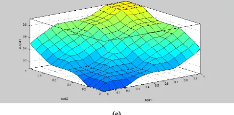
(e)
Figure5. (a,b)Inputs membership function, (c)Output membership function, (d) Rules view (e)Surface view.
TABLE I
RULES FOR FUZZY CONTROLLER
Δe NB NS ZE PS PB
e O/P
NB NB NB NS NS ZE
NS NB NS NS ZE PS
ZE NS NS ZE PS PS
PS NS ZE PS PB PB
[image:4.612.49.288.135.253.2]PB ZE PS PS PB PB
TABLE II
.PARAMETERS OF INDUCTION MACHINE[5]
Parameters Symbols Values units
Shaft power P 2.2 kw
Number of pole pairs P 2
Stator resistance Rs 2.4 Ω
Rotor resistance Rr 1.452 Ω
Total leakage factor σ 0.136
Mutual inductance M 0.1 H
Stator(rotor) self inductance Ls=Lr 0.121 H
Inertia moment J 0.013 SI
Viscous friction coefficient f 0.002 SI
TABLE III
COMPARED WITH CONVENTIONAL SPEED CONTROL APPLIED ON 3 PHASE,415V,3HP INDUCTION MOTOR(Drum
size d=.225m)
S . N o
Line Voltage (in volts)
Input curren t(in amper es)
W1
Input W2
Inp ut
Loa dS1
Loa d S2
(in Kg)
Speed Nr(in RPM)
1 360 1 360 40 0 0 1500
2 356 1.25 460 240 0 2 1460
3 355 1.5 680 320 0 4 1455
4 354 2 880 400 0 6 1436
5 350 2.5 1040 520 0 8 1424
6 344 3 1120 640 0 10 1414
7 340 3.5 1320 740 0 12 1400
8 335 4.2 1560 920 0 14 1385
MODEL OF INDUCTION MOTOR IN SIMULINK [6]
Figure6. Fuzzy scalar speed control of induction motor in Matlab/simulink
V. SIMULATION RESULTS
Simulation results have been realized under
[image:4.612.47.289.421.656.2]International Journal of Emerging Technology and Advanced Engineering
Website: www.ijetae.com (ISSN 2250-2459, Volume 2, Issue 5, May 2012)149
VI. CONCLUSIONS
Fuzzy logic controller shows fast control response with induction motor.This controller gives maximum torque over the entire speed range.Linguistic rules control the speed.This speed controller shows fast response,smooth performance and high dynamic response with changing and transient conditions.
REFERENCES
[1 ] Fuzzy Controller for Three Phase Induction Motor Drives by Basem M. Badr,Ali M.Eltamaly and A.I.Alolah.
[2 ] Induction Motor Speed Control using Fuzzy Logic Controller by V.Chitra and R.S.Prabhakar,World Academy of Science,Engineering and Technology 23,2006.
[3 ] Speed Control of Induction Motor using Fuzzy-PI Controller by Divya Asija,IEEE 2010,2nd International Conference on Mechanical and Electronics Engineering(ICMEE2010),vol.2,pp.460-463. [4 ] B.K.Bose,Modern Power Electronics and AC
Drives,Prentice-Hall,Upper Saddle River,NJ,2002.
[5 ] Fuzzy Logic Speed Control Algorithm of Induction Motor Fed by
Direct Matrix Converter by F.Tazerart and P.Le
Moigne,International Journal of Research and Reviews in Computer Engineering,vol.1,No.1,March 2011.
[6 ] Scalar Speed Control of a dq Induction Motor model using Fuzzy Logic Controller by Ramon C.Oros,Guillermo O.Fortr,Luis Canali. [7 ] Modeling & Simulation using Matlab® -Simulink® by Dr.
Shailendra Jain,First Edition :2011.
[8 ] Leonhard Werner,Control of Electrical Drives,Third edition Springer-Verlag.Berlin(2001).
[9 ] Mohan N.,Advanced Electrical Drives Analysis Control and Modeling Using Simulink,MNPERE.Minnesota(2001).