2019 International Conference on Computer Science, Communications and Multimedia Engineering (CSCME 2019) ISBN: 978-1-60595-650-3
Research on Image Navigation Algorithms for UAV
Bai ZHANG, Cai-ying WEI and Rui-ting GE
School of Electrical Information Engineering, North Minzu University, 750021, China
Keywords: Perspective transformation, Threshold segmentation, ROI, OpenCV.
Abstract. UAV (unmanned aerial vehicle) is used in agriculture filed to inspect water conservancy facilities, it not only can greatly reduce labor, but also effectively save relevant costs. The choice of UAV navigation mode is the key problem to achieve patrol of water conservancy facilities. In order to solve this problem, a new method of UAV image navigation is proposed which is different from traditional image navigation, and experimental research is carried out. Firstly, the acquired image is corrected and preprocessed to reduce image noise by perspective transformation. Then, the target information is extracted by threshold segmentation and ROI (region of interest) method. Finally, the attitude information of UAV is calculated and displayed in the original image through OpenCV (Open Source Computer Vision Library) library function. Based on the calculation results, the attitude of UAV can be adjusted by flight controller.
Introduction
Image processing and tracking technology has been used in military since 1960 [1]. Originally, two-dimensional annotation projection method was used to realize navigation, but there are some errors of sensor localization, which makes navigation to be inaccurate. Then a navigation method based on feature matching was proposed. In recent years, intelligent image navigation system based on neural network has gradually emerged. With the development of computer hardware, image navigation technology is more and more widely used in various fields, such as robot vision navigation and medical surgery.
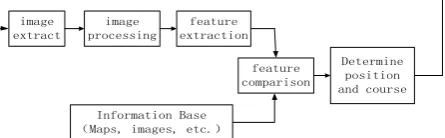
Traditional image navigation is to use airborne sensors to obtain flight information of UAV, and the acquired images are processed and analyzed to identify the important information in the pictures. The accurate position and height of UAV are determined by comparing the original information with the information obtained from image processing. The implementation process of image navigation technology is shown in figure 1.
image extract
image processing
feature extraction
feature comparison
Information Base (Maps, images, etc.)
[image:1.595.190.413.531.600.2]Determine position and course
Figure 1. Implementation of traditional image navigation.
Three main traditional image navigation methods are used in image navigation field. First method, it is according to the specific scenery to achieve navigation [2], this method is to determine the position of UAV by the position of specific scenery, where scenery refers to human scenery and natural scenery, such as rivers, tall buildings, man-made navigation aids, etc. Second method, it is according to feature matching to realize navigation [3], which determines whether the UAV enters target area or approaches target area by feature matching. Generally, roads are used as reference. Third method, it uses topographic map matching to realize navigation, this method determine the position of the UAV by comparing the features of the topographic map stored in the system in advance with the captured image, but this method requires a larger storage space for the system of UAV.
characteristic sceneries, and the UAV does not have large storage capacity. For this reason, three image navigation methods mentioned above are not optimal. A set of new methods are proposed to realize image navigation by image correction, ROI interception, perspective transformation, image processing, feature extraction and other methods in this paper.
Design and Experiment of Image Navigation Algorithm
Overall Design of Algorithm
The algorithm flow chart of pipeline identification and processing is shown in figure 2.
Image reading
Information
display Calculation
Pipeline identification
Perspective transform
Platform removal Threshold
segmentation Distortion
correction
Figure 2. The algorithm flow chart of pipeline identification and processing.
Distortion Correction Principle and Experimental Results
The essence of camera imaging process is the transformation between four coordinate systems, which are world coordinate system, camera coordinate system, image coordinate system and pixel coordinate system. In the imaging process, firstly, the point in the world coordinate system is transformed into the camera coordinate system by translation and rotation. Secondly the camera coordinate is projected into the image coordinate system. Finally, the image coordinate system is transformed into the pixel coordinate system. During transformation process, because of the hardware manufacturing technology and other reasons, the straight line is no longer a straight line after transformation. It leads to image distortion. Distortion is more obvious in imaging system of short focal length. In order to take full picture of the scenery in UAV aerial photography process, short focal length or wide angle lens are chosen in this paper.
In the design of algorithm, the camera calibration matrix and distortion coefficients are calculated by using methods which are provided in OpenCV library, and then the distortion correction is realized. The steps are as follows.
Firstly, the Z axis of the world coordinates is set to zero, so that the chessboard is on the XOY plane. For each picture of the chessboard picture group, the corresponding world coordinates are the same. The object points of the inner corner of the chessboard and the corresponding image points should be obtained. The image coordinates of the inner corner of the picture can be obtained by Find Chessboard Corners function from OpenCV library.
Second, the camera calibration matrix and distortion coefficients are calculated by the method of calibrate Camera function from OpenCV library with parameters the world coordinates and image coordinates of the chessboard.
Third, the corrected image can be obtained by using cv2.undistort function. The corrected figures is shown in figures 3.
Figure 3. The picture after correction.
Threshold Segmentation Principle and Experimental Comparison
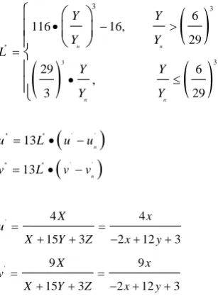
Conversion process from RGB to LUV includes conversion from RGB to CIE XYZ and conversion from CIE XYZ to LUV. The specific conversion formulas are shown in formula 1 to 4[5].
Conversion formula from RGB to CIE XYZ is show in 1.
11 12 13
21 21 22 23
31 32 33
0.49 0.31 0.20 1
0.17697 0.81240 0.01063 0.17697
0.00 0.01 0.99
b b b
X R R
Y b b b b G G
Z b b b B B
(1) Conversion formula from CIE XYZ to CIE LUV is show in 2 to 4.
* 3 3 3 3 6 116 16, 29 29 6 , 3 29 n n n n Y Y Y Y L Y Y Y Y (2)
* * ' ' * * ' ' 13 13 n nu L u u
v L v v
(3) ' ' 4 4
15 3 2 12 3
9 9
15 3 2 12 3
X x
u
X Y Z x y
X x
v
X Y Z x y
(4)
' '
, ,
n n n
Y U V
is the value of standard white.
Experimental Comparison. Edge detection and threshold segmentation are classical image segmentation methods [6]. Edge detection is used to process the image. Compared with the other three edge detection operators, the edge image obtained by Canny operator is better. There are two main reasons. First, it can make full use of the direction of edge gradient. Second, it can use double threshold lag threshold processing [7]. Figure 4 is the experimental results obtained respectively by Canny operator.
[image:3.595.74.228.214.423.2]
Figure 4. Edge detection by Canny operator.
[image:3.595.249.347.530.611.2]
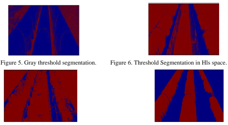
Figure 5. Gray threshold segmentation. Figure 6. Threshold Segmentation in Hls space.
Figure 7. Threshold Segmentation in lab space. Figure 8. Threshold Segmentation in Luv space.
Four pairs of pictures are processed by four different thresholding methods. Figure 5 is the result obtained by directly transforming the color image into gray image and then thresholding. Figure 6 to 8 is transformation results from the RGB color space into HLS, LAB and LUV respectively, and then appropriate thresholds are used to segment the image. The conclusion can be obtained that four pictures that the background processing of the images in figure 5, 6 and 7 is Unsatisfied, and the boundary between the pipeline and the background cannot be clearly distinguished in the picture, which will bring great difficulties to the subsequent pipeline recognition.
Platform Elimination Method and Experimental Results
Platform Elimination Method. Pictures are processed by threshold to get binary images with only pipeline and background. In binary images, the color of platform and pipeline is the same, so the platform will affect the subsequent pipeline recognition. The method of platform process is to use ROI method to intercept the platform directly after meeting the platform, so that it will not appear in pipeline detection. The method of eliminating platform is that statistical the number of white pixels corresponding to each height h by histogram [8]. When the white pixel values corresponding to a certain height accumulate and are higher or lower than a certain threshold value, it must be the platform part. A large experimental results show that the threshold value is 2000 when the platform is bottom of picture, and the threshold value is 500 when the platform is top of picture.
Experimental Results. The results of the above algorithms are shown in figure 10 to 12.
[image:4.595.170.432.563.754.2]
Principle of Perspective Transformation and Experimental Results
Perspective transformation [6] is to project the original image to another new viewing plane, which is also known as projection transformation. The principle of perspective transformation is shown in formula 5[6].
11 12 13
21 22 23
31 32 33
11 12 13
21 22 23
31 32 33
a a a
X x
Y a a a y
Z a a a z
a a a
A a a a
a a a
(5) In the formula 5, x y z, , T is the coordinate of the point to be moved in the original image, and
X Y Z, , T is the coordinate of the selected target point in the target coordinate system. By choosing four
such points, the transformation matrix A can be obtained by simultaneous equation, and then the points in the original image can be transformed into the target plane by using the matrix A.
Because perspective transformation has a good feature which is keeping "straight line" [7], that means the straight line of the original image is still straight after perspective transformation. The design is mainly through perspective transformation to obtain a more intuitive perspective, which is in favor of the detection of straight lines.
Perspective transformation is used to transform the picture into bird's-eye view in this paper, which is in favor of pipeline identification. The experimental results are shown in figure 13 and 14.
[image:5.595.247.350.626.705.2]
Figure 13. Original Figure. Figure 14. The results of perspective transformation.
Calculation and Display of Deflection Angle
The calculation principle of deflection angle is shown in Figure 15. The green line represents the direction of UAV, the red line represents the direction of pipeline, and the points A, B, C and D represent the edge points of pipeline. When the flight direction of UAV deviates from the pipeline direction, the attitude and direction of UAV can be adjusted by calculating the specific deviation angle. The principle of deflection angle calculation is shown in formula 6 and figure 15.
Θ
A(x1,y1) B(x2,y2)
D(x4,y4) C(x3,y3)
Figure 15. The principle of deflection angle calculation.
3 1
3 1
= arctan x x
y y
The calculated angle is displayed in real time in the video, and the pipeline area detected by the bird's-eye View binary image is mosaic back to the original image by using the inverse deformation matrix to improve the brightness of the pipeline area. The effect is shown in figures 18, 19 and 21.
[image:6.595.173.425.119.425.2]
Figure 16. Original figure. Figure 17. Result figure.
Figure 18. Original figure. Figure 19. Result figure.
Figure 20. Original figure. Figure 21. Result figure.
Conclusion
The research and experiment for patrol of water conservancy facilities based on image navigation technology is introduced. The image navigation method proposed in this paper breaks through the limitations of traditional image navigation, and has no special requirements for the environment around patrol facilities and the storage equipment of UAV. It not only reduces the cost of patrol of water conservancy facilities, but also avoids the damage to patrolman caused by harsh environment in the field. Firstly, the method corrects and preprocesses image to reduce image noise. Then the target information is extracted by threshold segmentation and ROI method. Finally, the attitude information of UAV is calculated and displayed in the original image through OpenCV library function. The method proposed in this paper has wide application value, not only in the patrol of water facilities, but also in the field power lines and other patrol works.
Acknowledgment
This work was sponsored by the Major Science and Technology Projects of Key Research and Development Plan in Ningxia (2017BY067).
References
[3] Zhang Chengtao. Research on Algorithms for UAV Aerial Image Stitching[D]. Beijing Institute of Technology, 2015.
[4] Xu Haili, Hua Guoran, Zguang Jian, Wang Sun’an. A Frequency Domain Approach to Image Registration Using Small World Clonal Selection Algorithm [J]. Journal of Xi'an Jiaotong University, 2009, 43 (6): 38-42.
[5] Soisson O, Lube J, Germano A, et al. Pelvic belt effects on pelvic morphometry, muscle activity and body balance in patients with sacroiliac joint dysfunction. PLo S One. 2015.
[6] Jun Liu. Research on the Key Technology of Face Recognition[D]. Beijing University of posts and Telecommunications, 2015.
[7] M. Jourlin, J. C. Pinoli. Contrast definition and contour detection for logarithmic image. J .Microscopy. 1989.