Patterns in Data Conversion
Allard Muis May 2009
Master Thesis Computer Science University of Twente
Under supervision of:
University of Twente Dr. M.L. Ponisio Dr. P.A.T. van Eck
3
Abstract
When a legacy information system is replaced by a new information system, the data inside the legacy system needs to be moved to the new system. This process is called data conversion. In the data conversion the data is exported, transformed to fit the new systems data structure and imported in the new system.
Making a design for a data conversion is a complex and time consuming task. Designers feel the need to improve the efficiency of the design process. They would like to share and reuse experience of data conversion design in other projects. There is currently no structured way of doing this.
This thesis proposes the use of design patterns in data conversion design in order to enable designers to reuse experience. These data conversion patterns describe a common, recurring problem in data conversion design and give a solution to resolve the problem that has proven to work effectively in the past. Five data conversion patterns are provided.
The patterns are structured in a pattern language. This language groups patterns that give a solution for the same problem. Using this, a designer can quickly find multiple alternative solutions for a data conversion design problem. New patterns can easily be added to the pattern language.
A designer needs to decide which solution fits the context of a particular problem best. In order to make this decision easier, every pattern is weighted on eight quality attributes. Depending on the context and situation, a good score on some attributes is more important than others. The quality attributes also give very clear insight in the tradeoffs of a pattern.
The data conversion patterns were evaluated by a discussion with several experienced designers. They recognize the problems and solutions described in the patterns and support this solution for enabling reuse is data conversion design. Comments of the experts were used to improve the patterns further.
Data conversion patterns allow designers to share design experience with each other and reuse this experience in other projects. Using patterns designers can make better, explicit design decisions based on experience recorded in the past. This will lead to improved efficiency of the design process, resulting in better design while needing fewer resources.
5
Acknowledgements
6
Table of contents
Abstract ... 3
Acknowledgements ... 5
Table of contents ... 6
1. Introduction ... 9
1.1 Background ... 9
1.2 Problem statement ... 10
1.3 Research questions ... 11
1.4 Approach ... 11
1.5 Thesis structure ... 12
2. Data Conversion ... 15
2.1 System replacement ... 15
2.2 Data conversion ... 15
2.3 Structure of data conversion ... 16
2.4 Data conversion design ... 19
2.4.1 Data mapping ... 20
2.4.2 Conversion plan ... 22
2.5 Acceptance criteria ... 23
3. Data Conversion Patterns ... 25
3.1 Introduction ... 25
3.2 Data Conversion Patterns ... 26
3.2.1 Quality attributes ... 26
3.2.2 Pattern template ... 30
3.3 A pattern language ... 31
Problem 1: Different domains in source and target system ... 35
Legacy Records ... 37
Enlarge Domain ... 41
Map To Valid Value ... 44
Problem 2: Splitting a value ... 49
First Field Gets All ... 51
Split Field ... 55
4. Validation and Evaluation ... 59
4.1 Validation ... 59
4.2 Evaluation ... 60
4.2.1 Evaluation session ... 61
4.2.2 Expert opinions ... 62
4.2.3 Improvements after evaluation session ... 62
7
4.3 Functional Design Patterns ... 63
4.3.1 Domain and aspect level ... 64
4.3.2 Technical and implementation details ... 65
4.3.3 Incorporation in software development ... 65
4.3.4 Language of Functional Design Patterns ... 65
4.3.5 Conclusion on Functional Design Patterns ... 66
5. Conclusions ... 67
5.1 Research question ... 67
5.2 Main conclusion ... 68
5.3 Further conclusions... 68
5.4 Future research ... 70
9
Chapter 1
Introduction
1.1
Background
Data conversion is the act of moving data from one information system to another information system. Since two information systems are usually structured differently the data needs to be converted. The process of data conversion comprises three parts: exporting data from the source system, restructuring the data and importing the data in the target system. In this thesis, we will concentrate on the restructuring part of data conversion.
A data conversion cannot be done ad-hoc, but must be designed first. Such a design contains decisions about what data is moved where, how this data is restructured and how this can be executed. For systems that have a very elaborate datamodel (i.e. a large number of tables, columns and relations between them), like systems for insurance and banking organizations, designing the way the data is converted can be a time-consuming task.
A conversion designer needs to make a lot of design decisions. He comes across many problems that he needs to design a solution for. For example, every time a single field from the source system needs to be mapped to a single field in the target system, he needs to decide whether the value of the target field should be looked up in a table or that maybe an algorithmic function would be better. Or maybe still another way? The designer needs to find the up and downsides of each approach and judge which solution fits the situation best.
Another example of such an issue is the order in which entities are converted. Should we start with converting every insurance policy, and then all coverages of the policies? Or is it better to convert one policy, then convert all coverages that policy has and move on to the next policy and its coverages?
Later on in the design or in the next project, if the same situation occurs, the designer will need to think again about the possibilities and find the best solutions. While he could fall back on the way he solved it the previous time, it may not easily be recognizable as a similar case. It may not be obvious to the designer that he is solving the same thing again. Even if he notices, a slightly different situation calls for a new evaluation of the possible solutions.
10
The concept of design experience is difficult to define. According to WordNet Online (WNO), experience is “the accumulation of knowledge or skill that results from direct participation in events or activities”. Data conversion design experience is thus the knowledge and skills you learn from creating data conversion designs. Documenting such experience in order not to forget and share it with other designers is important but difficult.
Design patterns have emerged over the last decade as a good way to reuse solutions and design experience. Many different types of patterns have been described to enable reuse at different places and at different levels of abstraction. Examples are technical design patterns (GHJV95)(YA04), user interface design patterns (WVE00), analysis patterns (Fow97)(Fow02) and functional design patterns (Sni04).
The research reported in this thesis has partly been performed at Quinity B.V. Quinity is a company that develops e-business solutions and information systems. For the largest part, these systems are administrative applications for insurance companies in the Netherlands. Such systems have large databases containing customer information, insurance policies and claims. When a new application is delivered, the data from the old, obsolete system must be converted. Having done many of such projects, Quinity has considerable experience in data conversion.
Quinity already reuses design experience in the design of new systems. Functional Design Patterns (Sni04) are used in the functional design in order to reuse functionality such as workflows and time dependent information. Technical design patterns from Gamma et. al. (GHJV95), among others, are used in the technical design. During implementation, reuse is stimulated with a framework and standard components. Because of their experience with reuse through patterns, Quinity engineers noted that in practice there is currently no good way of reuse in data conversion design.
1.2
Problem statement
Making a design for a data conversion project is often complex, expensive and time consuming. This does not mean that designers are unable to make quality conversion designs but that they feel the need for improved efficiency, in order to make good designs using fewer resources or better designs with the available resources.
Researchers are acknowledging this need for improved efficiency for a long time already and research into this topic goes back as far as the 1970s. Shu, Housel and Lum (SHL75) defined the languages „DEFINE‟, which can be used to describe data structures and „CONVERT‟, which can describe the mapping between two data structures. These two languages were intended to serve as a means to specify a data conversion. A little more recently, Cluet et al. (CDSS98) presented the language „YATL‟ which has a similar goal but is better suited for modern relational databases. Languages like „CONVERT‟ and „YATL‟ enable a designer to effectively specify a data conversion design and communicate this to other stakeholders.
11
to target system using a graphical editor. Graphical data mapping is also possible with MapForce (ALT) which supports converting data from and to a wide variety of data sources.
The field of data warehousing is related to data conversion. Data warehouses are used to store and analyze vast amounts of data from different sources. Data coming from these different sources needs to be transformed in order to be combined and stored (SV08). While a data conversion project is a one-time transformation and a data warehouse continuously receives and transforms data, the transformation is similar. Data warehousing is supported by ETL (extraction, transformation, loading) tools. Vassiliadis et al. summarize the tasks of ETL tools: identifying and extracting data from source systems, integrating the data from multiple sources into a common data format, cleaning the data and loading the result into the data warehouse (VVS+01). Deciding what data should be combined and what transformations should be applied on the data still needs to be done by a human designer.
Each of these approaches can indeed increase efficiency of data conversion design. At the same time, there is still room for improvement as none of these approaches enables designers to reuse and share design experience they gained in the past. Therefore, the problem statement of this research is:
“It is currently only possible to reuse design experience of data conversion in an ad-hoc, suboptimal way. There is no structured, effective way to reuse design experience.”
1.3
Research questions
The problem statement leads to the following main research question:
“How can we improve the efficiency of making data conversion design?”
In order to construct an answer to this we need to research the following questions:
- What criteria should the solution meet for it to indeed increase efficiency?
- What are the elements of a data conversion design?
- How should data conversion design experience be documented?
- What design experience is available and can be recorded?
1.4
Approach
12
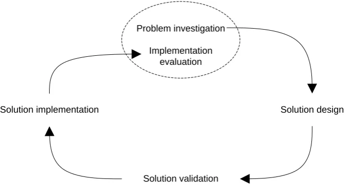
The engineering cycle, shown in figure 1.1, is a well known way of solving a design problem. In this thesis we will use the engineering cycle as the approach in solving the problem statement. The first step of the engineering cycle is the problem investigation. In this step we analyze the problem discussed in section 1.2 and make a list of acceptance criteria which the solution should meet. If a solution does not satisfy these criteria (to a certain extend), it does not really solve the problem at hand.
In the second step, the solution design, we design a solution to the problem. This design is validated in the third step, solution validation. Here the design of the solution is compared to the acceptance criteria and we check to what extend the solution satisfies these criteria.
In the fourth step the solution is implemented: “realized and placed in its use environment” (PER08). Using the solution proposed in this thesis and starting to reuse design experience is outside the scope of this research. Therefore, solution implementation is not part of this thesis.
The engineering cycle closes with the evaluation of the solution. Does it really solve the problem as intended? What new issues arise within the altered state of the world? We will investigate such questions in the last part of the thesis.
Solution design
Solution validation Solution implementation
Problem investigation Implementation
[image:12.595.117.464.346.532.2]evaluation
Figure 1.1: Engineering cycle (adapted from (PER08) and (Wie07))
1.5
Thesis structure
This thesis is structured in five chapters. The following chapters contain the results of each of the steps of the engineering cycle.
13
Chapter 3 describes the proposed solution. We discuss how we can most effectively document data conversion design experience. Based on discussions with designers and design documentation we propose a library of design experience that can be reused.
In Chapter 4 we validate and evaluate the proposed solution. We ask ourselves whether the solution proposed in chapter 3 matches the acceptance criteria of chapter 2 and we discuss the solution with data conversion designers.
15
Chapter 2
Data Conversion
This chapter explores data conversion in more detail. We look at when you need data conversion, what data conversion looks like, the phases a data conversion project consists of and the design of data conversion.
2.1
System replacement
Many companies are using old information systems to support their business processes. These systems were designed and created with technology that may have been state of the art at that time, but is now obsolete. Systems like this are often called legacy systems. Brodie and Stonebraker (BS95) define a legacy system as “any information system that significantly resists modification and evolution”.
Data conversion is necessary when an organization decides to replace a legacy system with a new information system. While developing a new system is expensive, maintaining a legacy system may be even more expensive in the long run (Vis01, BCV03). It is increasingly hard to find personnel with the necessary skills in the aging techniques and it is very hard to evolve the information system to keep supporting the changing needs of the business processes. Replacement is a good opportunity to implement new functionality that was not supported by the legacy system.
Replacing it is not the only technique to cope with the challenges of legacy systems (Ben95). For example, encapsulating a legacy system with modern technology can be a useful and less expensive technique. There is no need for data conversion in this case because the data remains in its original database.
2.2
Data conversion
16
Design Section 2.4 Structure Section 2.3
Data conversion
Export Transformation Import
Functional Design Technical Design
[image:16.595.72.531.81.329.2]Data mapping Conversion plan
Figure 2.1: Data conversion aspects
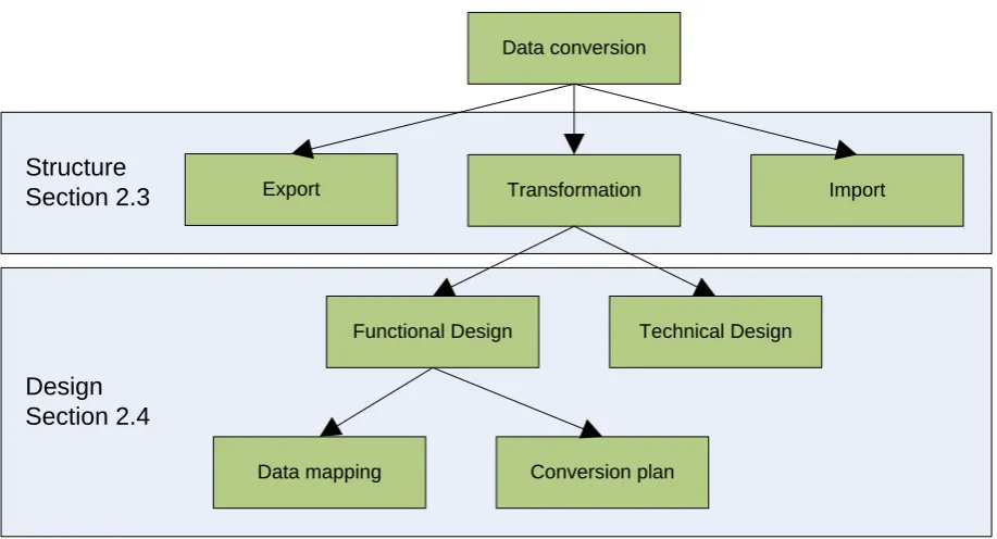
Figure 2.1 gives an overview of the aspects of data conversion. It is divided in two parts: structure and design. The structure of data conversion will be discussed in section 2.3 while the design of data conversion is the subject of section 2.4. Not all parts shown in the picture are analyzed equally thoroughly, the focus lies on the parts that are candidates of reusing design experience.
Data conversion is possible between any two information systems. As long as there is data in one system you can convert it to another system, it does not matter what kind storage technology the system employs. Very old legacy systems are still using text-file based storage systems, while XML and object based technology is on the rise. The majority of information systems are built on a relational database, however, and it looks like relational databases will be the dominant force for some time at least. Therefore, we will be focusing on relational databases in this thesis.
2.3
Structure of data conversion
17
Source system
Logic
Database
Target system
Logic
[image:17.595.169.427.81.275.2]Database Data conversion
Figure 2.2: Data conversion
Data conversion does not concern the design or creation of any part of the target system, just the conversion of the data itself from the source system to the target system.
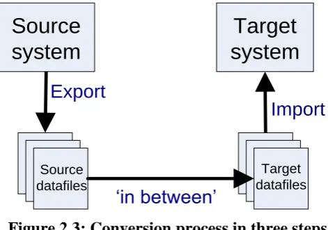
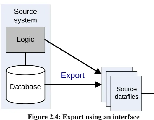
Conversion is done in multiple steps. First, the data is exported from the database to a set of datafiles. These files can then be used exclusively by the conversion. The source datafiles are then converted to the target datafiles in an „in between‟ step. Finally, the resulting target datafiles are imported in the database of the target system. Figure 2.3 shows this process. In each of these three steps part of the conversion can be performed. Some types of operation are best done in one of the three steps. For example, removal of redundant information is best done during the „export‟ step, while introducing new redundancy in the target system should be done in the „import‟ step.
Source datafiles
Export
Import
‘in between’
Target
system
Source
system
Target datafiles
Figure 2.3: Conversion process in three steps
[image:17.595.177.413.438.603.2]18
Source datafiles
Export
Sourcesystem
Logic
[image:18.595.156.417.81.284.2]Database
Figure 2.4: Export using an interface
Such an interface can be used for the target system as well. Data from the target datafiles can be imported through the logic of the target system or to its database directly, as can be seen in figure 2.5.
Import
Target datafiles
Target system
Logic
[image:18.595.181.433.340.528.2]Database
Figure 2.5: Import using an interface
It is not necessary to do the „in between‟ step at once. The step can be divided in multiple smaller steps. The intermediate results are stored in intermediate datafiles that are converted further to the target datafiles. An example of this process with one intermediate step is shown in figure 2.6.
Source datafiles
Target datafiles Intermediate
files
‘in between’
[image:18.595.125.471.611.722.2]19
2.4
Data conversion design
According to Purba‟s Data Management Handbook (Pur99), a data conversion project is comprised of several phases. After these phases have been discussed, we will look how they relate to the design of data conversion.
1. Determining if conversion is required
In some cases, Purba claims, conversion is not required because the data is available at other locations. The data may also have such a low quality, i.e. much erroneous or missing information, that conversion is not worth its cost.
2. Analysis of source datamodel
This step should give the developer understanding of the source systems‟ data model. When there is very limited documentation about the system available and the systems‟ owner can provide only limited information, this step can be difficult and time consuming. But without a good understanding of the datamodel and the meaning of the data, it can never be successfully converted to the target system.
3. Investigating data quality
It is important to know whether the data is consistent with the datamodel. Inconsistencies will lead to problems during the conversion or a lot of data that cannot be converted automatically. For example, many legacy systems make extensive use of free text fields. Users of the systems often abuse these fields to store other data than the field was intended for. By investigating the quality of the data an estimation of these problems can be made.
4. Analysis of target datamodel
The developers of the conversion also need to understand the datamodel of the target system. The target system is often better documented than the source system as it is brand new. This analysis is therefore not as difficult as the analysis of the source system.
5. Determining the data mapping
When the developers understand both the source and target datamodel they can design the mapping between the models. This mapping specifies for each field in the target datafile from what field in the source datafile the data must be taken. Often, this involves difficult steps where fields are filled depending on the value of other fields, where data from a single field must be split to multiple other fields or where the value of a field in the target datafile depends on the values of many fields in the source datafile. A lot of research has been done into data quality and data cleaning in the field of data warehousing, for example see Rahm and Do (RD00).
6. Determining how to treat missing information
20 7. Programming the conversion
When it is decided how to convert the data from the source to the target system, software to execute the conversion must be written and tested.
8. Running the conversion
When the conversion program is created, it must be executed. This will actually fill the target datafiles.
9. Verifying conversion
When the conversion is finished, it is important to verify that all data is indeed converted. For example, it could be unacceptable to have „forgotten‟ to convert a few customers. So it must be ensured that the target database contains all data, and that all data is correct.
There are two forms of design of data conversion: functional design and technical design. The functional design of data conversion describes all the issues concerning the conversion on a conceptual level. This design discusses the result of phases two to six: analysis of source and target data models, investigation of data quality, the mapping of the data and the way missing information is treated. It also determines what data is converted and what not. For example, it may be decided not to convert customer information that is over ten years old as there is no purpose for this information anymore.
While all the parts of the functional design have their own problems and difficulties, designers especially recognize the data mapping (step 5) as a place where they encounter many reoccurring problems. This leads us to believe that this is the place where documenting and reusing design experience would be the most efficient. Therefore, we will concentrate on data mapping problems for the rest of the thesis. Research on reuse of design experience of other phases, for example determining how to treat missing information, may very well be worthwhile but is outside the scope of this thesis and is considered future research.
The technical design concerns the technical issues of the data conversion and contains the design for the phases seven, eight and nine. Technical design has a lot in common with technical design of „normal‟ software. Reuse of technical design experience has been studied at length (see for example (GHJV95)) and will not be discussed further in this thesis.
2.4.1
Data mapping
The data mapping is part of the functional description of the conversion. It describes which fields or entities in the source system are converted to which fields or entities in the target system and what transformations are applied to this data. The way this is described varies according to how detailed the conversion designers need to document the mapping. For example, it can be done in a large table, where for every field in the target system is recorded from which fields in the source system it is taken or what formulas are used to calculate its value. It also can be done in a textual, less formal fashion: “the age of the customer is calculated using the current date and the date of birth in the source system”.
21
is present in the source system. In this thesis we will call this way the „push‟ method, since data is pushed out of the source system to the target system. The push method describes for one or more fields in the source system to what fields in the target system the data is moved. Using this way, it is easier to verify that all data that is present in the source system is converted to the target system.
In the second case the mapping describes how the fields in the target system are filled. From now on we will call this the „pull‟ method. The pull method describes for one or more fields in the target system what fields in the source system are used to fill these target fields. The pull method makes it easier to verify that all fields in the target system are filled.
In a single conversion design, both pull and push methods can be used. The entire mapping does not have to be described using the same method. For some fields it may be better to use the pull method while for other parts it is better to use the push method. When the push method is used for every field in the source system and the pull system is used for every field in the target system, one can ensure that all data from the source system is being converted and all fields in the target system are filled, i.e. the conversion is complete. Because completeness is an important aspect of data conversion, it is good practice to describe the conversion using both push and pull methods. However, the descriptions need to be consistent and should not contradict each other. Without tool support it may be difficult to guarantee this consistency.
The data mapping consists of a lot of small parts each describing how one or a few fields are mapped. Sometimes it is useful to describe the conversion of multiple fields at the same time, but if you describe too many fields at once it will become difficult to comprehend. These mappings are described in either the push or pull fashion. Each description has one of the following cardinalities.
One to one
A single field in the source system is converted to a single field in the target system. This is a very simple case, although a complicated transformation may be used to convert the value of this source field to the target field.
One to many
A single field in the source system is converted to multiple fields in the target system. In this case the value of this single source field solely determines the value of multiple fields in the target system. This is often the case when certain data that is stored in a single field in the source system is split over multiple fields. For example, the source system may store an address in a single field, while the target system uses two fields, one for the street name and one for the house number. Such a mapping is best described using the push method since it describes how to fill multiple fields using a single source field. A one to many cardinality can be used to split non-atomic data into multiple atomic values.
Many to one
22
stores the address in a single field. But it can also be more complicated, for example when someone‟s age, gender and address are used to calculate the risk category someone is in for determining an insurance premium. Mappings with this cardinality are best described using the pull method.
Many to many
Multiple fields from the source system are converted to multiple fields in the target system. This is the most complicated case where in both the source system and the target system multiple fields are used in a single data mapping.
In most cases it is possible to split the „many to many‟ mapping in multiple „many to one‟ mappings as these are easier to understand. Sometimes, for example when multiple fields are used in a calculation which result must be stored in multiple target fields, splitting is not possible or leads to the same complex calculation being done multiple times.
Zero to one
The target system may have fields that store data that was not stored in the source system. This data is not really converted, but something has to be filled in in these target fields. Often this will be simply dummies or default values but it needs to be described in the design of the data conversion. While this case can hardly be called a mapping, it is natural to describe it in the same place. This cardinality can only be described in a pull method as no source fields are being used.
One to zero
A one to zero mapping effectively means the data from the source system is not converted to the target system. It can be useful to include such a description to make it clear it was a conscious decision not to convert the data. Clearly, only the push method can be used for describing data that is not taken to the target system.
2.4.2
Conversion plan
The data mapping describes what source fields are used to fill the target fields. But in reality only one piece of data can be read from the source datafiles and copied to the target datafiles at a time: actually converting the data is a sequential process.
We call the way this sequential process is executed the „conversion plan‟. The design of this plan concerns the order in which fields in the source system are read, when new records in the target system are created and when data is written to those records. So the conversion plan describes how the data mapping can be executed.
23
find in the source table we create a new record in the insurances table in the target system. We look up the customer it belongs to and link the policy to that customer. Policies in the target system have a reference to its latest version; we leave that empty for now. Then we read the table holding the policy versions. For every policy version we create a new record in the versions table in the target system. We look up the policy it belongs to and link the version to that policy. When all policy versions are converted we create a reference from the policies to their latest version.”
There are a few difficult issues regarding the conversion plan. The first is dealing with references between entities, i.e. the foreign keys in the database tables. Primary keys are usually not converted from the source system to the target system. When a record in the target system is created, a new key is made in the form of a unique id. This means that foreign keys referring to primary keys have to be changed as well. For example, when an insurance policy in the source system refers to customer with id 3456, you need to know what the id of that customer is in the target system before you can convert the policy. This means you need to keep track of how primary keys in the target system relate to primary keys in the source system.
The second issue is the ordering in which tables are converted. It is not possible to convert a table that has a foreign key relation with another table that has not been converted yet. However, when table A has a foreign key relation with table B and table B has a foreign key relation with table A, one of the tables must be done first. In this case, the column holding the foreign key must be filled with dummy values and updated after the other table has been converted. Once again, this requires careful registering of how keys in the source system relate to keys in the target system.
The third difficult issue is that of memory management. When a large database is being converted, it is often not possible to hold all the datafiles in memory continuously. This means that, when data from multiple tables is needed at the same time, these tables need to be available at the same time. This influences the order in which tables should be converted.
We identified two fields of data conversion design were design experience is important: data mapping and conversion plan. In order to reduce the complexity of this research we will focus on data mapping and reuse of experience of conversion plans will be left for future research. The choice for data mapping was made because data conversion experts at Quinity could share more experience in data mapping than in conversion plan design and we could identify more recurring problems in data mapping.
2.5
Acceptance criteria
Based on what we now know about data conversion and reasoning about how design experience can be reused, we will look at the acceptance criteria that the proposed solution should meet. In chapter 4 we will look at whether the proposed solution indeed meets these criteria.
24
AC 1: The solution should be able to document design experience about data mapping.
In the problem statement we discussed that the goal of this research is to increase the efficiency of making a design for data conversion. This means that it should be possible to make a better design using the same amount of resources, or using fewer resources to make a design that is as good. We must avoid a solution that actually takes more time to use. Thus, designers should be able to search for the experience they need:
AC2: The library with design experience should be searchable.
For novice designers it is difficult to oversee the consequences of the design decisions they make. Handing them solutions to problems is not enough as they will still have trouble understanding the consequences of these solutions.
AC3: The solution should give insight of the consequences of design decisions.
While reusing design experience is useful, it should not restrict the freedom of the designer. Instead of telling designers how to do things, it would be better to present a number of alternatives. Designers can than compare the alternatives and decide which one they prefer, given the situation and context.
AC4: The solutions should help to objectively compare alternatives and select the best one in the current context.
Making a design is teamwork. Multiple designers work together on a design and have to communicate with other stakeholders like managers, customers and users of the data. Facilitating the communication will increase efficiency of the designing process.
AC5: The solution should facilitate communication between designers and other stakeholders. Design experience can be very specific or less specific and broadly applicable. Design experience that is very specific and can only be applied in very rare cases does not help much. Reusable experience has the right balance between being broadly applicable and being specific.
25
Chapter 3
Data Conversion Patterns
3.1
Introduction
In the introduction of the book “Design Patters” (GHJV95), Gamma et al. describe the following problem:
“Yet experienced object-oriented designers do make good designs. Meanwhile new designers are overwhelmed by the options available and tend to fall back on non-object-oriented techniques they’ve used before. It takes a long time for novices to learn what a good object-oriented design is all about. Experienced designers evidently know something inexperienced ones don’t.”
The authors recognize that design experience is the most important factor determining whether a designer can make a good design or not. Gamma et al. are talking about object-oriented design here, not about design of data conversion. But despite that, the problem they try to solve in their book is remarkably similar to what was described in the problem statement earlier.
“We all know the value of design experience. (…) However, we don’t do a good job of recording experience in software design for others to use. The purpose of this book is to record design experience in designing object-oriented software as design patterns.”
Today, design patterns are a huge success in software engineering. The quotes above were taken from the 32nd printing of the book “Design Patterns”. There are numerous other books that contain design patters of many different sorts: technical design patterns, conceptual design patterns, patterns specifically for Smalltalk. It could be argued that design patterns themselves are a best practice in software engineering: if you want to record design experience, use design patterns.
That is exactly the approach we take here. We will try to bring design experience to the designer of data conversion with design patterns. From now on, we will call patterns specifically targeted for this purpose „data conversion patterns‟.
26
3.2
Data Conversion Patterns
In this section we determine what information should be included in a Data Conversion pattern and how such a pattern should be described.
Fowler (Fow97) defines a pattern as “an idea that has been useful in one practical context and will probably be useful in others”. Gamma et al. (GHJV95) use a more restrictive definition of the word pattern and call it a description of a problem which occurs over and over again and a solution to that problem. We use this same definition, which makes a data conversion pattern a description of a data conversion problem that occurs over and over again and a solution for that problem.
The core of a data conversion pattern consists of two parts. The first is a description of a problem. The word „problem‟ can use different things. We use the definition given by WordNet Online (WNO), Princeton University‟s online lexical database: “a state of difficulty that needs to be resolved”. This does not imply that a conversion problem is extremely difficult or even an impossibility, but just that we want to convert data and have to find a way to do this.
In a data conversion pattern, the problem shows a source system and a target system and explains why converting the data from the source to the target is problematic in such a situation. For example, the data from the source system may not fit in the structure of the target system.
The second core part is the solution. The solution describes a way to overcome the problem. It shows a way how to convert the data to the target system, how to fit it in the different structure of the target system or what to do with the data to get around the situation. Thus, the solution is the resolution to „the state of difficulty‟.
When a designer is looking for a pattern, the problem description serves as a way to identify the patterns as the one he is looking for: he should recognize the problem and see it resembles the problem he is currently solving. The solution should then be applicable to his current situation and provide a solution for his problem.
Data conversion patterns, or any other kind of design pattern, cannot be constructed out of nothing, but should contain design experience that has been gained in practice. The solutions provided in the pattern should not be new; a design pattern must be based on solutions that have been successful in real systems, so their quality has been proven.
3.2.1
Quality attributes
27
Therefore, it is not enough to give a designer access to design experience of data conversion, a set of solutions that worked well in the past for a particular problem. We must help the designer choose between these different options and select the one that fits his situation best.
In order to give the designer a tool to compare solutions, we identified eight important quality attributes of solutions to conversion problems. These attributes were selected based on opinions of data conversion experts working at Quinity. Designers already discuss design choices and alternative option along these attributes. There is no explicit list of these attributes yet, but during interviews with designers they came up as being important factors of the quality of design choices.
A pattern receives a score on each of the attributes. The values of these scores are „+‟ for good, „□‟ for mediocre and „-„ for poor. A perfect solution would score well on every attribute; unfortunately, there will most likely not be many perfect solutions. Solutions will be a trade-off between these attributes; scoring well on some of them and scoring badly on others. It will be up to the designer to decide how important each attribute is in the particular context and decide whether a pattern provides an acceptable solution.
A widely accepted model for software quality was published by the International Organization for Standardization (ISO) in ISO-9126 (ISO01). The model defines six quality attributes and 27 sub-attributes. However, this model is intended for measuring software quality and cannot be applied to data conversion patterns. Many of the attributes and sub-attributes are irrelevant to data conversion patterns. Important quality sub-attributes of data conversion patterns are not included in ISO-9126.
The eight quality attributes are each described below. Where possible, we will draw a comparison to a quality attribute from the ISO-9126 standard.
Completeness
Completeness describes whether all data from the source system is converted to the target system. This means that all data that was stored in the source should be stored in the target system after the conversion. This does not mean it has to be stored the same way, in the same structure or be available as easily.
Ideally, we would like to convert all information that is available in the source system to the target system. Sometimes it can be a better choice to do an incomplete conversion when the costs of a complete approach are high and missing some information is acceptable.
When a solution is incomplete it is very important to check exactly what information will be lost and whether that information is indeed not critical.
Loosing data can occur in different forms. The most extreme form is really loosing knowledge about something, like not converting some customers or not converting the addresses of the customers. This is generally not acceptable as a solution.
28
Patterns can score a „+‟ on completeness when it provides a mechanism to convert all data in the problem description completely, or a „-„ when applying the pattern means losing some data.
Completeness can be seen as an interpretation of the „functionality‟ attribute of the ISO-9126 standard. The functionality provided by a data conversion pattern is a method of converting data from the source to the target system. The better this functionality is, the more complete the solution provided by the pattern is.
Technical impact on target system
The attribute „technical impact on target system‟ describes whether the pattern requires the target system to be changed or not.
Some solutions need the target system to be changed. This is not always possible, and even when it is, changing the target system is a major downside. It is a lot of work to design these changes, make sure the changes will not break the target system and implement the changes. Of course the target system needs to be tested because it is often difficult to assess the exact impact changes may have.
Patterns score a „+‟ on this attribute when they require no change in the target system, a „□‟ when the pattern requires a small change in the target system and a „-„ when it requires a big change in the target system.
There is no attribute in ISO-9126 that corresponds to this quality attribute. Change in target system is very specific to data conversion.
Functional impact on target system
„Functional impact on target system‟ describes the need to change the target system functionally. After changing a system functionally it behaves differently than before. This contrasts with a technical change which has no influence on the behavior of the system, i.e. a user will not notice a technical change while he will notice a functional change.
The need to make changes to the target system is a downside in itself, it is even worse when these changes have an impact on the systems‟ functionality. Changing functionality involves the end user having to adapt to the new functionality and the systems‟ interaction with other systems to be influenced.
A pattern scores a „+‟ on this attribute when the pattern requires no functional change of the target system, a „□‟ when it requires a small change in the systems‟ functionality and a „-„ when it requires a big change in the functionality.
ISO-9126 has no attribute corresponding to change in functionality of target system.
Maintainability
Maintainability describes how easy or difficult it is to maintain the data in the target system after is has been converted.
29
on. When a solution requires the target systems data structure to be changed it will likely become less maintainable as design decisions are made in two different locations: the original design of the target system and the conversion design. Low maintainability may become a costly affair in the long run even when it has little impact early on.
A „+‟ is given to a pattern when it does not results in maintainability issues. When there are small maintainability issues the pattern gets a „□‟ and a „-„ when the pattern introduces serious maintainability issues.
Maintainability is described in ISO-9126 as well. In the standard, maintainability concerns keeping the entire software system running correctly, while in data conversion it concerns only the maintainability of the data.
Effort to implement
The effort to implement attribute describes how much work it is to implement the solution provided in the pattern. Patterns that describe a simple mapping between the data will be quick and inexpensive to implement while solutions that require lots of calculation or changes in the target system take a lot of effort and will increase cost.
When a solution is easy and quick, it will be rated „+‟ on effort, when it requires medium effort it will be rated „□‟ and when the solution takes a lot of effort it is rated „-„.
The ISO-9126 standard gives quality attributes that can be used for running software. Effort to implement is important before the software is made and is therefore not part of the standard.
Understandability
The attribute „understandability‟ describes how easy it is to understand the solution provided by the pattern. A solution that requires a complicated calculation or is dependent on many different factors is hard to understand.
In some projects clients or management are closely involved in the conversion design. In this case it is important to communicate the chosen solution to those stakeholders. It may be hard to explain complex, technical solutions to non-technical parties. When they don‟t understand the chosen solution they cannot give feedback or their approval on the solution.
A solution that is hard to understand is also likely to be implemented incorrectly. Testing whether the conversion was successful becomes much more complex if the design contains hard to understand decisions.
A pattern scores a „+‟ when it is easy to understand, a „□‟ when it is of medium difficulty and a „-„ when it is hard to understand.
Understandability is one of the attributes of ISO-9126. We use it in the same way as in the standard.
Data integrity
30
Patterns score a „+‟ when they have no risk of compromising data integrity, a „□‟ when they have a risk of compromising data integrity and a „-„ when they have a high risk or are sure to decrease data integrity.
There is no attribute in ISO-9126 that directly corresponds to data integrity. It could be seen as a form of reliability, which is part of the standard.
Traceability
After the data conversion we should be able to check whether all data has successfully been converted. When problems are found, it should be possible to find out where it went wrong. This is expressed by the attribute „traceability‟.
Traceability is rated „+‟ when the patterns‟ solution makes it possible to trace back values in the target system to their origin in the source system. When this is possible, we can detect records that were not converted or find out the reason behind fields that contain wrong values. A „□‟ means that values are traceable to some extent, a „-„ indicates that values are hard or impossible to trace back to their origin in the source system.
There is no corresponding attribute in the ISO-9126 standard. Traceability can be found in process quality models like CMMI, developed by the Software Engineering Institute (SEI).
3.2.2
Pattern template
The template we will use for Data Conversion patterns is based on the template of the design patterns from Gamma et al. (GHJV95) as it is the most widely used pattern template. It is adapted to make it able to describe the problem, solution and quality attributes discussed above. Each of the sections in the template will be described here.
Name
A good name it very important for a design pattern. It is the first clue in identifying which pattern to use in which situation and the name becomes part of the design vocabulary.
Intent
A very short description of the goal of the pattern, what kind of problem it addresses and what the main focus of its solution is.
Motivation
A motivation of the pattern is a sketch of a situation where the pattern would apply well and why the pattern would fit that situation.
Applicability
A description of the context in which the patterns should be applied. This will often refer to the quality attributes. For example: “use this pattern when good maintainability later is more important than low effort now”.
Solution
31 Example
The solution is applied on the example provided earlier in the pattern. This gives a better understanding of the presented solution.
Implementation
This section describes how to implement the pattern. In a few steps a general plan for the implementation is given. This is followed by an implementation of the patterns example. Such an example gives a designer better understanding of how the solution works and proves the solution can indeed be implemented and does work. The implementations in the patterns provided in this thesis are pieces of Java code.
Quality attributes
A discussion on how the pattern is rated for each quality attribute. It contains not only the scores, but also why the pattern is rated in this way. This enables a designer to think about the impact of the up- and downsides of the pattern.
Related patterns
Gives pointers to other patterns that could be of interest to the user of the pattern as well. Often, this will lead to other patterns solving the same problem in a different way.
3.3
A pattern language
As noted before, for one data conversion problem there may be multiple solutions. For each of those solutions we can create a data conversion pattern. While each of these patterns may be fine on its own, they would be even more useful when a designer could see the relations between these patterns. A designer should be able to see which patterns solve the same problem and he should be able to select the pattern that fits his situation best.
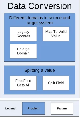
Therefore, we propose a pattern language of data conversion patterns. Avgeriou et al. (APRS03) define a pattern language as “a set of related patterns that collaborate inside the boundaries of an application domain”. The way the patterns are related within a language varies. Gamma et al. (GHJV95) use a pattern language to show which patterns can be used in combination with other patterns, while Roberts and Johnson (RJ96) use the relationship to show the order in which patterns should be applied. We will follow the approach of Keller (Kel97) who structures his language according to the problem structure and provides alternative patterns for every problem.
The language consists of a list of problems of data conversion. For each problem it gives a description of the problem and an example that illustrates the problem, one or more patterns that solve this problem and a comparison of the patterns. This comparison is done using a table that contains the patterns‟ scores on each of the eight quality attributes. Using this table, designers can quickly get an impression of the tradeoffs of each pattern and on which points one pattern scores better than the others. New problems and patterns that address that problem can simply be added in the future, and new patterns holding new solutions can be added to existing problems to give designers new ways of solving the problem.
32
been discovered in multiple systems. It is an important element of patterns that the solution is one that has been applied more than twice. This „Rule of Three‟ ensures that the pattern documents tried and true application, not just a good idea without real use behind it.”
In short, you cannot invent a pattern, you have to discover it. A pattern should describe a proven successful solution. The patterns that are given on the next pages all have their roots in practical experience of data conversion designers working at Quinity, the solutions described in the patterns have been used successfully in real systems. The experience documented in the patterns was obtained by interviews with designers. They shared experiences and knowledge about data conversion design. This experience was analyzed and searched for problems and solutions that reoccurred and were generic; they could be described and explained without referring to the particular case and context they occurred in and could be applied in other contexts. These problems and solutions were worked out and grew into design patterns which were again discussed with the designers to check whether they indeed described the experience they had. After that, the patterns were evaluated with a different group of experts, as is discussed in chapter 4.
The patterns were also tested by using them in simple test systems. The solutions of the patterns were implemented in Java code. We put some example data in a test database and ran the program on this data. The resulting data had to match the expected result for the test to be accepted. The important parts of the Java code are included in the patters and the test data is the same as the data in the example used to explain the solution in the pattern. These tests show the patterns indeed work as they should and the Java code can help a designer better understand the pattern it the way it can be implemented.
The database that was used for the test was PostgreSQL version 8.3 and the test system was implemented in Java SE 6 update 11. All tests worked as expected without problems.
33
Legend:
Data Conversion
Splitting a value
First Field
Gets All Split Field
Different domains in source and
target system
Legacy Records
Map To Valid Value
Enlarge Domain
[image:33.595.158.439.156.568.2]Problem Pattern
35
Problem 1: Different domains in source and target system
Example
A university has an information system that stores the courses its students have completed and what marks the students received for the exams they made. For every exam the database contains a record containing the student number, the course number and the mark the teacher has given. The mark is stored as a natural number and can have values of zero or above.
When the university develops a new system to replace the old information system, they design the storage of marks a little differently. The designers reason that marks can only have values between 1 and 10. Zero or anything above 10 should not be given. To make sure this cannot be done by accident the database restricts the allowed value of marks to 1 to 10.
For the conversion designers this is a problem. The source system could contain values of 0 and greater than 10, but these cannot be stored in the target system.
Abstraction
In this problem, a single field from the source system is converted to a single field in the target system. The domain of the field in the source system differs from the domain of the field in the target system. This means that in the source system, this field can have values that are not allowed as values in the corresponding field in the target system.
Field
Domain: a, b, c
Field
Domain: b, c, d
Source system
Target system
Remark about cardinality
36
Patterns that solve this problem are:
Legacy Records provides a method that can guarantee completeness. Enlarge Domain focuses on completeness with less effort.
Map to Valid Value focuses on effort and requires no changes in the target system.
The following table summarizes the scores of the patterns on the eight quality attributes: Com plet en ess T echni cal imp act Functi ona l imp act M ai nt ain ab ili ty Ef for t t o imp lement Un derstan dab ilit y Data in te gr it y T race ab ilit y
Legacy Records + - □ - - - + +
Enlarge Domain + □ - + □ + + +
37
Legacy Records
Intent
Convert fields from the source system that contain values that are not allowed in the target system (has a different domain) without losing information by marking records as being ‘legacy’.
Motivation
Consider the mark registration system of the example. Suppose the university is required by law to store all marks of students for a number of years after their graduation. So when the marks are converted to the new marks registration system, all marks have to be brought to the target system without modification.
However, the older marks are only stored for archiving purposes. It is unlikely they have to be accessed very often, and they do not have to be changed later on. So the old marks have to be stored, but they do not have to be stored in the same way as new marks, and do not need to be as accessible as new marks.
With Legacy Records all marks can be converted unchanged, without altering the domain (allowed values) for new marks.
Applicability
Use Legacy Records when completeness of the conversion is of importance and loosing data is not an option. Legacy Records can only be applied when changing the target system is possible.
Solution
In this solution, we do not change the values that the target field can hold. Instead, we introduce the concept of a legacy record. A record in the target system becomes a legacy record if a field in the source system is converted to a field in the record but contains a value that is not valid for that field in the target system.
In order to store this information, two new fields are added: ‘isLegacy’ and ‘legacyDetails’. The first stores whether the record is a legacy record, the second stores the invalid information that cannot be stored in the field that should contain that information. When the source field contains a value that is also valid in the target system, we simply set the target field to that value. Additionally, the ‘isLegacy’ field is set to ‘false’ and the ‘legacyDetails’ field is left empty.
38
Note that, because new fields are added to the target system, a ‘one to one’ mapping becomes a ‘one to many’ mapping when applying Legacy Records. Such a mapping may be best described using the ‘push’ fashion.
Example
In the example of the marks registration system, this solution means that we add columns ‘isLegacy’ and ‘legacyDetails’ to the table holding the marks. For all marks between 1 and 10, we copy the mark to the target field, set the value of ‘isLegacy’ to false and leave the field ‘legacyDetails’ empty. When we encounter a mark of 0 or above 10, we leave the mark in the target system empty, set ‘isLegacy’ to true and copy mark to the field ‘legacyDetails’.
Now all marks, including invalid ones, can be converted to the target system, without removing the restriction that new marks have to be between 1 and 10. Suppose the source system stored the marks in the following database table:
courseId studentId mark
c123 s074589 7
c123 s045944 4
c123 s044846 11
c123 s089657 0
The target system has uses the same columns, but we add ‘isLegacy’ and ‘legacyDetails’. The information from the table above would then be converted to the following table in the target system:
courseId studentId mark constraint: value >=1
and value <= 10 isLegacy legacyDetails
c123 s074589 7 false null
c123 s045944 4 false null
c123 s044846 null true 11
c123 s089657 null true 0
Implementation
The following steps are needed to implement the Legacy Records pattern in Java:
- Two classes (SourceRecord and TargetRecord) are defined for the source table and the target table. These classes hold instance variables that mirror the columns of the database tables.
39
- For every SourceRecord object the appropriate TartetRecord object is constructed. The TargetRecord isLegacy field is set to true if the SourceRecord holds values that are not allowed in the target system. In that case the legacyDetails field is filled with that value.
- Every TargetRecord object gets written to the target database.
The example could be implemented as follows: public void runConversion()
{
Vector<SourceRecord> sourceRecords = DataFile.getSourceRecords(); Vector<TargetRecord> targetRecords = new Vector<TargetRecord>();
for( int i = 0; i < sourceRecords.size(); i++ ) {
TargetRecord tr = transformation( sourceRecords.get( i ) ); targetRecords.add( tr );
}
DataFile.storeTargetRecords( targetRecords ); }
public TargetRecord transformation( SourceRecord sr ) {
int courseId = sr.getCourseId(); int studentId = sr.getStudentId(); int mark = sr.getMark();
boolean isLegacy = false; int legacyDetails = 0;
if( mark < 1 || mark > 10 ) {
isLegacy = true; legacyDetails = mark; mark = 0;
}
return new TargetRecord( courseId, studentId, mark, isLegacy, legacyDetails );
}
Quality attributes
Completeness: The upside of this solution is that we are able to convert all information from the source system, also the invalid information, without losing any data. Score: ‘+’.
Technical impact on target system: The target system needs to be changed significantly. First of all, the fields ‘isLegacy’ and ‘legacyDetails’ must be introduced in the database. The system must be altered so it can handle these new fields and stores information in the database correctly. Finally, there must be some way to view the legacy information which requires changes in the logic and user interface. Score: ‘-’.
40
information is not affected by the changes: it is still bound by the limitations the system was designed with.
A problem arises when the target field cannot be empty or when it is used in calculation by the system because when using Legacy Records, the field may remain empty when the record is marked ‘isLegacy’. Solving this problem may introduce changes to the functionality of the target system. Score: ‘□’.
Maintainability: The solution introduces extra fields in the database, which also introduces extra maintenance. In the future, the use of legacy fields may seem odd and unwanted. Score: ‘-’.
Effort to implement: This solution is a lot of work to implement. The system needs to be changed in various locations. Score: ‘-’.
Understandability: The solution is complicated and may be difficult to explain. Score: ‘-’.
Data integrity: There are no integrity issues with this solution. Score: ‘+’.
Traceability: All the original values from the source system are copied to the target system, either to the target field or the ‘legacyDetails’ field. Thus, all records and values can be traced back to their origin. Score: ‘+’.
Related patterns
41
Enlarge Domain
Intent
Convert fields from the source system that contain values that are not allowed in the target system (has a different domain) without losing information.
Motivation
Suppose the marks from the marks registration system in the example all need to be converted unchanged, i.e. the completeness of the conversion of these marks is very important. Because some of the marks may have values that are outside of the domain of the target system are of students that are not yet graduated, these marks need to be fully accessible; new marks and old marks cannot be treated differently. The restricted domain in the target system, limiting allowed marks to 1 to 10, is not crucial to the operation of the target system. So, the completeness of the data conversion takes priority over the functionality of the target system.
Applicability
Use Enlarge Domain when completeness of the conversion is of importance and loosing data is not an option. Enlarge Domain can only be applied when changing the target system is possible and functional changes to the target system are allowed.
Solution
The problem is that the field that needs to be converted can have values in the source system that are invalid in the target system. This can be solved by making these values valid in the target system. This means that the domain (set of valid values) in the source system must be a subset of the domain (set of valid values) in the target system.
This means that any constrains in the database limiting the allowed values in that field have to be removed, but also that in the systems’ logic such constrains must be altered. The user interface must be able to show values other than 1 to 10 and the user must be able to enter values other than 1 to 10.
Example
42
courseId studentId mark
c123 s074589 7
c123 s045944 4
c123 s044846 11
c123 s089657 0
The target system uses a similar table, except that a database constraint limits the ‘mark’ column to values greater or equal to 1 and smaller or equal to 10. Applying the solution means removing this constraint. The target system now accepts any numeric value for the marks. Now, every mark can be converted to the target system because any value in the source system is also valid in the target system. The resulting table in the target system looks the same as the original table in the source system.
Implementation
This pattern does not contain an implementation as there is no need to actually transform the data. After removing the constraint limiting the allowed values from the target system, the data can be moved from source to target unmodified.
Quality attributes
Completeness: With this solution, all data can be moved to the target system. The solution is therefore complete. Score: ‘+’.
Technical impact in target system: For this solution to be implemented, the target system needs to be changed. The change is not very big as only the list of allowed values needs to be enlarged. Score: ‘□’.
Functional impact on target system: This solution means that the target system becomes functionally different from how it was designed in the first place. The restriction on valid values was put into place for a reason; in the example the designers wanted to only allow marks between 1 and 10 so teacher could not register invalid marks by accident. This safety measure would have to be removed to enable the conversion with this solution. Score: ‘-’.
Maintainability: The solution has no maintainability issues. Score: ‘+’.
Effort to implement: This solution is moderately difficult to implement. It is important to check whether changing the number of allowed values has any impact on the rest of the system. Other parts may be expecting only the original range.