Transactions of the 17th International Conference on Structural Mechanics in Reactor Technology (SMiRT 17)
Prague, Czech Republic, August 17 –22, 2003
Paper # K04-5
Study on the Soil-Structure Interaction Model under Vertical Earthquake
Motions
Noriyoshi Ogawa1), Atsushi Tachibana1), Yasuaki Fukushima2), Yoshinori Mihara2)
1) Chubu Electric Power Co., Inc., Nagoya, Japan 2) Kajima Corporation, Tokyo, Japan
A
BSTRACTMulti-degree-of-freedom (MDOF) parallel model has already been proposed and introduced to aseismic design for some nuclear power plant (NPP) buildings in Japan as one of the various soil-structure interaction models under horizontal earthquake motions. However, there are no previous references or research works on MDOF parallel model under vertical earthquake motions. Therefore, to establish the analytical method using proposed MDOF parallel vertical model, the following topics are theoretically and practically studied in this paper.
1) Theoretical application of MDOF parallel vertical model
2) Seismic simulation analysis with actual observation record under vertical motions 3) Proposal of MDOF parallel vertical model for aseismic design under vertical ones
KEY WORDS: nuclear power plant building, reactor building, seismic response analysis, vertical earthquake motion, soil-structure interaction, evaluation of foundation input motion, dynamic soil stiffness, horizontally layered soil, MDOF parallel model, observation record, simulation analysis, simple model for aseismic design
1. INTRODUCTION
MDOF parallel model illustrated in Fig.1 has already been proposed and introduced to aseismic design for some nuclear power plant buildings in Japan as one of the various soil-structure interaction models under horizontal earthquake motions [1]. It will also be necessary to consider dynamic vertical earthquake motions for near future aseismic design in Japan, although the current one is based on static vertical seismic force. However, there are no previous references or research works on MDOF parallel model under vertical earthquake motions. Considering such a
background, MDOF parallel vertical model shown in Fig.2 is theoretically and practically studied in this paper.
First, to evaluate MDOF parallel vertical model theoretically, it is
compared to one- and three-dimensional wave propagation theory from the viewpoint of the evaluation on foundation input motion through soils, dynamic soil stiffness due to building vibration and application to horizontally layered soils. Next, using actual vertical earthquake observation record in a nuclear power plant site, seismic simulation analysis is carried out with proposed MDOF parallel vertical model for the BWR reactor building and surrounding soils. As the result of that, it is shown that MDOF parallel vertical model simulates the dynamic response characteristics of observation records better than the conventional model.
Finally, based on the seismic simulation technique of MDOF parallel vertical model, more design-oriented model is proposed with emphasis on the maximum dynamic response of buildings.
2. THEORETICAL EVALUATION ON MDOF PARALLEL VERTICAL MODEL
The evaluation on foundation input motion and dynamic soil stiffness is very important to construct a soil-structure interaction model under vertical earthquake motions. From this viewpoint, proposed MDOF parallel vertical model is compared to one-and three-dimensional wave propagation theory for an assumed homogeneous soil. Through the
Fig.1 MDOF parallel model (Horizontal)
Fig.2 MDOF parallel model (Vertical)
comparison, influence over distance between vertical soil nodes, area of the model, boundary conditions and also application to horizontally layered soils are studied to evaluate the proper model.
2.1 Evaluation on Foundation Input Motion
Adequate distance h between each vertical node of soil columns is evaluated to obtain the response similar to one-dimensional wave propagation theory. Properties of an assumed homogeneous soil are S-wave velocity Vs=700m/s,
P-wave velocity Vp=2000m/s and soil density 20.6kN/m3. Also, amplitudes of transfer function from 500m-depth level to
ground surface are compared between MDOF parallel vertical model and one-dimensional wave propagation theory.
Here, vertical distance h of each node is calculated by Eq. (1) and the values of parameter α are 2, 5, 10 and 20 for
parametric study.
h = Vp / (α ×fmax) (1)
α : Constant regarding the wavelength of P wave
fmax : Maximum frequency to be considered (=20Hz)
The soil column model for α=5 is shown in Fig.3 and comparison of the results are shown in Fig.4. Therefore, for
500m-depth model, the result by α=5 agrees well with the result by one-dimensional wave propagation theory up to
10Hz which is almost upper limit of dominant frequency of vertical response of NPP buildings. Also, the result by
α=20 agree better with it up to 20Hz.
2.2 Evaluation on Dynamic Soil Stiffness
Besides foundation input motion, the evaluation on dynamic soil stiffness, i.e. impedance is also important to construct a proper soil-structure interaction model. Thus, impedances by Tajimi vibration admittance theory [2]
based on three-dimensional wave propagation theory and by MDOF parallel vertical model are compared, exciting the corresponding building foundation of the model. Homogeneous soil properties same as before are assumed. MDOF parallel vertical model shown in Fig.5 is used in this comparison, which is the detailed
axisymmetric model for α=20 with
four soil columns in the area of 4 times equivalent foundation radius. The shear stiffness between soil columns is evaluated from the surface area at midpoint and S-wave velocity Vs. Impedances by the theory and MDOF parallel vertical model are compared in Fig.6. Both real and imaginary parts of
impedance by MDOF parallel vertical model mostly match those by Tajimi vibration admittance theory.
Based on the detailed MDOF parallel vertical model well simulating the theoretical result, parametric studies in the following are carried out regarding model depth and boundary condition for side and bottom of the model.
For the influence on model depth, impedances by 100m-depth, 300m-depth and 500m-depth MDOF parallel vertical
model are computed, which is based on the simple model for α=5 with two soil columns in the area of 1.5 times
equivalent foundation radius. Comparison between these and also the 500m-depth detailed model results is shown in Fig.7. All the results by simple models above generally show enough agreement with the result by detailed model. But, going into detail, the result by 100m-depth simple model is different from that by detailed model. Therefore, at least 300m depths should be needed in MDOF parallel vertical model.
For the influence on side boundary, impedances by three MDOF parallel vertical models with and without viscous
side boundary are computed. Basic one has a viscous side boundary for α=5 with two 300m-depth soil columns in the
area of 1.5 times equivalent foundation radius. Second one has a free side boundary for α=5 with two 300m-depth soil
# of Nodes
26
500 m
~
~
~
~
h=20m
0 5 10 15
0 2 4 6 8 10
1D Wave Propagation Theory
Proposed Method (α=2)
Proposed Method (α=5)
Proposed Method (α=10)
Proposed Method (α=20)
Amp
. of
A
cc.
T
rans
.
F
u
nc
.
(G
L0
.0
M(
2E
)/
GL
-5
0
0
M(
EF
))
Frequency (Hz)
0 0.5 1 1.5
10 12 14 16 18 20
1D Wave Propagation Theory
Proposed Method (α=2)
Proposed Method (α=5)
Proposed Method (α=10)
Proposed Method (α=20)
A
m
p
. of
A
cc.
T
ran
s.
F
u
nc
.
(G
L0
.0
M(
2
E
)/
G
L
-5
0
0
M
(E
F
))
Frequency (Hz) Fig.3 Example of soil column model
(a) 0 to 10Hz
(b) 10 to 20Hz
columns in the area of 1.5 times equivalent foundation radius. Third one
has a free side boundary for α=5 with four 300m-depth soil columns in
the area of 4.0 times equivalent foundation radius. Comparison between these and also the detailed model results is shown in Fig.8. Therefore, when free side boundary is applied, MDOF parallel vertical model had better consider the larger area such as 4.0 times equivalent foundation radius.
For the influence on bottom boundary, impedances by three MDOF parallel vertical models with and without viscous side/bottom boundary are computed. Basic one has a free side and viscous bottom boundary for
α=5 with four 300m-depth soil columns in the area of 4.0 times
equivalent foundation radius. Second one has a free side and fixed
bottom boundary for α=5 with four 300m-depth soil columns in the area
of 4.0 times equivalent foundation radius. Third one has a free side and
fixed bottom boundary for α=5 with four 500m-depth soil columns in
the area of 4.0 times equivalent foundation radius. Comparison between these and also the detailed model results is shown in Fig.9. When fixed bottom boundary is applied, apparent differences between them are observed due to the reflect wave at bottom. Therefore, although slightly improved by deeper model, viscous bottom boundary is recommended for MDOF parallel vertical model.
Finally, from the viewpoint of evaluation on dynamic soil stiffness, it is recommended that simple MDOF parallel vertical model has a free
side and viscous bottom boundary for α=5 with four 300m-depth soil
columns in the area of 4.0 times equivalent foundation radius.
-1 1012 0 1 1012 2 1012 3 1012 4 1012 5 1012
0 5 10 15 20
Admittance Theory(Real) Admittance Theory(Imag.) Proposed Method(detailed[α=20],Real) Proposed Method(detailed[α=20],Imag.)
Dy
nam
ic
C
o
m
p
le
x
S
o
il
S
p
rin
g
(N/m)
Frequency (Hz)
-1 1012 0 1 1012
2 1012 3 1012 4 1012 5 1012
0 5 10 15 20
Simple[α=5],Depth=100m (Real) Simple[α=5],Depth=100m (Imag.) Simple[α=5],Depth=300m (Real) Simple[α=5],Depth=300m (Imag.) Simple[α=5],Depth=500m (Real) Simple[α=5],Depth=500m (Imag.) Detailed[α=20],Depth=500m (Real) Detailed[α=20],Depth=500m (Imag.)
D
ynam
ic
C
o
m
p
le
x
S
o
il Sp
ri
n
g
(
N
/m)
Frequency (Hz)
-2 1012 0 2 1012 4 1012 6 1012
0 5 10 15 20
Simple[α=5], Bottom:depth 300m. w/ viscous BC(Real) Simple[α=5], Bottom:depth 300m. w/ viscous BC(Imag.) Simple[α=5], Bottom:depth 300m. w/ fix BC(Real) Simple[α=5], Bottom:depth 300m. w/ fix BC(Imag.) Simple[α=5], Bottom:depth 500m. w/ fix BC(Real) Simple[α=5], Bottom:depth 500m. w/ fix BC(Imag.) Detailed[α=20], Bottom:depth 500m. w/ viscous BC(Real) Detailed[α=20], Bottom:depth 500m. w/ viscous BC(Imag.)
D
y
n
am
ic
C
o
m
p
le
x
So
il
S
p
ri
n
g
(N
/m
)
Frequency (Hz)
Fig.5 MDOF parallel vertical model
500
(Side:Viscous Boundary) (Bottom:Viscous Boundary)
48.5 24.25 48.5 72.25
194
h=5m
(α=20)
60.625 36.375 60.625
(1.0d)
(0.5d)
(1.0d)
(1.5d)
(4.0d)
~ ~ ~
~ ~~ ~~
~ ~ ~
~ ~~ ~~
Unit: m
Fig.6 Comparison of impedance Fig.7 Influence on model depth
Fig.8 Influence on side B.C. Fig.9 Influence on bottom B.C.
-1 1012 0 1 1012 2 1012 3 1012 4 1012 5 1012
0 5 10 15 20
Simple[α=5], Side:1.5d w/ viscous BC(Real) Simple[α=5], Side:1.5d w/ viscous BC(Imag.) Simple[α=5], Side:1.5d w/ free BC(Real) Simple[α=5], Side:1.5d w/ free BC(Imag.) Simple[α=5], Side:4.0d w/ free BC(Real) Simple[α=5], Side:4.0d w/ free BC(Imag.) Detailed[α=20], Side:4.0d w/ viscous BC(Real) Detailed[α=20], Side:4.0d w/ viscous BC(Imag.)
Dyn
am
ic
C
o
m
p
lex So
il S
p
ri
n
g
(
N
/m)
Frequency (Hz)
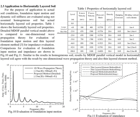
2.3 Application to Horizontally Layered Soil For the purpose of application to actual soil conditions, foundation input motion and dynamic soil stiffness are evaluated using not assumed homogeneous soil but actual horizontally layered soil properties. Table 1 shows the horizontally layered soil properties. Detailed MDOF parallel vertical model above is compared to one-dimensional wave propagation theory for evaluation of foundation input motion and thin layered element method [3] for impedance evaluation. Comparisons for evaluation of foundation input motion and impedance are shown in
Fig.10 and Fig.11. Similar to the results in homogeneous soil, results by MDOF parallel vertical model in horizontally layered soil agree with the result by one-dimensional wave propagation theory and also thin layered element method.
2.4 General Concept of MDOF Parallel Vertical Model
It is clear from the results of section 2.1 to 2.3 that proposed MDOF parallel vertical model could be used as one of the soil-structure interaction models under vertical earthquake motions. Also, Fig.12 shows the general concept and evaluation procedures of proposed MDOF parallel vertical model: evaluation on distance between vertical soil nodes, mass of soil nodes, axial and shear stiffness of soils and boundary conditions etc.
3. SEISMIC SIMULATION ANALYSIS UNDER VERTICAL MOTIONS
To investigate practical validity of MDOF parallel vertical model, seismic simulation analysis is carried out with the model for the BWR reactor building and surrounding soils, using an actual vertical earthquake observation record in a nuclear power plant site. Vertical observation record of Enshunada (Omaezaki) earthquake, which occurred in October 11th, 1997, is used for this simulation analysis. The earthquake is reported as JMA magnitude Mj4.9, focal distance from the observation site 43km and epicentral distance from the observation site 23km.
3.1 Analytical Conditions
Soil-structure interaction model consists of soil part and BWR reactor building part is used in this simulation analysis. The soil part is detailed MDOF parallel vertical model described in Chapter 2 shown in Fig.13 and the building part is multi-degree-of-freedom model shown in Fig.14. Vertical seismic response model of the building properly consider the axial stiffness of RC structural members and bending/shear stiffness of steel roof trusses. Elastic modulus of RC is derived from the test results of concrete pieces. Damping constants of RC and steel are assumed to be 5% and 2% respectively. The detailed evaluation of the building refers to [4]. Soil properties in Table 1 are used. For reference purpose, conventional vertical soil spring model with embedment [4] is also evaluated. The model is explained such that soil under foundation is evaluated as a vertical spring based on three-dimensional wave propagation theory and embedded soil surrounding building is also evaluated as vertical side spring based on Novak’s method [5]. Then, the stiffness of dynamic soil spring is assumed to be constant independent of frequency and the damping of it is assumed to be proportional to frequency.
Level S-wave
Velocity P-wave
Velocity Density
(m) (m/s) (m/s) (kN/m3)
0.0 - - -
--4.0 180 400 0.3730 17.7 0.05 1m×4
▽ -23.0 670 1500 0.3754 20.6 0.05 3m×1,4m×4
-25.0 670 1500 0.3754 20.6 0.05 2m×1
-35.0 750 1780 0.3921 20.6 0.05 5m×2
-46.0 850 1780 0.3523 20.6 0.05 3m×2,5m×1
-92.0 850 1920 0.3781 20.6 0.05 3m×2,5m×8
-500.0 850 2100 0.4020 20.6 0.05 4m×2,5m×80
Lower Level of Base Mat
Dividing vertical soil columns Damping
Constant Poisson's
Ratio
0 5 10 15
0 5 10 15 20
1D Wave Propagation Theory [-23m(2E)/-500m(E+F)] Proposed Method (Detailed) [-23m(2E)/-500m(E+F)]
A
m
p
. of
A
cc.
T
rans
. F
u
nc
.
(G
L
-2
3
M/
G
L
-5
0
0
M)
Frequency (Hz) -1 1012 0
1 1012
2 1012
3 1012
4 1012
0 5 10 15 20
Thin Layered Element Method(Real) Thin Layered Element Method(Imag.) Proposed Method(detailed,Real) Proposed Method(detailed,Imag.)
Dy
n
amic
C
o
m
p
le
x
S
o
il
S
p
rin
g
(N/m
)
Frequency (Hz)
Table 1 Properties of horizontally layered soil
Fig.10 Evaluation of foundation input motion
Input motion to MDOF parallel vertical model is estimated from 2E wave (E: incident wave) at GL-500m obtained by one-dimensional wave propagation theory with observation record at GL-25m in free field. Fig.15 illustrates the evaluation flow for input motion to MDOF parallel vertical model.
477m
48.5 24.25 48.5 72.75
194
60.625
157.625
36.375 60.625
(1.0d) (0.5d) (1.0d) (1.5d)
97.0
(4.0d)
23m Side : Viscous
Boundary
Bottom : Viscous Boundary Free filed
(Soil Columns)
~
~ ~~ ~~ ~~
~ ~
Fig.12 General concept and evaluation procedures of proposed MDOF parallel vertical model
Fig.13 Soil part of MDOF parallel vertical model
Fig.14 Building part of MDOF parallel vertical model
Fig.15 Evaluation flow for input motion to the model Shear stiffness of soil (Ks)
Vertical distance of soil nodes(h)
max
×
p V h
f
α =
l
mid s s
A G
K =
Notes) This definition is derived from a 1st order axisymmetric isoparametric element.
mid
A
Weight of soil (w) Axial stiffness of soil Axial stiffness of soil ((KKNN))
h A E
K s
N=
: Maximum freq. (=20Hz) : Constant regarding wave length : P-wave velocity
max
p V
f
α
( = 5 to 20)
hA
w=γ
Base mat
Near area
r
h About 3 times r
~ ~ ~ ~ ~~
~ ~ ~ ~ ~ ~ ~ ~
Bottom : Viscous boundary
~ ~ ~ ~ ~
S
id
e bo
u
n
dar
y
:
F
ree
~ ~ ~ ~
About 6 to 10 times r Intermediate
area Far area
h W
d 0
l
h W
d 0
l
h
d 0
l
h
d 0
l
d 0
h
2
l
2
l
d 0
h
2
l
2
l
: Area
: Distance of soil nodes : Density of soil
A h
γ
(=πl l( +2 ))d : Area
: Distance of soil nodes : Density of soil
A h
γ
(=πl l( +2 ))d
: Young’s modulus of soil
A h Es
: Distance of soil nodes
: Area(=πl l( +2 ))d : Young’s modulus of soil
A h Es
: Distance of soil nodes
: Area(=πl l( +2 ))d
: Distance between soil columns : Shear modulus of soil
A G
mid s
: Area(=πh(l+2 ))d
l : Distance between soil columns : Shear modulus of soil
A G
mid s
: Area(=πh(l+2 ))d
l
F E
2E Proposed model (MDOF parallel)
-500m
Bottom : Viscous bounadry Side : Viscous
boundary
Observation
1D wave propagation
theory
Bld. model
-25.0m
Comparison Simulation Observation
3.2 Analytical Results
(1) Acceleration Time History
Fig.16 shows the acceleration time history of observation record at GL-25m in free field and also comparison between acceleration time histories of observation records and analytical results by MDOF parallel vertical model at 3rd floor inner box wall, end and center of roof truss. Results by MDOF parallel vertical model show mostly good agreements with the observation records.
(2) Acceleration Response Spectra
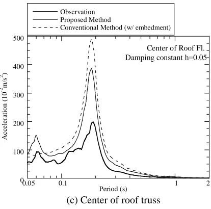
Fig.17 shows the comparison between acceleration response spectra (damping constant h=5%) of observation records and analytical results by MDOF parallel vertical model and conventional vertical soil spring model at 3rd floor inner box wall, end and center of roof truss.
For the 1st mode appearing around 0.2 second, results by not only MDOF parallel vertical model but also conventional vertical soil spring model show mostly good agreements with the observation records. But response values by conventional vertical soil spring model are greater than those by MDOF parallel vertical model.
For the 2nd mode appearing around 0.06 second, results by MDOF parallel vertical model show good agreements with the observation records. On the other hand, results of conventional vertical soil spring model can’t show even the peak configuration of 2nd mode itself. Since the mode excited by the surrounding soils upper foundation is almost corresponding to such a 2nd mode, it is concluded that MDOF parallel vertical model can properly evaluate the influence on the surrounding soils upper foundation. -10 -5 0 5 10
0 2 4 6 8 10 12
Free field : GL-25m Observation A cc eler ati o n ( 1 0 -2m/ s 2) Time(s) -10 -5 0 5 10
0 2 4 6 8 10 12
3rd Fl. Inner Box Wall Observation A cc eler ati o n ( 1 0 -2m/ s 2) Time(s) -10 -5 0 5 10
0 2 4 6 8 10 12
3rd Fl. Inner Box Wall Calculation(Proposed) A cc eler ati o n ( 1 0 -2m/ s 2) Time(s) -15 -10 -5 0 5 10 15
0 2 4 6 8 10 12
End of Roof Fl. Observation A cc eler ati o n ( 1 0 -2m/ s 2) Time(s) -15 -10 -5 0 5 10 15
0 2 4 6 8 10 12
End of Roof Fl. Calculation(Proposed) A cc eler ati o n ( 1 0 -2m/ s 2) Time(s) -100 -50 0 50 100
0 2 4 6 8 10 12
Center of Roof Fl. Observation A cc eler ati o n ( 1 0 -2m/ s 2) Time(s) -100 -50 0 50 100
0 2 4 6 8 10 12
Center of Roof Fl. Calculation(Proposed) A cc eler ati o n ( 1 0 -2m/ s 2) Time(s) 0 10 20 30 40 50 0.1 1 Observation Proposed Method
Conventional Method (w/ embedment)
Acc eler at io n ( 1 0 -2m/s 2) Period (s)
3rd Fl. Inner Box Wall Damping constant h=0.05
0.05 2 0 10 20 30 40 50 0.1 1 Observation Proposed Method
Conventional Method (w/ embedment)
Ac ce le ra ti o n ( 1 0 -2 m/ s 2 ) Period (s) 0.05 2
End of Roof Fl. Damping constant h=0.05
Fig.16 Comparison of acceleration (a) Input motion (GL-25m)
(b) Observation (3F I.W.)
(c) Analysis (3F I.W.)
(d) Observation (End of roof)
(e) Analysis (End of roof)
(f) Observation (Center of roof)
(g) Analysis (Center of roof)
Fig.17 Comparison of response spectra (a) 3F Inner Box Wall
4. PROPOSAL OF MDOF PARALLEL VERTICAL MODEL FOR ASEISMIC DESIGN
Based on the detailed MDOF parallel vertical model verified by seismic simulation analysis, using basic design earthquake motion and response analysis model for design, more design-oriented model is proposed with emphasis on the dynamic vertical responses of buildings up to 10Hz which is almost upper limit of dominant frequency of them.
4.1 Evaluation Conditions
Fig.18 shows a vertical response analysis model of a BWR reactor building for design and Fig.19 shows basic design vertical earthquake motion. Using the design model and earthquake motion, the vertical responses by more design-oriented model which is suggested in Chapter 2 are compared to those by the detailed MDOF parallel vertical model verified by seismic simulation analysis. All analytical cases are shown in Table 2. For reference purpose, conventional vertical soil spring model without embedment is also evaluated.
4.2 Evaluation Results
Generally speaking, response evaluation of roof truss is most important for reactor buildings under vertical earthquake motions. Thus, to propose a simple MDOF parallel vertical model for design, response values are evaluated of interest in maximum response shear force and bending moment of roof truss. Comparisons of maximum response shear force and bending moment are shown in Fig.20 and Fig.21. First, response values by conventional vertical soil spring model are apparently greater than those by all MDOF parallel vertical models. Second, for the comparison
0 100 200 300 400 500
0.1 1
Observation Proposed Method
Conventional Method (w/ embedment)
Ac
ce
le
ra
ti
o
n
(
1
0
-2m/
s
2)
Period (s)
0.05 2
Center of Roof Fl. Damping constant h=0.05
-600 -400 -200 0 200 400 600
0 20 40 60 80
Ac
ce
le
ra
ti
on
(
1
0
-2 m/
s
2 )
Time(s)
MAX:300cm/s2
Fig.17 Comparison of response spectra (c) Center of roof truss
Fig.18 Building model for design
Fig.19 Basic design vertical earthquake motion
Table 2 Analytical cases for design model
Case # # of soil
columns Depth α
*) Embment Side BC Bottom BC
#1 4 500m 20 W/ Viscous Viscous
#2 4 300m 5 W/ Viscous Viscous
#3 4 300m 5 W/ Free Viscous
#4 4 300m 5 W/ Free Fix
Conventional - - - W/O - -
between MDOF parallel vertical models, listed in order of increasing response values are the detailed one (#1), the
simple one which has a free side and viscous bottom boundary for α=5 with four 300m-depth soil columns in the area
of 4.0 times equivalent foundation radius (#3) and the simple one which has a free side and fixed bottom boundary for
α=5 with four 300m-depth soil columns in the area of 4.0 times equivalent foundation radius (#4). The difference
between viscous condition with free field (#2) and free (#3) on side boundary doesn’t apparently shown.
Following the results above and also in section 2.2, more design-oriented model such as #3 is adequately proposed with emphasis on the dynamic vertical responses of buildings up to 10Hz which is almost upper limit of dominant frequency of them.
5. CONCLUSION
In this study, MDOF parallel vertical model illustrated in Fig. 2 is proposed similar to horizontal one. As the results of various evaluations, MDOF parallel vertical model can simulate more accurate vertical responses than conventional one from the viewpoints of not only wave propagation theory but also actual seismic simulation analysis.
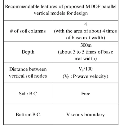
Based on the detailed MDOF parallel vertical model verified by seismic simulation analysis, more design-oriented model shown in Table 3 is adequately proposed with emphasis on the dynamic vertical responses of buildings up to 10Hz which is almost upper limit of dominant frequency of them.
REFERENCES
[1] NUREG/CR-6241: Technical Guidelines for Aseismic Design of Nuclear Power Plants, June 1994
[2] Tajimi, H. et al.: Research on Dynamic Spring of Foundation Bottom-ground According to Elastic Theory (Part1, Part2), Summaries of Technical Papers of Annual Meeting, Architectural Institute of Japan, October 1975, pp.395-398
[3] Tajimi, H. and Shimomura, Y.: Dynamic Analysis of Soil-structure Interaction by the Thin Layered Element Method, J. Struct. Constr. Eng., Architectural Institute of Japan, No.243, May 1976, pp.41-51
[4] Kuno, M., Motohashi, S., Mizuno, J. et al.: Simulation Analyses of Measured Seismic Vertical Response of a Nuclear Reactor Building (Part1, Part2 and Part3), Summaries of Technical Papers of Annual Meeting, Architectural Institute of Japan, September 1994, pp.1691-1696
[5] Novak, M. et al.: Dynamic Soil Reactions for Plane Strain Case, Proc. of ASCE, EM4, 1978, pp.953-959 # of soil columns
4
(with the area of about 4 times of base mat width)
Depth
300m
(about 3 to 5 times of base mat width)
Distance between vertical soil nodes
Vp/100 (Vp : P-wave velocity)
Side B.C. Free
Bottom B.C. Viscous boundary Recommendable features of proposed MDOF parallel
vertical models for design
Fig.20 Comparison of maximum shear force Fig.21 Comparison of maximum bending moment
Table 3 Features of proposed model for design 0
3000 6000 9000 12000
0 5 10 15 20
Proposed(#1,500m,α=20, Side: viscous, Bottom:viscous)
Proposed(#2,300m,α=5, Side: viscous, Bottom:viscous)
Proposed(#3,300m,α=5,Side: free, Bottom:viscous)
Proposed(#4,300m,α=5,Side: free, Bottom:fix)
Conventinal(w/o embedment)
M
ax
im
u
m s
h
ea
r
fo
rc
e(
k
N
)
Distance from end of roof truss(m)
0 20000 40000 60000 80000
0 5 10 15 20
Proposed(#1,500m,α=20, Side: viscous, Bottom:viscous)
Proposed(#2,300m,α=5, Side: viscous, Bottom:viscous)
Proposed(#3,300m,α=5, Side: free, Bottom:viscous)
Proposed(#4,300m,α=5, Side: free, Bottom:fix)
Conventinal(w/o embedment)
A
b
s.
of m
ax
imu
m
b
e
nd
in
g
m
o
me
nt
(
k
N
m
)