1641 | P a g e
Reactive Fuzzy Logic Controller Simulation for Robot
Motion Planning
B. M. Bhairat
#1, M. R. Gosavi
2, V. M. Thakare
31
Department of Mathematics, Br. Balasaheb Khardekar College, Vengurla Dist- Sindhudurg (M.S.)
2Department of Mathematics, Maharashtra Mahavidyalaya, Nilanga Dist- Latur (M. S.)
3Department of Computer Science and Technology, Sant Gadage Baba Amravati University,
Amravati. (M. S.)
ABSTRACT
This work discusses the application of fuzzy logic based algorithms to robot motion control and compares their approaches. This application includes robotic vehicle navigation in a 2D environment. The authors create an approach which attempts to overcome this tendency of fuzzy algorithms with a “layered, goal-oriented” navigation strategy. Two layers are proposed: long-range versus short-range information assessment. The first layer uses long-range sensor data and the global goal angle to determine a direction that is both traversable (free of obstacles) and desirable (toward the goal). The second layer takes the way-point formed by the first layer as a sub goal. This layer produces a local trajectory which guides the robot toward the way-point while avoiding collisions with obstacles. A ring of short-range sensors is used to implement a reactive navigation algorithm wherein local direction and speed commands are generated in response to near obstacles as the robot seeks the way-point. Further, it is seen that the layered approach produces a smoother trajectory and avoids obstacles before coming in close proximity to them.
Keywords
:
Fuzzy Algorithms, Layered Approach, Local Trajectory, Navigation, Traversable And
Desirable
I. INTRODUCTION
The goal of autonomous robot operation is a topic of considerable research. Robots may frequently find
themselves in environments for which a reliable map of obstacles and terrain is unavailable due to the dynamics
of the environment, imprecise sensory data or simply a lack of prior knowledge of the environment [1]. In such
situations, it may be necessary for a robot to recalculate its trajectory online. While an end-to-end motion plan
for the robot in terms of gross motions over longer distances may remain valid, a response to a moving or
unforeseen obstacle may force the robot to alter its path in the middle of local obstacles while en route from the
initial configuration to the final goal.
Fuzzy algorithms execute in three major stages: fuzzification, inference, and defuzzification. In the fuzzification
1642 | P a g e
according to their levels of membership in fuzzy sets. These sets are given names which express qualities of the
input variable using easily understood linguistic terms. A membership function maps the value of the input
variable to a degree of membership in each of the fuzzy sets. The fuzzified value then, represents the level of
truth of each of these linguistic terms for a given input. For example, the angular direction of a near obstacle to a
mobile robot might have a universe of discourse of -90° to 90° where 0° denotes the current heading of the
robot.
II. PREVIOUS WORK DONE
D. Shi et al. [1] presents Robot Navigation in Cluttered 3D environments using preference-based fuzzy
behaviors. K. Tanaka [2] describes an introduction to fuzzy logic for practical applications. X. Yang et al. [3]
present a layered goal-oriented planning strategy for mobile robot navigation. P.G. Zavlangas et al. [4] present
industrial robot navigation and obstacle avoidance employing fuzzy logic. Also author took the support of Lab
VIEW PID Controller Toolkit User Manual [5], National Instruments Corporation, Austin.P. F. Muir et al. [6]
presents kinematic modeling of wheeled mobile robots. E. L. Hall et al. [7] describes motion planning using
fuzzy logic controller in Robotics: A User-Friendly Introduction. Z. L. Cao et al. [8] presents dynamic
omni-directional vision for mobile robots. Z .L. Cao, Y. Y. Huang, and E. L. Hall [9] presents region filling operations
with random obstacle avoidance for mobile robots. S. J. Oh et al. [10] presents calibration of an omni-directional
vision navigation system using an industrial robot. Kazuo Tanaka [11] presents design of model-based fuzzy
controller using Lyapunov‟s stability approach and its application to trajectory. C. V. Altrock et al. [12] presents
advanced fuzzy logic control technologies in automotive applications. B. M. Bhairat et al. [13] describes
implementation of crisp logic for robot control. B. M. Bhairat et al. [14] presents mathematical model for
trajectory control using fuzzy logic. B. M. Bhairat et al. [15] presents steering mobile robot using fuzzy logic
approach.
LIMITATIONS OF PREVIOUS WORK DONE
Fuzzy sets are capable of handling imprecise inputs, in the field of robotics. An input angle be sensed
inaccurately, its levels of truth according to the linguistic terms may vary while its relative membership levels in
the sets remain qualitatively the same. Generally the fuzzy algorithms can be used to implement efficient control
in a variety of settings with little conceptual difference in approach. The limitations of fuzzy algorithms exposed
by these articles are, perhaps the more interesting results of the comparison.
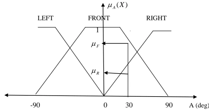
III. FUZZY SET DEFINITION WITH FUZZIFIED INPUTS
Sets are often defined to have the piecewise-linear shape shown so as to reduce the computational complexity of
determining set membership [6]. Typical shapes include triangular, square, singleton, Gaussian or asymmetric
types. Other variables commonly of interest in robotic applications include distance to an obstacle and speed of
1643 | P a g e
Figure 1 above shows a possible definition of fuzzy sets for how a “crisp” (real world) input angle θ might linguistically reflect the level to which the obstacle is left, in front, or right of the vehicle. Here, an angle of 30°
represents a direction having fuzzified degrees membership in the set of angles to the right (“rightness”) of
Rand frontness of
F. The inference stage applies the fuzzified input value to a rule base to determine acommand output. The rule base contains the operational intelligence of the system.
A(
X
)
LEFT
FRONT
RIGHT
1
F
R-90 0 30 90
A (deg)
Figure 1. Fuzzy set definition with a fuzzified input
An example rule apply to a mobile robot is given below.
If Obstacle Angle is RIGHT and Distance is NEAR Then
Steering Direction is LEFT_BIG ……… (1)
A rule base must cover all permutations of input variables having degrees of truth in all possible linguistic
terms. Hence the total number of rules N which must be represented in a rule base either by explicit statement or default action is given by in the relation:
mi i
p
N
………. (2)where m is the number of input variables (angle, speed, distance, etc.), and pi is the number of linguistic terms for the ithvariable [7]. Multiple rules in the rule base may have their predicate conditions satisfied to greater or lesser degrees by fuzzified input variables. Such rules are said to have fired. Each fired rule, then, possesses an
1644 | P a g e
product, etc.) stated by the rule (2). The defuzzification stage extracts a crisp command output from inferences
drawn from fired rules.
IV. MOBILE ROBOT NAVIGATION IN A 2D ENVIRONMENT
In applications of fuzzy logic to 2D robot motion planning, work in this area is focused on short range reactive
control. That is, robots were navigated by simply reacting to near obstacles upon detection while taking into
account a global goal direction. While such algorithms have frequently proven effective, they often encounter
situations in which the goal configuration becomes unreachable by the robot despite the availability of a
traversable path. More commonly, reactive fuzzy navigation may suffer from “shortsighted” behavior wherein
the angle to the final goal influences all steering decisions in unison with local sensor data. Situations then arise
in which short range sensors may not detect obstacles between the current configuration of the robot and the
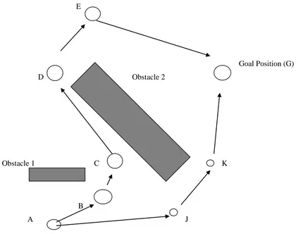
goal. In these cases, a path may be selected that is less desirable than others available. Figure 2 compares the
results of shortsighted behavior to an end-to-end path plan. Through purely reactive short-range fuzzy control,
the robot attempts to move in the direction of the goal at point B when obstacle 2 is still out of its perceptive
range. The undesirable path ABCDEG is the result. Clearly, with the benefit of long-range planning, path AJKG
would be seen as more desirable.
E
Goal Position (G)
D
Obstacle 2
Obstacle 1
C
K
B
A
J
1645 | P a g e
The authors formulate an approach which attempts to overcome this tendency of fuzzy algorithms with a
“layered, goal-oriented” navigation strategy. Two layers are proposed: long-range versus short-range
information assessment. The first layer uses long-range sensor data and the global goal angle to determine a
direction that is both traversable (free of obstacles) and desirable (toward the goal). The qualities of directional
traversability and desirability are represented as fuzzy sets and fused to produce a way-point along the path to
the goal. Sensors are positioned at intervals around the perimeter the robot body and detect distant obstacles.
The signal strength of each sensor indicates the relative nearness of an obstacle. This strength is fuzzified
through a collection of trapezoidal fuzzy sets for angles of -1800 (left) to +1800 (right). Where adjacent sensors
detect an obstacle with strengths of
1 and
2, an untraversable area τiis the composed fuzzy set found by thebounded sum of the two strengths as given by the equation below.
}
,
1
min{
1 2 21
i
……… (3)The traversable area
is given by the complements of all τias defined by the equation below.}
max{
1 11
}
{
i
not
n i i n i
……… (4)where n is the number of activated sensors. The desirability
of a potential steering direction is a fuzzified representation of the goal angle
with respect to the current heading of the robot. It is determined by acomposed set from the relative strengths (
1 and
2) of adjacent triangular fuzzy sets at 900 intervals on thesame universe of discourse as traversability. It is defined by the equation below.
}
,
{
1 22
1
sum
………. (5)The direction to the way point is the fuzzy set
represented by the intersection of composed sets fortraversability and desirability.
}
,
min{
………. (6)Over the range of possible angles, the intersection set will have multiple peaks. Each peak will be separated
from others by an interval of zero membership since the sets for untraversability have crossing points greater
than 0.5. This intersection of composed sets is defuzzified by taking the mean of maximum of the largest area
(MOMLA) to generate a crisp angle
which is the direction to the way-point. This defuzzification technique isa combination of the mean of maximum (MOM) and centroid of largest area (CLA) techniques.
The second layer takes the way-point produced by the first layer as a sub goal. This layer produces a local
trajectory which guides the robot toward the way-point while avoiding collisions with obstacles. A ring of
1646 | P a g e
are generated in response to near obstacles as the robot seeks the way-point. In a manner analogous to the first
layer algorithm, the way-point is used as a desired direction for the robot while sensor inputs are used to infer a
direction that allows the robot to avoid obstacles. The simultaneous objectives of sub goal seeking and obstacle
avoidance are combined to produce a safe heading for the robot. The rule base for the second layer is of the
general form shown below.
If sensor S is fired, Then the direction indicated by S becomes fully disallowed. ………… (7)
V. RESULT AND DISCUSSION
A final feature of the algorithm is the implementation of a deadlock handling mechanism. The robot enter a
situation in which obstacles block a direct path to the final goal and such obstacles are too large for long-range
sensors to plan a path around, the fuzzy algorithm presented thus far could result in oscillatory motion that does
not result in progress toward the goal. In such situations, the robot needs a strategy breaking the cycle of
unproductive decisions. Typically, this is handled with a wall (or contour) following behavior until a safe
trajectory is discovered. The infrared sensors in Koala (6-wheeled) robot are used as both long- and short-range
detectors by setting their thresholds accordingly. Experimental results are divided into those for static versus
dynamic environments. In a static environment, the algorithm determines only reachable way-points. Graphs of
sensor readings show that the readings are generally low except when a way-point is close to the vertex of an
obstacle. This behavior is interpreted as the algorithm‟s ability to avoid obstacles before coming close to them.
Further, this behavior represents avoidance of the shortsighted behavior problem associated with a purely
reactive fuzzy controller. The algorithm‟s behavior in a dynamic environment involves movement of obstacles
during the robot‟s passage so as to render some way-points unreachable.
VI. CONCLUSION
Finally, in order to demonstrate the effectiveness of the layered algorithm over earlier methods, the Koala robot
is programmed (separately) with only reactive direction-based and speed-based fuzzy algorithms. Compared to
these algorithms, the layered approach produces improvements in navigation time. Further, it is seen that the
layered approach produces a smoother trajectory and avoids obstacles before coming in close proximity to them.
This behavior allows wheel velocities to remain roughly constant with respect to one another resulting in less
directional oscillation.
FUTURE SCOPE
Coupled with the strengths of fuzzy approaches in simplicity and ease of implementation are the challenges of
overcoming local minima. Application of fuzzy logic in mobile robot navigation in 2D environment address the
1647 | P a g e
REFERENCES
[1] D. Shi, E.G. Collins, and D. Dunlap, “Robot Navigation in Cluttered 3D Environments Using Preference-Based Fuzzy Behaviors,” IEEE Transactions on Systems, Man, and Cybernetics – Part B: Cybernetics, vol. 37, no. 6, pp. 1486-1499, Dec. 2007.
[2] K. Tanaka, An Introduction to Fuzzy Logic for Practical Applications, New York, NY, Springer-Verlag, 1997.
[3] X. Yang, M. Maollem and R.V. Patel, “A Layered Goal-Oriented Planning Strategy for Mobile Robot Navigation,” IEEE Transactions on Systems, Man, and Cybernetics – Part B: Cybernetics, vol. 35, no. 6, pp. 1214-1224, Dec. 2005.
[4] P.G. Zavlangas and S.G. Tzafestas, “Industrial Robot Navigation and Obstacle Avoidance Employing Fuzzy Logic,” Journal of Intelligent and Robotic Systems, vol. 27, pp. 85-97, 2000.
[5] LabVIEW PID Controller Toolkit User Manual, National Instruments Corporation, Austin, TX, 2006. [6]. P. F. Muir and C. P. Neuman, „Kinematic Modeling of Wheeled Mobile Robots,‟ Journal of Robotic
Systems, 4(2), 1987, pp. 281-340
[7]. E. L. Hall and B. C. Hall, Robotics: A User-Friendly Introduction, Holt, Rinehart, and Winston, New York, NY, 1985, pp. 23.
[8]. Z. L. Cao, S. J. Oh, and E. L. Hall, “Dynamic omni-directional vision for mobile robots,” Journal of Robotic Systems, 3(1), 1986,pp. 5-17.
[9]. Z .L. Cao, Y. Y. Huang, and E. L. Hall, “Region Filling Operations with Random Obstacle Avoidance for Mobile Robots,” Journal of Robotics Systems, 5(2), 1988, pp. 87-102.
[10]. S. J. Oh and E. L. Hall, “Calibration of an omni-directional vision navigation system using an industrial
robot,” Optical Engineering, Sept. 1989, Vol. 28, No. 9, pp. 955-962.
[11]. Kazuo Tanaka, “Design of Model-based Fuzzy Controller Using Lyapunov‟s Stability Approach and Its Application to Trajectory Stabilization of a Model Car,” Theoretical Aspects of Fuzzy Control, John Wiley
& sons, 1995. 2nd IEEE Conference on fuzzy system, San Francisco, CA, 1993, Inc, pp.31-50.
[12]. C. V. Altrock et al., “Advanced fuzzy logic control technologies in automotive applications”, Proceedings
of 1st IEEE international Conference on Fuzzy Systems, 1992, pp. 835-842.
[13] B. M. Bhairat, Dr. V. M. Thakare, “Implementation of Crisp Logic for Robot Control”, International
Journal of Engineering, Economics and Management ISSN: 2319- 7927, Volume 3, Issue 4, July, 2015.
[14] B. M. Bhairat, Dr. V. M. Thakare, “Mathematical Model for Trajectory Control Using Fuzzy Logic”,
International Journal of Electronics, Communication & Soft Computing Science and Engineering ISSN: 2277-9477, Volume 4, Issue 3, July, 2015.
[15] B. M. Bhairat, M. R. Gosavi, V. M. Thakare, “Steering mobile robot using fuzzy logic approach”,
International Journal Of Researches In Biosciences, Agriculture and Technology, ISSN 2347 – 517X. © Vishwashanti Multipurpose Society (Global Peace Multipurpose Society) R. No. MH-659/13(N)