Forschungsbericht 2017-01
Design and Performance Analysis of Three-Dimensional Air Intakes for Su-personic Combustion Ramjet Engines
Andreas K. Flock
Deutsches Zentrum für Luft- und Raumfahrt Institut für Aerodynamik und
Strömungstechnik Abteilung Über- und Hyperschalltechnologien Köln ISRN DLR-FB--2017-01 A. K. Flock ISRN DLR-FB--2017-01 ISSN 1434-8454
Deutsches Zentrum für Luft- und Raumfahrt e. V. Bibliotheks- und Informationswesen D-51170 Köln Porz-Wahnheide Linder Höhe D-51147 Köln (0 22 03) 6 01 - 44 44 (0 22 03) 6 01 - 47 47 Als Manuskript gedruckt. Abdruck oder sonstige Verwendung nur nach Absprache mit dem DLR gestattet. ISSN 1434-8454
Herausgeber
Telefon Telefax
Aerospace Engineering and Geodesy of the University of Stuttgart. Erscheint gleichzeitig als Dissertation an der Fakultät für
Hypersonics, Air-Breathing Propulsion, Scramjet, Analytical Intake Design, Supersonic Diffusor, Intake Starting
Andreas K. FLOCK
Institute of Aerodynamics and Flow Technology within DLR, Supersonic and Hypersonic Technologies Department, Köln, Germany
Design and Performance Analysis of Three-Dimensional Air Intakes for Supersonic Combustion Ramjet Engines
Doctoral Thesis University of Stuttgart
DLR-Forschungsbericht 2017-1, 2017, 153 pages, 105 figures, 14 tables, 119 references, 33.00 € plus taxes
The Supersonic Combustion Ramjet (SCRamjet) engine is an efficient propulsion device for supersonic and hypersonic velocities. The present work focuses on the SCRamjet air intake which serves as the engine’s compressor. First, an analytical intake design tool was developed to generate so called streamline traced intake geometries. Second, the starting behavior of hypersonic air intakes was investigated experimentally in a blow down wind tunnel with a three-dimensional intake model with planar surfaces. A semi-empirical estimate was developed to predict intake starting of three-dimensional intake geometries. Third, the three-dimensional intake was further investigated experimentally and results were compared to numerical simulations. Finally, the performance of the three-dimensional intake was compared to the performance of different streamline traced intakes, designed with the analytical tool. Overall, the specific impulse of the streamline traced intakes was approximately 10 % higher compared to the three-dimensional intake configuration.
Hyperschall, Luftatmender Antrieb, Scramjet, Analytische Einlaufauslegung, Überschall-diffusor, Einlauf-Startverhalten
(Published in English) Andreas K. FLOCK
Institut für Aerodynamik und Strömungstechnik des DLR, Abteilung Über- und Hyperschalltechnologien, Köln
Auslegung und Leistungscharakterisierung von dreidimensionalen Lufteinläufen für SCRamjet Antriebe
Dissertation Universität Stuttgart
DLR-Forschungsbericht 2017-1, 2017, 153 Seiten, 105 Bilder, 14 Tabellen, 119 Literatur-stellen, 33,00 € zzgl. MwSt.
Der Supersonic Combustion Ramjet (SCRamjet)-Motor ist ein effizienter Antrieb für den Über- und Hyperschallflug. Die vorliegende Arbeit konzentriert sich auf den Lufteinlauf, welcher als Kompressor dient. Zuerst wurde ein analytisches Einlaufauslegeverfahren entwickelt, um so genannte „Streamline-Traced“ Geometrien zu generieren. Als nächstes wurde das Startverhalten von Hyperschalleinläufen anhand eines dreidimensionalen Rampen-Einlaufmodells experimentell in einem Windkanal untersucht. Eine halb-empirische Abschätzung wurde entwickelt um das Startverhalten von dreidimensionalen Einlaufgeometrien vorherzusagen. Weiterhin wurde der Rampen-Einlauf experimentell näher untersucht und Ergebnisse wurden mit numerischen Simulationen verglichen. Zuletzt wurden die Leistungsparameter des Rampen-Einlaufs mit denen von „Streamline-Traced“ Einläufen verglichen. Insgesamt war der spezifische Impuls der „Streamline-Traced“ Einläufe etwa 10% höher verglichen mit den Rampeneinläufen.
Forschungsbericht 2017-01
Design and Performance Analysis of
Three-Dimensional Air Intakes for
Su-personic Combustion Ramjet Engines
Andreas K. Flock
Deutsches Zentrum für Luft- und Raumfahrt
Institut für Aerodynamik und
Strömungstechnik
Abteilung Über- und
Hyperschalltechnologien
Köln
153 Seiten
105 Bilder
14 Tabellen
119 Literaturstellen
Design and Performance Analysis of Three-Dimensional Air
Intakes for Supersonic Combustion Ramjet Engines
A thesis accepted by the Faculty of Aerospace Engineering and Geodesy of the University of Stuttgart in partial fulfillment of the requirements for the degree of Doctor of Engineering
Sciences (Dr.-Ing.)
by
Andreas K. Flock
born in Schweinfurt, Germany
Main Referee: Prof. Dr.-Ing. Ewald Krämer
Co-Referee: Prof. Dr.-Ing. Herbert Olivier (RWTH Aachen, Germany) Date of Defense: 18. November 2016
Institute of Aerodynamics and Gas Dynamics University of Stuttgart
Preface
I conducted the present work within the Supersonic and Hypersonic Technology Department of the In-stitute of Aerodynamics and Flow Technology at the German Aerospace Center (DLR) Köln. For the opportunity to conduct this work, the outstanding working conditions, and the scientific advice I sin-cerely thank Dr. Ali Gülhan. Furthermore, I thank Prof. Dr. Ewald Krämer for being my main referee, and Prof. Dr. Herbert Olivier for being my co-referee. I am convinced that the expertise of both was essential during the preparation of this manuscript.
Next, I would like to thank the entire Supersonic and Hypersonic Technology Department for the great working atmosphere and inspiring discussions held during various opportunities. In particular I would like to thank Marco Schmors and Michael Kosbow for the technical support and advice during the wind tunnel experiments; Dr. Burkard Esser for advice on computer related issues and high temperature effects; Sergej Blem, Dr. Patrick Gruhn, Dr. Dirk Herrmann, and Dr. Oliver Hohn for discussions on air breathing propulsion. Finally, I would like to thank Matthias Koslowski, Dominik Neeb, Dr. Johannes Riehmer, and Dominik Saile for the vivid discussions, great advices, and fruitful comments made in the context of this work and beyond.
I also would like to thank the German Research Foundation (DFG) for the funding of the project. As English is not my first language I depended on various editors, which all added to the quality of the manuscript. In this context I would like to thank: Nicolas DeLouise, Sam Duckitt, Dr. Abhinav Krishna, Dr. Siddarth Krishnamoorthy, Angela Pavuk, Amit Roghelia, Jessica Thompson, and Kyle Zienin. Finally, and most importantly, I would like to thank my family and friends, for the granted motivation during the past few years. In particular I would like to thank my parents, who not only supported me during my time at DLR but during my entire life. Last, I would like to thank Antonia for being great!
Contents
Preface 3 Contents 5 List of Figures 9 List of Tables 13 Nomenclature 15 Abstract 19Kurzfassung – German Abstract 21
1 Introduction 23
1.1 Framework – Research Training Group 1095 . . . 23
1.2 Supersonic Combustion Ramjet Engine . . . 23
1.2.1 General Description . . . 23
1.2.2 Fields of Application . . . 25
1.2.3 Flight Demonstrators . . . 25
1.3 SCRamjet Intakes . . . 27
1.3.1 Intake Design . . . 28
1.3.2 Intake Performance Parameters . . . 28
1.3.3 Intake Starting . . . 30
1.4 Objective of Current Work . . . 30
2 Current Scientific Knowledge 32 2.1 Intake Design . . . 32
2.1.1 Compression Flow Field . . . 32
2.1.2 Truncation Effects . . . 33 2.1.3 Streamline Tracing . . . 35 2.1.4 Viscous Effects . . . 35 2.2 Performance Determination . . . 37 2.2.1 Experimental . . . 37 2.2.2 Numerical . . . 37 2.3 Intake Starting . . . 38 2.3.1 General Research . . . 38
2.3.2 Self-Starting Intake Configurations . . . 40
3 Aerodynamic Theory 41 3.1 Fundamentals . . . 41
3.1.1 Standard Atmosphere . . . 41
3.1.2 Gas Properties . . . 41
3.1.3 Quasi One-Dimensional Flow . . . 41
3.2 Axisymmetric Compression Flow Fields . . . 43
3.2.1 Taylor McColl Equations . . . 43
3.2.2 Method of Characteristics . . . 44
3.3 Boundary Layer Flow . . . 45
3.3.1 Boundary Layer Equations . . . 45
3.3.2 Approximate Solution: Approach with Integral Method . . . 46
3.3.3 Walz’ Integral Method: Rechenverfahren II . . . 49
4 Intake Design Tool 51 4.1 Overview . . . 51
4.2 Compression Flow Field . . . 51
4.2.1 Busemann Flow Field . . . 52
4.2.2 Reversed Nozzle Flow Field . . . 53
4.3 Truncation Effects . . . 54
4.3.1 Leading Edge Truncation Effects . . . 54
4.3.2 Rear Side Truncation Effects . . . 55
4.4 Streamline Tracing Algorithm . . . 56
4.5 Viscous Effects . . . 57
4.6 Performance Parameters Calculation . . . 59
5 Intake Starting Prediction 62 5.1 Empirical Relation . . . 62
5.2 Semi-Empirical Relation . . . 62
6 Experimental Apparatus and Numerical Methods 66 6.1 Intake Models . . . 66
6.1.1 3D-GRK Intake . . . 66
6.1.2 Streamline Traced Intake 1 – ST1 . . . 68
6.1.3 Streamline Traced Intake 2 – ST2 . . . 68
6.1.4 Streamline Traced Intake 3 – ST3 . . . 70
6.2 Blow Down Wind Tunnel H2K . . . 72
6.3 Complementary Measurement Equipment . . . 72
6.3.1 Pressure Data Recording . . . 72
6.3.2 Mach Number Determination . . . 73
6.3.3 Schlieren Imaging . . . 74
6.3.4 Throttle System . . . 74
6.3.5 Temperature Data Recording . . . 75
6.4 Numerical Simulation . . . 76
6.4.1 DLR-TAU Software System . . . 76
6.4.2 Mesh Generation . . . 76
6.4.3 Mesh Analysis . . . 76
6.5 One-Dimensional Post-Analysis . . . 77
6.5.1 Combustion Chamber Model . . . 79
6.5.2 Nozzle Model . . . 80
6.6 Averaging . . . 80
6.6.1 Conventional Averaging . . . 81
6.6.2 Stream-Thrust Averaging . . . 81
7 Results 83 7.1 Validation of Approach to Truncation Effects . . . 83
Contents
7.1.2 Rear Side Truncation . . . 88
7.2 Validation of Approach to Viscous Effects . . . 92
7.2.1 Busemann Flow . . . 93
7.2.2 Reversed Nozzle Flow . . . 94
7.3 Comparison of Busemann Flow and Reversed Nozzle Flow . . . 96
7.3.1 Geometry . . . 96
7.3.2 Leading Edge Truncation . . . 98
7.3.3 Rear Side Truncation . . . 98
7.3.4 Viscous Effects . . . 98
7.3.5 Superimposed: Leading Edge Truncation and Viscous Effects . . . 101
7.3.6 Evaluation and Summary . . . 101
7.4 Streamline Traced Intakes . . . 103
7.4.1 ST1 Intake . . . 103
7.4.2 ST2 Intake . . . 105
7.4.3 ST3 Intake . . . 107
7.4.4 Summary . . . 109
7.5 Starting Experiments . . . 111
7.5.1 Mach Number Influence . . . 111
7.5.2 Cowl Geometry Influence . . . 112
7.5.3 Angle of Attack Influence . . . 112
7.5.4 In the Context of Kantrowitz Theory . . . 114
7.6 3D-GRK Intake . . . 116
7.6.1 Back Pressure Influence . . . 116
7.6.2 Mass Flow Measurement . . . 116
7.6.3 CFD Analysis . . . 117
7.6.4 Extrapolation to Flight Condition . . . 122
7.7 Comparison: 3D-GRK and Streamline Traced Intakes . . . 122
7.7.1 Design Approach . . . 122 7.7.2 Geometry . . . 123 7.7.3 Intake Performance . . . 123 7.7.4 Summary . . . 126 8 Conclusion 127 8.1 Summary . . . 127 8.2 Outlook . . . 129 A Appendix 131 A.1 Overview of Flow Conditions . . . 131
A.2 Integral Method – Rechenverfahren II . . . 132
A.3 Calibration Curves . . . 134
A.4 Mesh Analysis – Additional Plots . . . 136
A.5 Viscous Effects – Axisymmetric Contour Plots . . . 137
A.6 ST Configurations – Cross-Stream Parameters . . . 139
A.7 3D-GRK Configuration – Cross-Stream Parameters . . . 140
A.8 Comparison of Flight and Wind Tunnel Conditions . . . 141
Bibliography 143
Index 151
List of Figures
1.1 Schematic cross section of SCRamjet engine along with certain terminology. . . 24
1.2 Estimated maximum specific impulse for hydrogen combustion of various jet propulsion systems. . . 24
1.3 X43A sketch. . . 26
1.4 Artistic rendering of X51 vehicle along with booster and interstage. . . 26
1.5 SR71 aircraft (left) and Lockheed-Martin concept image of SR72 aircraft (right). . . 30
2.1 Top: Schematic of classical Busemann flow; bottom: Schematic of leading edge trunca-tion effects on Busemann flow. . . 33
2.2 Top: Schematic of classical Busemann flow; bottom: Schematic of rearside truncation effects on Busemann flow along with Control Volume (CV) for stream thrust analysis. . . 34
2.3 Top: Schematic of classical Busemann flow; bottom: Schematic of viscous effects in uncorrected Busemann contour. . . 36
2.4 Top: Schematic of classical Busemann flow; bottom: Schematic of viscous effects in corrected Busemann contour. . . 36
2.5 Schematic of fully and partially enclosed intakes. . . 39
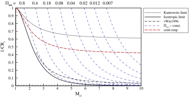
2.6 Kantrowitz diagram for1/CRiandCRialong with isentropic limit and empirical relations. 39 3.1 Schematic of flow across a normal (left) and oblique shock (right). . . 42
3.2 Schematic of classical Busemann flow. . . 43
3.3 Sketch of characterstic mesh along with streamline traced contour (left) and close-up of three points (right). . . 45
4.1 Flow chart of design steps of the three-dimensional intake generation tool. . . 52
4.2 Control volume of figure 2.2 reprinted for analysis of truncated portion of Busemann intake. . . 55
4.3 Schematic of streamline tracing within a compression flow field. . . 56
4.4 Different perspectives of streamline traced Busemann intake; geometry designed for M∞= 8,Πst= 45,δ = 3 deg. . . 56
4.5 Mach number contour plots of the streamline traced Busemann intake for the analytical (left) and Euler solution (right); geometry designed forM∞= 8,Πst= 45,δ= 0. . . . 57
4.6 Probability density function and cumulative distribution function of the Berkowitz data set, along with analytical function,tp(A). . . 58
4.7 Displacement thicknesses for different boundary layer states along with edge pressure distribution plotted against the free stream distance (Tw= 500 K). . . 59
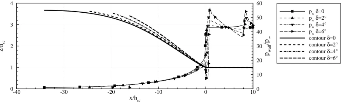
4.8 Wall pressures of leading edge truncated Busemann intake, designed forM∞= 8,Πst= 43,δ= 4 deg. . . 60
5.1 Kantrowitz plot with empirical starting relation, that allows adjustment viaC1-constant. . 63
5.2 Schlieren images of started and unstarted 3D-GRK intake flow along with sketched shock positions and possible separation region in internal flow path. . . 63
5.3 Sketch of various diffuser flows. . . 64
5.4 Kantrowitz plot with lines of constant total pressure and semi-empirical limit. . . 65
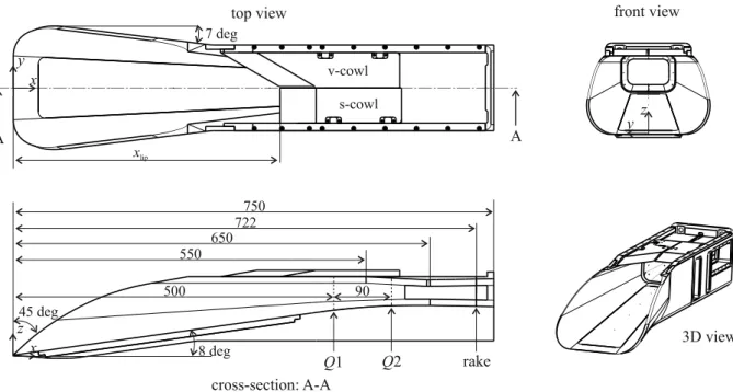
6.2 Internal contraction ratio, plotted against the distance from the intake leading edge to the cowl closure location. . . 67 6.3 Top and cross sectional view of intake configuration along with throttle and wind tunnel
mount. . . 68 6.4 Different perspectives of the streamline traced intake ST1; dimensions are in millimeter. 69 6.5 Different perspectives of the streamline traced intake ST2; dimensions are in millimeter. 69 6.6 Mach number contour plot extracted from axisymmetric CFD simulation for ST3
con-figuration. . . 71 6.7 Different perspectives of the streamline traced intake ST3; dimensions are in millimeter. 71 6.8 Schematic set-up of the H2K wind tunnel (left) along with characteristic diagram (right). 72 6.9 Rake with pitot and static pressure tubes. . . 73 6.10 Schematic of double-pass schlieren apparatus used during H2K wind tunnel experiments. 74 6.11 Settling chamber and throttle as attached to the 3D-GRK intake model to measure mass
flow and simulate back pressure. . . 75 6.12 Starting mesh for 3D-GRK intake configuration. . . 76 6.13 Starting mesh for axisymmetric Busemann intake configuration. . . 77 6.14 Influence of mesh size on pressure and temperature in intake exit plane atx= 0.722 m. . 78 6.15 Influence of mesh size on pressure in axisymmetric SCRamjet configuration. . . 78 6.16 Sample intake exit plane. . . 81 7.1 Mach number contour plot extracted from CFD for4 degleading edge truncation. . . 84 7.2 Busemann intake contours along with wall pressure plots for increasing leading edge
truncation; all intakes designed forM∞= 8andΠst = 43. . . 84 7.3 Cross-stream pressure and Mach number of leading edge truncated Busemann intakes at
outlet plane; all intakes designed forM∞= 8andΠst= 43. . . 85 7.4 Mass- and stream-thrust-averaged parameters and maximum temperature of leading edge
truncated Busemann intakes; all intakes designed forM∞= 8andΠst = 43. . . 85 7.5 Reversed nozzle intake contours along with wall pressure plots for increasing leading
edge truncation; all intakes designed forM∞= 8andΠst = 43. . . 86 7.6 Cross-stream pressure and Mach number of leading edge truncated reversed nozzle
in-takes at outlet plane; all inin-takes designed forM∞= 8andΠst = 43. . . 87 7.7 Mass- and stream-thrust-averaged parameters and maximum temperature of leading edge
truncated reversed nozzle intakes; all intakes designed forM∞= 8andΠst= 43. . . 87 7.8 Mach number contour plot extracted from CFD for largest amount of rear side truncation. 88 7.9 Busemann intake contours along with wall pressure plots for increasing rear side
trunca-tion; all intakes designed forM∞= 8, δ= 0, andΠst= 43. . . 89 7.10 Cross-stream pressure and Mach number of rear side truncated Busemann intakes at
outlet plane; all intakes designed forM∞= 8, δ= 0, andΠst= 43. . . 89 7.11 Mass- and stream-thrust-averaged parameters and maximum temperature of rear side
truncated Busemann intakes; all intakes designed forM∞= 8, δ= 0, andΠst= 43. . . 90 7.12 Reversed nozzle intake contours along with wall pressure plots for increasing rear side
truncation; all intakes designed forM∞= 8, δ= 0, andΠst= 43. . . 91 7.13 Cross-stream pressure and Mach number of rear side truncated reversed nozzle intakes
at outlet plane; all intakes designed forM∞= 8, δ= 0, andΠst= 43. . . 91 7.14 Mass- and stream-thrust-averaged parameters and maximum temperature of rear side
truncated reversed nozzle intakes; all intakes designed forM∞= 8, δ= 0, andΠst= 43. 92 7.15 Busemann intake contours for Mach 8 case with and without viscous correction. . . 93 7.16 Normalized pressures for Mach 8 Busemann configurations with and without viscous
List of Figures
7.17 Normalized pressures extracted from Busemann intakes for various Mach numbers
plot-ted againstx-coordinate. . . 94
7.18 Reversed nozzle contours for Mach 8 reference case with and without viscous correction. 95 7.19 Normalized pressures for Mach 8 reversed nozzle configurations with and without vis-cous correction plotted againstx-coordinate. . . 95
7.20 Normalized pressures extracted from reversed nozzle flows for various Mach numbers plotted againstx-coordinate. . . 96
7.21 Geometry overview of Busemann and reversed nozzle geometry for Mach8condition. . 97
7.22 Intake performance parameters for leading edge truncation. . . 97
7.23 Intake performance parameters for rear side truncation. . . 99
7.24 Intake performance parameters for Mach number variation. . . 100
7.25 Intake performance parameters for leading edge truncation with viscous correction. . . . 102
7.26 Wall pressure, averaged pressure, and Mach number contour plot extracted from CFD for ST1 intake configuration for on-design condition. . . 104
7.27 CFD-schlieren plot and averaged variables extracted from internal portion of ST1 intake configuration for on-design condition. . . 104
7.28 Normalized pressure on cross sectional planes of ST1, ST2, and ST3 configuration for Mach 8, extracted from CFD atx= 0.722 m. . . 105
7.29 Wall pressure, averaged pressure, and Mach number contour plot extracted from CFD for ST2 intake configuration for on-design condition. . . 106
7.30 CFD-schlieren plot and averaged variables extracted from internal portion of ST2 intake configuration for on-design condition. . . 106
7.31 CFD-schlieren plot and averaged variables extracted from internal portion of ST2 intake configuration for Mach 7 off-design condition. . . 108
7.32 CFD-schlieren plot and averaged variables extracted from internal portion of ST2 intake configuration for Mach 6 off-design condition. . . 108
7.33 Normalized pressure on cross sectional planes of ST2 configuration for different Mach numbers, extracted from CFD atx= 0.722 m. . . 109
7.34 Wall pressure, averaged pressure, and Mach number contour plot extracted from CFD for ST3 intake configuration for on-design condition. . . 110
7.35 CFD-schlieren plot and averaged variables extracted from internal portion of ST3 intake configuration for on-design condition. . . 110
7.36 Starting behavior for different free stream Mach numbers and different cowl geometries. 111 7.37 Schlieren images of unstarted, started, and plateau case forM∞ = 7and the v-shaped cowl configuration. . . 112
7.38 Influence of pitch angle (α) variation on starting behavior of intake; yaw angle was kept zero. . . 113
7.39 Influence of yaw angle (β) and of simultaneous pitch and yaw angle on intake starting for v-shaped lip at Mach7. . . 114
7.40 Self-starting limits of the 3D-GRK intake configurations plotted in the Kantrowitz diagram.115 7.41 Self-developed semi-empirical relation in comparison with self-starting intake configu-rations plotted in the Kantrowitz diagram. . . 115
7.42 Intake exit pressure, averaged at rake, plotted against throttle ratio (throttle closed for increasing throttle ratio) for the three different self-starting configurations. . . 116
7.43 Measured captured mass flow and intake exit velocity for different intake configurations. 117 7.44 Close-up of captured mass flow and intake exit velocity for Mach6configuration. . . 118
7.45 Numerical and experimental results of Mach7, v-cowl configuration. . . 118
7.46 Numerical and experimental results of Mach7, s-cowl configuration. . . 119
7.48 Static and pitot pressure, as well as Mach number for the Mach7, v-cowl configuration,
atx= 0.722 m. . . 120
7.49 Static and pitot pressure, as well as Mach number for the Mach7, s-cowl configuration, atx= 0.722 m. . . 121
7.50 Static and pitot pressure, as well as Mach number for the Mach6, v-cowl configuration, atx= 0.722 m. . . 121
7.51 Normalized pressure on cross sectional planes, extracted from CFD atx= 0.722 m. . . 122
7.52 Geometrical overview of streamline traced intakes and v-cowl 3D-GRK intake. . . 123
7.53 Stream-thrust-averaged variables for 3D-GRK and streamline traced intakes, extracted for Mach8; data for internal portion of intakes. . . 125
7.54 Specific impulse from figure 1.2 replotted along with various intake configurations and close-up near Mach8region of streamline traced intake configurations. . . 126
A.1 Influence of mesh size on wall pressure. . . 136
A.2 Influence of mesh size on average pressure (left) and average temperature (right). . . 136
A.3 Axisymmetric Busemann contour plots without truncation. . . 137
A.4 Axisymmetric reversed nozzle contour plots without truncation. . . 138
A.5 Normalized temperature on cross sectional planes of ST1, ST2, and ST3 configuration for Mach 8, extracted from CFD atx= 0.722 m. . . 139
A.6 Mach number on cross sectional planes of ST1, ST2, and ST3 configuration for Mach 8, extracted from CFD atx= 0.722 m. . . 139
A.7 Normalized temperature on cross sectional planes, extracted from CFD atx= 0.722 m. . 140
A.8 Mach number on cross sectional planes, extracted from CFD atx= 0.722 m. . . 140
List of Tables
1.1 Overview of the HIFiRE flights. . . 27 6.1 Approximate mesh sizes for three-dimensional and axisymmetric cases. . . 77 7.1 Design parameters for leading edge truncated Busemann intakes withp3-adjustment; all
intakes designed forM∞= 8andΠst= 43. . . 84 7.2 Design parameters for leading edge truncated reversed nozzle intakes withp3-adjustment;
all intakes designed forM∞= 8andΠst= 43. . . 86 7.3 Design parameters for Busemann intakes truncated at their rear-side; all intakes designed
forM∞= 8, δ= 0, andΠst = 43. . . 88 7.4 Design parameters for reversed nozzle intakes truncated at their rear-side; all intakes
designed forM∞= 8, δ= 0, andΠst= 43. . . 91 7.5 Design parameters for Busemann intakes with viscous correction; all intakes designed
forΠst= 43and flight along constant dynamic pressure trajectory. . . 94 7.6 Design parameters for reversed nozzle intakes with viscous correction; all intakes
de-signed forΠst= 43and flight along constant dynamic pressure trajectory. . . 96 7.7 Stream-thrust-averaged data extracted from CFD at intake throat (x= 0.65 m) compared
to tool predictions for ST1, ST2, and ST3 on-design conditions. . . 104 7.8 Overview of investigated angle of attack configurations. . . 113 7.9 Captured mass flow for different configurations measured with attached throttle. . . 117 7.10 Mass capture ratios for various intake configurations; data extracted from CFD for flight
conditions. . . 124 A.1 Overview of different flight conditions along a trajectory with constant dynamic pressure
(q∞= 0.53 bar). . . 131
Nomenclature
A area m2
a speed of sound m/s
cf friction coefficient
cH Stanton number,α/cp/ρ/v
cp specific heat at const. pressure J/kg/K
cv specific heat at const. density J/kg/K
CR contraction ratio
D diameter m
e specific internal energy m2/s2
eν, fν, gν auxiliary variables
F, ~F force, force vector N
g gravity constant N/kg H shape factor h altitude, height m h specific enthalpy m2/s2 I specific impulse s k thermal conductivity J/s/m/K L length m
LHV lower heating value J/kg
ˆ
m mass ratio
˙
m mass flow rate kg/s
M Mach number,V /a
M CR mass capture ratio
~
n surface normal vector
p pressure N/m2
˙
Q heat flow J/s
˙
q specific heat flow J/s/m2
q dynamic pressure N/m2
R specific gas constant J/kg/K
R recovery factor
r radial coordinate m
Re Reynolds number,ρV x/µ
s Reynolds analogy factor
T temperature K tp transition parameter T R throttle ratio u, v, w x, y, zvelocity m/s U normalized velocity ~
v velocity, vector notation m/s
V absolute velocity=|~v| m/s
x, y, z spatial coordinates m
y+ non-dimensional wall distance
Z thickness parameter
α heat transfer coefficient J/s/m2/K
α, β pitch, yaw angle deg
β shock angle deg
γ ratio of specific heats
δ truncation angle deg
δ1 displacement thickness m
δ2 momentum thickness m
δ0.99 boundary layer thickness m
ϕ equivalence ratio
η efficiency
Θ temperature ratio
θ deflection angle deg
θ Busemann: angle of fan-like lines deg
θ Method of Characteristics: flow angle deg
µ dynamic viscosity kg/s/m
µ Mach angle deg
Π pressure ratio
ρ density kg/m3
τ shear stress N/m2
Ω sample variable
Subscripts
3 intake exit position
adj adjusted cc combustion chamber char characteristic cl cowl closure corr corrected d drag
e boundary layer edge location
emp empirical H hydraulic i internal portion i index variable isentr isentropic Kantr Kantrowitz KE kinetic energy m modified mav mass-averaged n normal direction norm normalized o overall portion p pressure portion pit pitot r radial direction rec recovery sp specific st static sta stream-thrust-averaged
Nomenclature stoi stoichometric t,tot total th throat trans transitional v viscous portion w wall
∞ free stream condition
Abbreviations
3D-GRK three-dimensional intake configuration of research training group
AoA Angle of Attack
AUS AUStralia
BM BuseMann
CAD Computer Aided Design
CFD Computational Fluid Dynamics
DLR German Aerospace Center
DNS Direct Numerical Simulation
EXP EXPerimental/EXPeriment
FC Flight Condition
H2K Hypersonic blow down wind tunnel at DLR Cologne
HIFiRE Hypersonic International Flight Research and Experimentation
inv inviscid
LES Large Eddy Simulation
LHV Lower Heating Value
M7v Mach7condition with v-shaped cowl
M7s Mach7condition with straight cowl
M6v Mach6condition with v-shaped cowl
MAV Mass AVeraged
MDO Multidisciplinary Design Optimization
MOC Method Of Characteristics
NASA National Aeronautics and Space Administration
NASP National AeroSpace Plane
PSI Pressure Systems Inc.
RANS Reynolds-Averaged Navier-Stokes
REST Rectangular to Elliptical Shape Transition
RV2 RechenVerfahren II – Walz’ integral method
revN reversed Nozzle
s-cowl straight cowl geometry
SST Shear-Stress Transport
SSTO Single Stage To Orbit
ST Streamline Traced
STA Stream-Thrust-Averaged
TR Throttle Ratio
TMK Trisonic wind tunnel at DLR Cologne
US United States
v-cowl v-shaped cowl geometry
VC Viscous Correction
vis viscous
Abstract
The Supersonic Combustion Ramjet (SCRamjet) engine is an efficient propulsion device for supersonic and hypersonic velocities. The SCRamjet uses air from the surrounding atmosphere for the combustion process and therefore no oxidizer has to be carried on board. Furthermore, with higher velocities the ram compression increases and no compressor stage with rotating parts is needed. Thus, at supersonic and hypersonic velocities the SCRamjet engine becomes more efficient when compared to rocket or jet engines. The present work focuses on the SCRamjet air intake which serves as the engine’s compressor and is a crucial component. More specifically different topics related to analytical intake design and to general performance characterization of three-dimensional SCRamjet intakes were examined.
First, an analytical intake design tool was developed. To start, an axisymmetric Busemann or reversed nozzle flow was truncated at the leading edge or rear end. The changes caused by the truncation were modeled analytically. Then, from the axisymmetric flow field, streamlines were traced to generate a fully three-dimensional geometry. Along the individual streamlines the boundary layer displacement thickness was calculated with an integral method. This served two purposes: First, the geometry was widened with the displacement thickness to counteract additional contraction by the viscous boundary layer. Second, friction drag was calculated. The analytical results of axisymmetric and fully three-dimensional configurations were validated with numerical simulations. Numerical results were within
3%and8%of the analytical predictions for inviscid and viscous flows, respectively.
Second, the starting behavior of hypersonic air intakes was investigated experimentally in a blow down wind tunnel with a three-dimensional intake model (3D-GRK) with planar surfaces. Influence of intake cowl, free stream Mach number and angle of attack on intake starting were investigated. The self-starting configurations were all within the critical region of the Kantrowitz diagram, where intake starting should not occur according to Kantrowitz theory. In particular, the straight cowl in comparison to the v-shaped cowl allowed for more overboard spillage, therefore improving the starting characteristics. The increase in free stream Mach number raised the internal contraction ratio, at which intakes were still self-starting. Angle of attack effects were twofold: On the one hand, for positive pitch angle and no yaw deflection, intake starting was enhanced. On the other hand, for negative pitch angle or yaw deflection, starting was delayed. The experimental data were used to develop correlations to better predict intake starting. The correlations were within the critical region of the Kantrowitz plot and agreed with the experimental data and with data collected from literature.
Third, the 3D-GRK intake was further investigated experimentally and results were compared to numeri-cal simulations. Experimental and numerinumeri-cal results agreed to within the uncertainty of the measurements and only minor displacements near regions with separated flow were detected. To simulate pressure peaks stemming from the combustion process a throttle was attached to the intake model. The intake behavior under back pressure was investigated and the captured mass flow was measured. Captured mass flow, operating pressure ratio, and maximum sustainable pressure ratio before unstart all decreased as free stream Mach number was lowered. The ratio of maximum sustainable pressure to operating pressure, however, was constant at around4:1. To yield performance parameters at flight condition, the numerical simulations were extrapolated to flight condition. During extrapolation, the change in performance was below2%, therefore practically negligible.
Finally, the performance of the 3D-GRK intake configurations was compared to performance of dif-ferent streamline traced intakes. The streamline traced configurations consisted of continuously curved surfaces, which generated portions of isentropic compression. The 3D-GRK intake, in contrast, consisted of planar surfaces, and its performance, i.e. compression efficiency or total pressure recovery, was there-fore lower. After post-processing with one-dimensional combustor and nozzle tools the streamline traced
configurations had specific impulses of about3200 s,2700 s, and2300 sfor free stream Mach numbers of6,7, and8, respectively. For the same Mach numbers specific impulse of the 3D-GRK configuration was approximately300 slower.
Kurzfassung – German Abstract
Der Supersonic Combustion Ramjet (SCRamjet)-Motor ist ein effizienter Antrieb für den Über- und Hy-perschallflug. Der SCRamjet nutzt Luft aus der Atmosphäre zur Verbrennung und muss daher keinen Oxidator mit sich führen. Weiterhin steigt die Staustrahlkompression mit höheren Geschwindigkeiten und eine Verdichterstufe mit drehenden Teilen ist nicht mehr nötig. Deswegen ist der SCRamjet im Über-und Hyperschallflug effizienter, verglichen mit Raketen- oder Strahltriebwerken. Die vorliegende Arbeit konzentriert sich auf den Lufteinlauf, welcher als Kompressor dient und eine wichtige Triebwerkskompo-nente ist. Im Detail wurden verschiedene Themen in Zusammenhang mit analytischer Einlaufauslegung und genereller Leistungscharakterisierung von dreidimensionalen Triebwerkseinläufen untersucht. Zuerst wurde ein analytisches Einlaufauslegeverfahren entwickelt. Dafür wurden zunächst axialsym-metrische Busemann- oder umgekehrte Düsenströmungsfelder an der Spitze oder am Heck gekürzt. Die Veränderungen, welche durch die Kürzung verursacht wurden, wurden analytisch modelliert. In dem axi-alsymmetrischen Strömungsfeld wurden dann Stromlinien verfolgt und eine dreidimensionale Geometrie erzeugt. Entlang jeder einzelnen Stromlinie wurde die Grenzschichtverdrängungsdicke mit einem Inte-gralverfahren berechnet. Dies hatte zwei Gründe: Erstens wurde die Geometrie mit der Verdrängungs-dicke geweitet, um der durch die Grenzschicht verursachten Kontraktion entgegenzuwirken. Zweitens wurde der Reibungswiderstand berechnet. Die analytischen Ergebnisse für axialsymmetrische und drei-dimensionale ("Streamline-Traced") Konfigurationen wurden mit numerischen Simulationen validiert. Die numerischen und analytischen Ergebnisse lagen in reibungsfreien Fällen nur maximal 3% und in reibungsbehafteten Fällen nur maximal 8% auseinander.
Als nächstes wurde das Startverhalten von Hyperschalleinläufen anhand eines dreidimensionalen Ein-laufmodells (3D-GRK) experimentell in einem Windkanal untersucht. Der Einfluss der Einlauf-Hauben-geometrie, der Anströmmachzahl und des Anstellwinkels auf das Startverhalten wurden untersucht. Die selbststartenden Konfigurationen lagen alle innerhalb des kritischen Gebiets des Kantrowitz-Diagramms, in welchem laut Kantrowitz Einläufe nicht selbststartend sein sollten. Die gerade Haube verursachte einen größeren Verlustmassenstrom im Vergleich zu der v-förmigen und verbesserte so das Startverhal-ten. Mit steigender Anströmmachzahl erhöhte sich die Innenkontraktion, bei der die Einläufe selbst-startend waren. Der Einfluss des Anstellwinkels war wie folgt: Das Starten wurde zum einen durch positive Nick- und Gierwinkel nahe Null verbessert, zum anderen durch negative Nick- oder Gierwinkel verschlechtert. Die experimentellen Daten wurden verwendet, um Korrelationen zu entwickeln, welche das Startverhalten besser vorhersagen können. Die Korrelationen lagen innerhalb des kritischen Gebiets des Kantrowitz-Diagramms und stimmten mit den experimentellen und aus der Literatur recherchierten Daten überein.
Weiterhin wurde der 3D-GRK-Einlauf experimentell näher untersucht und Ergebnisse wurden mit nu-merischen Simulationen verglichen. Experimentelle und numerische Ergebnisse stimmten innerhalb der Messungenauigkeit überein, wobei nur kleinere Verschiebungen in der Nähe von Ablösegebieten ex-istierten. Um Druckschwankungen aus einem Verbrennungsprozess zu simulieren, wurde eine Drossel an das Einlaufmodell angefügt. Damit wurden das Einlaufverhalten unter Gegendruck und der gefangene Massenstrom gemessen. Sowohl der Massenstrom, das Druckverhältnis als auch das maximal mögliche Druckverhältnis nahmen mit sinkender Machzahl ab. Das Verhältnis von maximal möglichem zu nor-malem Druckverhältnis hingegen war mit 4:1 in etwa konstant. Um Leistungsparameter bei Flugbe-dingungen zu ermitteln, wurden die numerischen Simulationen auf FlugbeFlugbe-dingungen extrapoliert. Die Extrapolation beeinflusste die Ergebnisse nur marginal (<2%).
Zuletzt wurden die Leistungsparameter des 3D-GRK-Einlaufs mit denen von Streamline-Traced (ST)-Einläufen verglichen. Die ST-Einläufe hatten kontinuierlich gewölbte Oberflächen, welche zum Teil
eine isentrope Kompression ermöglichten. Im Gegensatz dazu hatte der 3D-GRK-Einlauf ebene Ober-flächen und seine Leistung, d.h. die Kompressionseffizienz oder der Totaldruckrückgewinn, waren deswegen niedriger. Nachdem die Einlaufparameter mit eindimensionalen Brennkammer- und Düsen-auslegungsverfahren weiter analysiert wurden, ergaben sich für die ST-Einläufe spezifische Impulse von jeweils 3200 s für Mach 6, 2700 s für Mach 7 und 2300 s für Mach 8. Für die gleichen Machzahlen lagen die spezifischen Impulse des 3D-GRK-Einlaufs etwa 300 s niedriger.
1 Introduction
1.1 Framework – Research Training Group 1095
The current dissertation is embedded into the Research Training Group 1095 [112, 40], as the subproject A3 labeledDesign and Characterization of a 3D SCRamjet Inlet. The overall program objective was to investigate the SCRamjet engine as a possible propulsion system for future space transport applications. Therefore, three groups were built according to the following structure:
• Group A focused on the SCRamjet intake and flow phenomena related to it.
• Group B focused on the SCRamjet combustor and supersonic combustion process.
• Group C focused on the SCRamjet nozzle design as well as overall system aspects.
Apart from the German Aerospace Center, three universities participated in the Research Training Group, namely the RWTH Aachen University, the Technical University of Munich, and the University of Stuttgart, which had the lead in the program. The program started in the spring of 2005 and ended in 2014 with a closing symposium in March at the University of Stuttgart.
It should be noted that even though some groups worked more independently at certain institutions, in general there was a high need for collaboration throughout the program and therefore throughout the locations. To ensure this collaboration, workshops were held once a year, which allowed program members to present their current results and hold discussions regarding their program status. To increase the collaboration and the international attention, so calledSummer Schoolswere held sequentially at the four different institutions and recognized experts from the field of SCRamjet research were invited. The goal was twofold; to receive input from professionals via presentations on their current research, and to exchange opinions and perspectives during individual discussions amongst program members.
1.2 Supersonic Combustion Ramjet Engine
The present section gives a short overview of the SCRamjet engine in general as well as of possible applications that could benefit from it. Finally, important flight demonstrators are discussed.
1.2.1 General Description
A Supersonic Combustion Ramjet, or SCRamjet engine, is an air breathing jet engine for supersonic or hypersonic speeds. The same cycle phases – compression, combustion, expansion – are present as in conventional air breathing jet engines. However, since ram compression is sufficient no rotating compressor and thus no turbine are used. Therefore, SCRamjet engines are normally mechanically simpler compared to their lower speed counterparts such as the turbojet or turbofan engines. Their internal shape and the design of the flow path determine engine performance. At low Mach numbers ram compression is weak and thrust declines to insufficient levels. Therefore, supplementary devices, such as rocket engines or hybrid engine cycles, are needed to bring a SCRamjet aircraft to an adequate take over speed.
Figure 1.1 shows a sketch of a SCRamjet vehicle along with certain terminology. In contrast to con-ventional turbofan engines, the SCRamjet engine is highly integrated into the aircraft. The three main components are the air intake, the combustion chamber, and the exhaust nozzle. Incoming air is com-pressed by the contraction of the air intake and guided into the combustion chamber where, at supersonic
Air Intake Combustion Chamber Exhaust Nozzle Cowl Leading Edge Trailing Edge Fuel Injection Free Stream
Figure 1.1: Schematic cross section of SCRamjet engine along with certain terminology.
Rockets Turbo-Jet Ram-Jet SCRam-Jet M Isp [ s] 0 2 4 6 8 10 12 14 0 1000 2000 3000 4000 5000 6000 7000
Figure 1.2: Estimated maximum specific impulse for hydrogen combustion of various jet propul-sion systems; image adapted from [29].
speeds, fuel and air are mixed and burned. The exhaust gas is then accelerated through the nozzle. Minor components are the leading and trailing edges, or the intake cowl and fuel injection system.
Since SCRamjet engines use air from the atmosphere for combustion, no oxidizer has to be carried along, which reduces overall vehicle weight and increases efficiency. The specific impulse relates the engine’s thrustF to the amount of fuel consumedm˙fueland earth’s gravityg:
Isp=
F gm˙fuel
, (1.1)
and is a parameter to measure and compare engine efficiency [47, p.111]. In figure 1.2 estimated specific impulse is plotted against Mach number for different air-breathers as well as rocket engines. In contrast to rocket engines, which have a constant specific impulse,Ispof air breathing engines varies with Mach number and it is evident that especially for high supersonic velocities (>4) ram compression is superior compared to rocket or turbo-jet engines. Extensive literature with overviews of SCRamjet engine systems exists and can be consulted for further information [47, 28, 29, 91].
1.2 Supersonic Combustion Ramjet Engine
1.2.2 Fields of Application Access to Space
One field of application for SCRamjet engines are launch vehicles that lift payloads through the earth’s at-mosphere into low earth orbit. Since air breathing engines have considerably higher specific impulse and efficiency compared to rocket engines [47], a significant effort was made during the National Aerospace-Plane (NASP, 1983 – 1995) program to design a Single Stage To Orbit (SSTO) vehicle [11, 90] that was capable of running in SCRamjet mode for a certain Mach number range. However, the effort at the time was too large, partially due to the fact that multi stage to orbit has advantages over SSTO, but also due to SCRamjet technology not being advanced enough compared to rocket technology, and thus no flight vehicle was built. Nevertheless, the incentive of air breathing assisted space access is still an active field of research. Currently there are ongoing studies which investigate the replacement of the second stage of a multi-stage to orbit vehicle with an air breathing SCRamjet engine [81].
The present project and the entire research training group (section 1.1) are also embedded in the context of space access. Furthermore, AIAA’s International Space Planes and Hypersonic Systems conference that was held in 2015 for the twentieth time, features extensive discussion and research on SCRamjet systems as means for space access, underlining the wide interest in this topic.
Military Usage
A country’s military is most likely the first user of SCRamjet powered vehicles to operate on a regular basis. The increase in speed that aircraft gain by switching to ram powered operation is encouraged by the better efficiency of the ram engine cycle at higher Mach numbers. The SR71 blackbird, for example, had a ramjet flow path in addition to the turbojet engine, which was used in greater proportion with increasing Mach number. This led to a decrease in fuel flow rate from38,000to36,000pounds per hour while accelerating from Mach3.0to3.15, due to the more efficient ramjet cycle [65, p.119]. Furthermore, various applications of ramjet missiles [12] already exist, and an evolution to a SCRamjet powered missile would be a natural step. The interest and participation of the United States Air Force and other defense contractors in the X51A and the HIFiRE programs (section 1.2.3) support this argument, and it is noted that a substantial amount of military-featured research would be classified.
Hypersonic Transport
In the long term, the SCRamjet engine cycle will also be of use for the civil sector, by reducing travel times, most likely after a substantial amount of flight hours have been accumulated during operation in the previous two sectors. Among others the LAPCAT [102, 94], FAST 20XX [93], and HEXAFLY [103] programs investigate this topic.
1.2.3 Flight Demonstrators X43A
The X43A, or Hyper X vehicle (figure 1.3) is a SCRamjet flight demonstrator by the National Aero-nautics and Space Administration (NASA) and a direct descendant of the earlier NASP and X15 flight programs [78, 63]. It was developed in a Multidisciplinary Design Optimization (MDO) loop [18, 19] for hypersonic flight and was the first SCRamjet to deliver positive thrust and acceleration during a controlled flight. While the first flight attempt in 2001 failed, the second and third flight in 2004 were successful and achieved Mach numbers of6.83and9.68, respectively, making it the fastest air breathing vehicle to date.
The vehicle was air launched from a B52 bomber and further accelerated to hypersonic speed by a Pe-gasus rocket booster. After booster separation the intake cowl opened and hydrogen fuel was injected.
front view
side view external ramps
internal flow path
external nozzle
Figure 1.3: X43A sketch (http://www.dfrc.nasa.gov/Gallery/Graphics/X-43A/).
Figure 1.4: Artistic rendering of X51 vehicle along with booster and interstage (https://commons. wikimedia.org/wiki/File:X-51A_Waverider.jpg).
Silane was added to assure ignition and turned off once the engine started successfully. The SCRamjet flow path was two-dimensional and consisted of the external parts and inner portion in which combus-tion occurred. Dynamic pressure during flight was≈ 0.5 barand the fuel flow lasted for 10seconds. After engine shut-down post flight maneuvers were performed in which the vehicle made a controlled hypersonic glide.
X51A
The X51A vehicle (figure 1.4) is a flight demonstrator of the HyTech program, led by the United States Air Force, with support of various defense contractors [45]. It is a direct descendant of X43A, but uses hydrocarbon fuel and ethylene to support ignition. Also launched from a B52 bomber, it is accelerated by a booster to a take over speed of about Mach4.8. During operation, dynamic pressure was larger than for the Hyper X vehicle at≈1.0 bar[72, 73]. The vehicle airframe was derived from a wave rider geometry while the engine flow path, that was built by Pratt and Whitney Rocketdyne, was two-dimensional. Between 2010 and 2013 there were four flights, while malfunctions, often related to the fins and once to an unstart of the intake, occurred during the initial three. The final flight in May 2013 was fully successful and the vehicle accelerated from Mach 4.8 to5.1 during a 210seconds flight. Post flight maneuvers were performed to test hypersonic glide capabilities after engine shut down.
1.3 SCRamjet Intakes
Table 1.1: Overview of the HIFiRE flights; table adapted from [21].
HIFiRE # led by topic launch date
0 AUS Software development March 2009
1 US Transition measurements on cone March 2010
2 US SCRamjet combustor study April 2012
3 AUS Axisymmetry, ducted SCRamjet Sept. 2012
4 AUS/US Hypersonic glider maneuverability during sounding rocket flight
2017†
5 US Transititon on elliptical cone April 2012*
6 US Related to HIFiRE 4, but with SCRamjet flow path
(no combustion)
2017†
7 AUS/US Ethylene combustion in three-dimensional SCRam-jet flow path at Mach 7
March 2015*
8 AUS/US Sustained SCRamjet powered flight for 30seconds at Mach 7
2018† †
estimated launch dates; could be subject to change
*
flight attempt failed; will be repeated
HIFiRE
The Hypersonic International Flight Research and Experimentation (HIFiRE) program investigates key aspects of hypersonic flight and is a joint cooperation between the United States and Australia. It consists of nine flights, the first of which (HIFiRE 0) was launched in2009and the last of which (HIFiRE 8) is planned to be launched in 2018. As of 2016, this program is still on going. In table 1.1 the flights are summarized, and it can be seen that at the beginning of the program experiments focused on basic topics such as hypersonic transition [57, 55] or supersonic combustion [53]. Towards the end of the program experiments are deeper specialized on hypersonic maneuverability and SCRamjet engine demonstration leading to HIFiRE 8: a sustained SCRamjet powered flight with ethylene fuel for30seconds.
There are two main differences to the previous X43A and X51A programs: First, all flights are launched with sounding rockets, and therefore for the sustained SCRamjet flight an additional pointing maneuver is necessary to readjust the vehicle horizontally. Second, the SCRamjet flow path is three-dimensional, as can be seen from the streamline traced and Rectangular to Elliptical Shape Transition (REST) intakes, that are used for HIFiRE 6 and 7, respectively [17, 86].
1.3 SCRamjet Intakes
The SCRamjet intake serves as the compressor within its engine cycle while the intake shape is responsi-ble for the entire ram compression. The intake can be regarded as the component that increases pressure and temperature of the free stream to levels sufficiently high for combustion. Pressure and temperature of0.5 barand1000 Kare reported in the literature as a priori estimates for hydrogen combustion with air [47, 98]. Pressure mainly influences combustion time and temperature affects ignition delay [84]. Therefore, during intake design the focus is on minimizing total pressure losses and guaranteeing stable operation along the flight path.
subsequent components depend on its proper functionality. Furthermore, the intake is a scene to various flow phenomena, such as laminar-turbulent boundary layer transition, shock boundary layer interaction or leading edge heating, that partially make up their own fields of research. Since the intake shape needs to integrate itself into the aircraft’s geometry, usually a trade off has to be made between the optimum aerodynamic design, manufacturing restrictions, practicality, or the like. Various literature exists that gives different perspectives on the topics of supersonic diffusers [48, 24] and hypersonic intakes [13, 114].
1.3.1 Intake Design
If considering an intake as a black box, there are two interfaces. The first one is the interface to the free stream. It is dependent on variables such as Mach number and the dynamic pressure or altitude along a given trajectory and can usually be considered as given. The second one is the interface to the isolator and combustor section. The intake black box is enclosed by boundary conditions such as state of the intake wall or geometrical restrictions. The work of the intake designer is then to meet all requirements while maximizing intake efficiency and maintaining a high degree of flexibility.
A general distinction between two-dimensional and three-dimensional intakes can be made [14], while three-dimensional intakes have several advantages. First, they compress the flow field in all three di-mensions and thus usually have less wetted surface area per unit mass flow through the intake. Second, as reported in [95], they show superior performance characteristics, even at off-design conditions, when compared to optimized two-dimensional ramp intakes. Third, as reported by Hirschel [49, p.311] shock boundary layer interactions occurring in three-dimensional space are frequently more tolerable than in two-dimensional. He noted that two-dimensional flow separations, such as on airfoils, are often times un-steady, while three-dimensional flow separations, such as on delta wings, can be macroscopically steady. Finally, two-dimensional configurations are more sensitive to angle of yaw.
Furthermore, one can distinguish between an analytical intake design approach and a more practical one, such as a parameter study supported by CFD, as reported by previous researchers within the research training group [50, 84]. Note that nowadays experimental investigations come in to play at later moments, due to the better development of numerical tools and increased costs for wind tunnel operation and model manufacturing. Several arguments are in favor of the analytical design approach. First, once a design tool is developed, in a relatively short amount of time an intake performance overview becomes available due to the numerically less expensive analytical computations. Second, requirements from the combustion chamber or trajectory can directly be considered during the design. Third, the intake design tool can be embedded in overall engine tools to quickly perform engine optimized parameter studies. Finally, with an analytical approach one remains more flexible to late changes in requirements.
Due to the above reasoning and the requirement of a three-dimensional intake design within the research training group, the focus of the present work is on the development of an analytical design tool for three-dimensional hypersonic intakes. A detailed report with the present state status on analytical intake design is given in section 2.1. Nevertheless, the great amount of research in that topic and the advancement from two-dimensional intake flow paths during the X43A and X51A studies to three-dimensional SCRamjet configurations (HIFiRE 7 & 8), stress the importance of the approach.
1.3.2 Intake Performance Parameters
Understanding of intake characteristics and flow can be gained by various means. Via qualitative infor-mation, such as the shock structure within an intake, or a schlieren image acquired during a wind tunnel run, general trends can be observed and effects can be compared relative to each other. Furthermore, local information such as wall pressure distribution or pitot pressure measurements can be extracted to study certain effects in more detail. Finally, overall intake behavior is best described by one-dimensional parameters, which are usually extracted at the intake exit plane. Those performance parameters are very
1.3 SCRamjet Intakes
useful for two reasons. First, they quantify an intake’s performance and allow for a comparison between different intakes. Second, they serve as a common denominator when the intake component is tailored back into a SCRamjet engine system analysis. Intake performance parameters, for example, can serve as boundary conditions to the combustion chamber or can be further processed in one-dimensional tools to calculate overall engine efficiency and performance.
In the further context some intake performance parameters are summarized. According to Smart [99], static pressure ratio, or sometimes referred to as compression ratioΠst, is a so called capability parameter and describes the average pressure at the intake exit divided by free stream static pressure. A higher static pressure ratio increases combustion rate while ignition delay is less affected [84].
Static temperature ratioΘstdescribes average static temperature at the intake exit normalized with free stream static temperature. Static temperature and pressure ratio are strongly coupled and an increase in one will normally lead to an increase of the other.
Total pressure recovery or total pressure ratioΠtot is the average total pressure at the intake exit di-vided by free stream total pressure and is always<1due to shock and viscous losses within the intake flow. Total pressure recovery is a measure for the efficiency of the compression process. An increase in compression ratio will normally lead to a decrease in total pressure recovery.
Total temperature ratio Θtot relates total temperature at the intake exit and entrance and is a measure of heat transfer into or from the vehicle structure. For cooled intake wallsΘtot <1holds, while a first approximation ofΘtot ≈1can often be used as a practical assumption.
Mass capture ratioM CRrelates mass flow through the intake to the mass flow through the capture area. ThusM CR < 1indicates that an intake is spilling air and does not capture the full air stream. Mass capture ratio is an important parameter to calculate nominal thrust parameters.
The parameters above are sufficient for any engine cycle analysis. Nevertheless, the following parameters are important for a better understanding of the intake flow. Intake exit Mach number,Mex orM3, can directly be calculated from static and total temperature ratio.
Overall contraction ratioCRo is the capture area divided by the smallest cross sectional, or throat area of an intake. It is a geometrical feature rather than a performance parameter, but should always be given along with intake compression ratio. Similarly,internal contraction ratioCRiis the cross sectional area at the beginning of the internal portion of an intake, divided by the throat area. It is also a geometrical feature, but has great impact on the starting behavior of an intake and can be used to estimate starting characteristics via empirical or analytical relations.
Maximum sustainable static pressure ratio before intake unstartΠst,max is an important parameter to determine thresholds for stable intake operation.
Maximum static temperature ratio Θst,max at the intake exit plane has a strong influence on ignition delay [84], because hotter locations can trigger ignition. The difference between static and maximum temperature ratio can be regarded as a measure for flow non-uniformity.
Finally, with total pressure recovery and free stream Mach number another compression efficiency pa-rameter can be calculated, namelykinetic energy efficiency:
ηKE= 1− 2 (γ−1)M2 ∞ (Πtot) 1−γ γ −1 . (1.2)
The variableγ describes the heat capacity ratio of the fluid. Kinetic energy efficiency is less dependent on free stream Mach number than total pressure recovery.
The performance parameters above will frequently be used throughout the context of this work. The list does not claim to be complete and further information on intake performance quantification can be found in the literature [16, 114, 98].
Figure 1.5: SR71 aircraft (left – http://bilder.4ever.eu/luftfahrt/jagdflugzeug/ lockheed-sr-71-blackbird-155931) and Lockheed-Martin concept image of SR72 aircraft (right – http://www.extremetech.com/wp-content/uploads/2013/11/SR-72.jpg).
1.3.3 Intake Starting
The flow through a SCRamjet intake can either be subsonic or supersonic while the latter is the condition desired and is referred to as started intake flow. Intake starting behavior is a performance characteristic that attracts special attention during intake design. Not only is it important to successfully start an intake once a vehicle reaches take over speeds, it is also important to know the limitations and flight conditions that might unstart an intake. Figure 1.5 shows an image of the reconnaissance aircraft SR71 and a design concept of the follow-up aircraft SR72, that has not been built to this date. Note that the SR71 possessed two turbo ramjet engines, while the SR72 is proposed to contain SCRamjet cycles. However, the problem of intake starting occurs thereof independently. An unstarted intake not only causes a loss in thrust and introduces the complicated task of engine restart, but it can also affect the aerodynamic stability or operability when more than one engine is installed as seen in figure 1.5. The SR71 for example encountered severe handling problems once one intake unstarted [65], due to the other one causing a high yaw moment that had to be balanced by the rudder. Ultimately an intake unstart and fail to restart can even lead to a loss of the vehicle, as reported for one flight of the X51A [73].
Furthermore, great interest throughout the community has been present over the years, ranging from early work on supersonic diffusers [77, 56] to more recent studies that include empirical relations to predict intake starting [105, 99] and focus on three-dimensional geometries [54, 74]. A detailed report with present state status of starting mechanisms is given in section 2.3. Nevertheless, it is emphasized up front that starting behavior of three-dimensional intakes is still an open topic and that options to improve intake starting are still being investigated.
1.4 Objective of Current Work
The current work is encompassed by the design guidelines of the research training group, which were a flight at a Mach number and altitude of 8 and 30 km, respectively. For the chosen design point, static pressure and temperature were constant at1170 Paand226 K, respectively, and dynamic pressure, calculated via: q∞= 1 2ρ∞V 2 ∞, (1.3)
was0.53 bar. To yield a static pressure of0.5 barin the combustor, the intake design pressure ratio at Mach8 was43. No fore-body compression was considered and a central strut fuel injector was to be used at the combustion chamber entrance. Detailed flight conditions and derived wind tunnel conditions are listed in the appendix (section A.1).
1.4 Objective of Current Work
should be capable of generating an intake shape and analytically estimating intake performance. Fur-thermore, it should allow for a change in requirements or boundary conditions during a design process. If possible, CFD should be excluded from the design process to decrease the run time of the tool. Nev-ertheless, numerical simulations should be used for the validation of the analytical results.
Another objective was to better understand the performance characteristics of SCRamjet intakes and to develop a relation to better predict intake starting. Therefore, an already existing intake model, which was developed during the early phase of the research training group, should be further investigated ex-perimentally in the hypersonic wind tunnel H2K. The focus of the experimental work should be on the intake starting behavior. The impact of different variables on intake starting should be investigated and with the gained experience an analytical relation to predict intake starting should be developed. Further-more, experimental results should be compared with numerical simulations, to prove the applicability of the computational tools to three-dimensional SCRamjet intake configurations.
The final objective was to contrast the new design methodology to the one used for the already existing intake model. Furthermore, performance of the two classes of intakes should be compared relative to one another at the design point and at off-design conditions. In this context intake performance param-eters should be used in a one-dimensional engine analysis to determine overall efficiency and to better understand the influence of intake performance on the overall engine system.
This section presents an overview of the current literature. It first focuses on analytical intake design and then on experimental and numerical performance estimation. Finally, the topic of intake starting is discussed and reviewed.
2.1 Intake Design
Smart [96] analytically investigated two-dimensional ramp intakes for Mach numbers ranging from4−
10, via the oblique shock relations. The intakes represented on-design configurations and for a constant pressure ratio the total pressure recovery generally increased with the number of oblique shocks. Viscous effects were not taken into account. Häberle [44] designed a two-dimensional intake with boundary layer bleed using the oblique shock relations for the ramps on the external portion of the intake. The internal shape and the isolator were widened in the vertical direction to account for the boundary layer thickness. Regions between shocks within the isolator were modeled with the method of characteristics, while viscous effects were not captured analytically. The boundary layer bleed reduced the size of the separation region but had only minor influence on intake performance. A three-dimensional ramp intake was designed by Reinartz and Gaisbauer [83]. The intake flow was first investigated numerically to estimate performance parameters and suitable sensor locations for a subsequent wind tunnel model. The intake model was then complemented with a combustion chamber and nozzle. Subsequently, the full engine model was successfully tested in a short duration facility [40], in which ignition of the hydrogen-air mixture was accomplished.
Hohn [50] and Riehmer [84] designed a three-dimensional intake, which is also a subject of this study and is explained in greater detail in section 6.1.1, via a parameter analysis and the aid of Computational Fluid Dynamics (CFD). Various parameters of the three-dimensional contour were varied and the geometry was subsequently analyzed numerically to yield a performance estimate. A design loop was performed and finished once the required intake exit conditions were reached. No analytical performance estimate could be made, but practical constraints, such as intake length or exit shape, were successfully considered. Furthermore, Hohn [50] generated streamline traced intakes from existing tools and pointed out their advantages.
In the remainder of this section the general approach to three-dimensional intake design, with an ana-lytical performance estimate is given, along with selected specific approaches from the literature. The general four steps can be summarized as follows. First, a compression flow field, such as Busemann flow or reversed nozzle flow, needs to be calculated analytically. Second, because those flow fields are usually long and therefore heavy, they need to be truncated. Third, after placing a desired cross sectional shape in the flow field perpendicular to the free stream, streamlines can be traced that confine the outer hull of a three-dimensional intake geometry. Finally, because the flow fields mentioned above are valid for inviscid flow only, viscous effects need to be considered.
2.1.1 Compression Flow Field
The axisymmetric compression flow field is the core of the three-dimensional design approach. There are two options to describe it analytically. On the one hand there are the Taylor McColl equations that result in Busemann flow [23, 68], which consists of an isentropic compression and a conical shock at the intake exit. On the other hand there is the method of characteristics, which usually describes expanding nozzle flow [2] that is fully isentropic. The nozzle flow can be reversed to a compressing flow field, which is
2.1 Intake Design x z δ M 3
leading edge shock A ∞ M ∞ A cc conical shock
Figure 2.1: Top: Schematic of classical Busemann flow; bottom: Schematic of leading edge trun-cation effects on Busemann flow.
also referred to as reversed nozzle flow. The Taylor McColl equations and method of characteristics are described in greater detail in section 3. There is no definite tendency that favors one flow field over the other, and there are groups with a Busemann flow [116, 54, 106] or a reversed nozzle flow [92, 95] as the underlying compression flow field.
A Busemann flow field is used for the description of the following truncation and viscous effects, and it is shortly described via figure 2.1 (top). The free stream is isentropically compressed through lines of constant pressure, temperature, and Mach number (iso-lines) and the flow field is terminated by a single conical shock. Along the iso-lines, the velocity and its direction are known, and therefore the intake contour can be calculated by tracing one streamline up- or downstream. A deeper introduction to Busemann flow is given in section 3.2.1.
2.1.2 Truncation Effects
In the present work, truncation effects are divided into leading edge and rear side truncation effects. Generally, due to the truncation of the geometry, the intake shape is no longer similar to its non-truncated counterpart. Therefore, the flow fields will no longer be self-similar and the flow variables are different from the non-truncated, classical flow field. Consequently, for fixed design conditions, i.e.M∞andΠst, a truncated geometry’s shape does not fall onto a classical one.
Leading Edge Truncation
While Busemann and reversed nozzle intakes show excellent performance characteristics due to the isentropic compression, they tend to become excessively long, and therefore skin friction drag and weight increases. Furthermore, their compression starts gradually, and therefore a0 deginflow would have to be ensured. Since there are manufacturing limitations on how sharp the leading edges can be, and because a
0 degleading edge would be prone to flow separation at angle of attack, Busemann and reversed nozzle intakes are usually truncated at the leading edge. A schematic of a truncated Busemann flow is shown at the bottom of figure 2.1, and it is noted that the general effect is also valid for reversed nozzle flow. When truncating the flow field, an oblique shock forms at the leading edge. This oblique shock interferes with the iso-lines of the isentropic compression and travels down the isolator, while the compression efficiency decreases with increasing truncation. Furthermore, the outflow is no longer homogeneous. Usually, a trade-off has to be made between the benefit of isentropic compression or reduced skin friction while considering manufacturing restrictions and the expected range of angle of attack. Truncation angles between2 degand6 degare usually sufficient to reduce the intake length to an acceptable degree. The truncation effect was also investigated in a numerical study for inviscid flows by Zhao [118], up to truncation angles ofδ = 6 deg. Zhao reported that with increasing truncation angle, a stronger oblique


![Figure 4.6: Probability density function and cumulative distribution function of the Berkowitz data set [10], along with analytical function, tp(A); image from [38].](https://thumb-us.123doks.com/thumbv2/123dok_us/276145.2528397/64.892.96.735.154.386/probability-function-cumulative-distribution-function-berkowitz-analytical-function.webp)
![Figure 4.7: Displacement thicknesses for different boundary layer states along with edge pressure distribution plotted against the free stream distance (T w = 500 K); image from [38].](https://thumb-us.123doks.com/thumbv2/123dok_us/276145.2528397/65.892.206.735.158.349/figure-displacement-thicknesses-different-boundary-pressure-distribution-distance.webp)