Rail Defect Detection and Classification with Real Time Image
Processing Technique
Canan Tastimur1, Hasan Yetis2, Mehmet Karaköse3 and Erhan Akın4
1, 2, 3, 4 Computer Engineering Department, Firat University, Elazig, Turkey
1
[email protected], [email protected], [email protected], [email protected]
ABSTRACT
Rail defect detection has a great importance for railway transportation. Because faults on the rails cause to problems such as the cost, the disruption of transportation and the safety. In this study, based real-time video processing algorithm used Morphological feature extraction is recommended to detection defects on railroad. The rail is detected by applying Hough Transform and image processing techniques to rail images obtained from the real time camera. Features of the detected rail images are extracted with applying morphological operations and defected regions are identified. Headcheck, fracture, scour and undulation failures are detected through proposed method. And then the classification of defects is performed. In the classification step, Haar-like features based AdaBoost classifier is utilized. In this study, results with low uptime and high success rate are acquired by performing all steps of proposed algorithm to the images of rail taken under different lighting and direction.
Keywords: Rail Track Detection, Rail Defects, Defects Classification, Hough Transform, Morphological Operation.
1. INTRODUCTION
The railway transportation has a major significance in the world. It is required that the railways to be examined in more detail with the improved railroad technology. Contact measurement technique is used to detect failures in the rails obtain low sensitivity and low accuracy rate results [1]. So it remains insufficient about meeting the needs of today‟s advanced railway technology [2]. The failures upon rails with advanced railway technology is identified without contact [3].
In time, the ascending wears on the rails bring about the disruption of transportation security, the off-road accidents, the interruption of the harmony between the rails and the wheels [4]. Detection of most critical components for the safe operation of trains is important [5]. The analysis of the rail profile must be repeated at regular intervals in order to prevent these situations and detect early failures that can occur in rail [6]. Nevertheless this process is costly and it needs that the railway track should be temporarily disabled [7].
The developed methods to detect failures in railway as contactless are available in literature. Shah [8], did work detection place and type of rail defect. He increased the quality of the image acquisition with controlled lighting and the use of superior computing power technology. Breakage failure in the rail is determined by following the block diagram. Block diagram of rail breakage failure detection in literature is shown in Figure 1.Vijaykumar and Sangamithirai [9], offered method that analysis the texture of rails through the help Gabor filter of various frequency and orientation. Defects were identified based on the size of the defects. However, rating of defects was not be accomplished with Gabor method of defect detection. Yaman [6], detected failures happened on the rail surface by associating images taken from two different cameras. The accuracy of proposed method was ascended by using the images taken from two different cameras.
Bettemir [10], which edges belongs to railway track was identified with Heuristic method by utilizing the geometric properties of the railway track and the brightness values of the edges. Shen et al. [11], inquired the feature extraction of the turnout defects based on the bogie acceleration measurement. The normal and faulty turnout model based on SIMPACK were established first. Then the acceleration signal was analyzed in time-frequency domain. Hu et al. [12], detected the heavy rail surface defects based on the mathematical morphology of multi-scale and dual-structure elements according to the characteristics of heavy rail surface defects, uneven brightness and noise. When compared with the traditional edge detection methods, Hu‟s method is superior.
classifiers algorithm to determine the fasteners was employed in this improved system.
Image Acquisition
Region of Interest Detection
Applying Gaussian Filter
Edge Detection
Region Growing Process
Labeling of The Faulty Regions Noise Cancellation
Fig. 1. Block diagram of rail breakage failure detection in literature [8].
Molodova et al. [15], developed an automatic method which use axle box acceleration (ABA) measurements on trains for detecting railway surface defects. Trinh et al. [16], investigated the rail surface defects and detected the rail by combining the speed information obtained from the GPS information and distance measurements with all the camera images obtained from the video stream before did data analysis and advanced data integration for the rail defect detection. Chen et al. [17], applied image processing techniques as image enhancement, noise cancellation, feature extraction and adaptive threshold to rail images for the rail surface defect detection.
In this study, rail detection process is primarily done on the rail images taken from the real time video camera. Then Headcheck, fracture, scour and undulation failures that are on the rail images are detected by using image processing techniques. The detected defect regions are classified bu using AdaBoost classifiers. The defect type of rail track surface is decided with classification. The recommended method of rail defects both runs faster than most algorithms in literature and detects stated all failures with a single algorithm.
2. RAIL DEFECTS
Failures in railway track can be expressed as wear, breakage, scour, undulation, headcheck and oxidation [18]. Horizontal and vertical wears occur in surface which rails contact with wheel. If the amount of rail wear is greater than 33 degree, the boden climbing occurs. So the rail is exchanged with new rail or
navigational restriction is made. Rail abrasions happen in horizontal curves, scissors languages and middle of scissors. Rail abrasions are divided into two as vertical and lateral wear. Vertical wear
is a wear shaped of spread and bending that occurs in the track mushrooms of the curve, middle of scissors and head rail of joints [18]. Whereas lateral wear occurs in the scissors languages and the inner cheeks of outer rail by the effect of the centrifugal force [18]. The rail fracture is deeper than 10 mm and longer than 50 mm space in the movement place of the rail [18].
Headcheck defect is found around the gauge corner of outer rail and this fault ascending inclines to happen when cracks reach 30 mm in surface length [20]. The undulation failure can be expressed that different collapses happen in the rail surface [18]. An example of undulation defect that can occur in the rail is shown in Figure 4. The scour fault that can happen in the rail is one or several places of the rail due to the spinning of the locomotive. It should be exchanged rails exceeding the amount scour [18]. An example of scour fault that can occur in the rail is shown in Figure 5. Rail oxidation is that crusting, decay, rust and small holes occur in the rail by effecting humidity, soil and water [18].
Earlier detection of rail defects is important for both preventing accidents that can happen and preventing greater than a costly problem.
Fig. 2. An example picture of the rail fracture [19].
Fig. 3. An example of headcheck failure that occur in the rail [20].
Fig. 5. An example of scour defect that can happen in the rail [20].
3. THE PROPOSED METHOD
Failures in railway track can be expressed as wear, breakage, scour, undulation, headcheck and oxidation. A contactless vision based image processing algorithm is recommended in order to detect and classify defects that can happen on the rail surface. The block diagram of rail defect detection and classification is shown in Figure 6.
Rail Track Images
Rail Defect Detection
Rail Defect
Classification Results
Fig. 6. The block diagram of the proposed method.
3.1 Rail Defect Detection Method
In first step of the proposed detection method, rail object is determined in railway image which is received from a camera placed on train. Then, the detected rail track is given to defect detection algorithm as a parameter to detect failures on the rail surface and the faulty regions on the rail surface is detected by being used image processing techniques.
The detection method of defects on the rail surface both runs faster and gets more correct results than contact measurement technique through utilizing the proposed method. Furthermore, damage doesn‟t occur on the rail surface during this process. The block diagram of the proposed detection method is shown in Figure 7.
Fig. 7. Block diagram of the proposed detection method.
The rail track image that is obtained from rail detection algorithm is given to the defect detection algorithm as a parameter. Then, preprocessing, feature extraction and
defect decision operations are performed. In the rail defect decision process, it is judged whether to be defective of the region by using area feature.
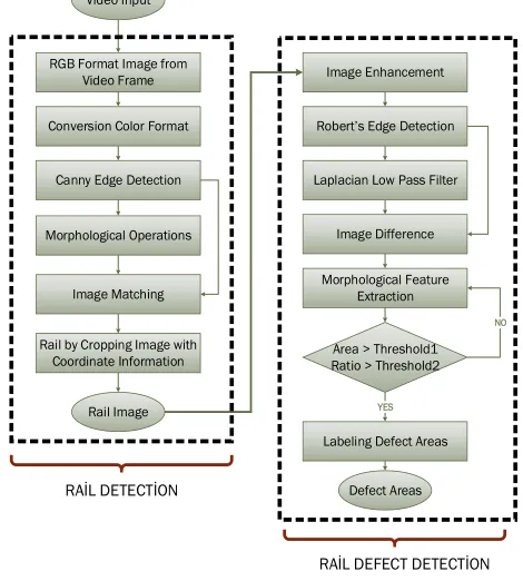
While in the adaptive block, exchange of the stated area threshold value is investigated. In this way, rail detection process, rail fault is detected more accurately and labeling of noisy areas as rail defect is prevented. Flow chart of this proposed detection method is shown in Figure 8.
RGB format images obtained from video frames are primarily converted to Grayscale format images in order to facility algorithm processes. Then image sharpening and Canny edge detection are performed to this image. It is subtracted the last image which the Morphology operations were implemented to from the image which the image sharpening and Canny edge detection were applied to. Thus the difference image is obtained by this subtraction operation. Background removal process is carried out by applied Morphology operations to the difference image [30]. The image whose background was removed has solely rail and some noises. The accuracy rate of rail detection is risen by the background removal operation. The Hough transform finds line segments on the image [21, 22]. Accordingly the line segments are determined by applying Hough Transform to the result image. So the rail object is detected with coordinate informations of the detected line segment.
Video Input
RGB Format Image from Video Frame
Conversion Color Format
Canny Edge Detection
Morphological Operations
Image Matching
Rail Image
Image Enhancement
Robert’s Edge Detection
Laplacian Low Pass Filter
Image Difference
Morphological Feature Extraction
Area > Threshold1 Ratio > Threshold2
Labeling Defect Areas
Defect Areas YES
NO Rail by Cropping Image with
Coordinate Information
RAİL DETECTİON
RAİL DEFECT DETECTİON
Fig. 8. Flow chart of the proposed detection method.
is performed in the defects detection algorithm. Rail defects are more prominent than previous appearance with applied the image sharpening and adjustment to the rail image. Then Robert‟s edge detection is enforced to the resulted image. Robert‟s edge detection basically finds vertical and horizontal edges on image [23]. In the next step, Laplacian low pass filter is applied to the rail image in order to extract limits of defect areas. Low pass filter removes high frequency information while tends to hold low frequency information. Laplacian filter finds to variation on the neighbor pixels. Laplacian low pass filter softens to the image by reducing disharmony between averaging nearby pixels and pixels values [24]. It is subtracted image applied Laplacian low pass filter from image applied Robert‟s edge detection in order to remove noise from the image. The difference image is image which this subtraction operation is applied to.
The feature extraction is applied to the difference image by carrying out morphology operations. Applied morphology operations are respectively bridge, close and fill. In this morphology operations, it is investigated statements that are connection to each other of the neighbor pixels, size of white and black pixels and whether gaps between pixels.
The morphology bridge operation provides significant faults to appear in the image. The morphology close operation enables the detection of any faults which are independent of one another and the morphology fill operation closes gaps between pixels. In the latest step, labeling of the fault regions is performed. In order to perform this, „Area‟ and „Ratio‟ features in Matlab are used. The ratio parameter is shown in Equation (1). The area and ratio parameters are used the separation parts of the limit and feature extraction of the region [25].
Ratio = MajorAxisLength ÷MinorAxisLength (1)
If „Area‟ value of the identified regional is greater than identified threshold value and „Ratio‟ feature is used to decision, this regional is labeled as defect. The area parameter can be expressed as total value of white pixels in white-black image which is applying image processing techniques. The ratio parameter can be expressed as ratio value of white pixels. In defect detection, accuracy rate was achieved higher results than a literature algorithm [26] with „Area‟ and „Ratio‟ features.
3.2 The Defect Classification Method
The AdaBoost classifier based on Haar-like features is utilized to classify defects of rail track. The detected rail defects are input parameters of the classification algorithm. The Haar-like features that are the most
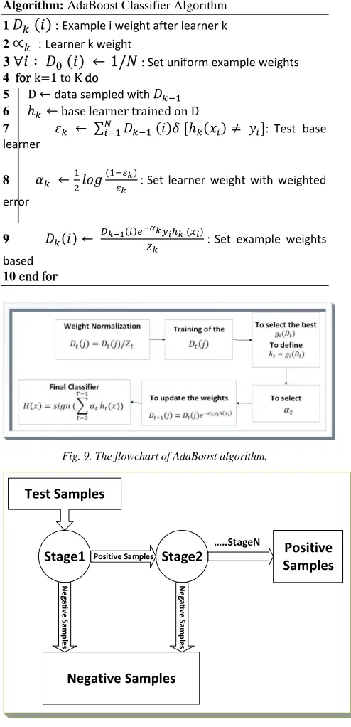
popular weak classifiers used with AdaBoost algorithm are consisted of several black and white rectangles [27]. The term of integral image was introduced to compute the sum of pixel value in black and white rectangles. The following pseudo code shows the execution of the proposed AdaBoost algorithm. The flowchart of AdaBoost algorithm is shown in Figure 9.
Algorithm: AdaBoost Classifier Algorithm 1
( )
: Example i weight after learner k2 : Learner k weight
3
( )
: Set uniform example weights 4 for k=1 to K do5 D data sampled with
6 base learner trained on D
7 ∑ ( ) ( ) : Test base learner
8 ( ): Set learner weight with weighted error
9 ( ) ( ) ( ): Set example weights
based
10 end for
Fig. 9. The flowchart of AdaBoost algorithm.
Test Samples
Stage1 Positive Samples Stage2
N
e
ga
tive
Sa
m
p
le
s
…..StageN Positive
Samples
Negative Samples
N
e
ga
tive
Sa
m
p
le
s
The strong classifiers are acquired after training [28]. Then using the AdaBoost algorithm, a set of single classifiers are utilized to establish a strong cascade classifier, as shown in Fig. 10. A cascade of classifiers is a degenerated decision tree where at each stage a classifier is trained to detect almost all objects of interest [29].
4. EXPERIMENTAL RESULTS
A computer which has Intel (R) Core (TM) i5-2400 M CPU, 2.5 GHz, 6.00 GB RAM and 64 bit operating system features is used to perform the proposed method. This algorithm is run on variable rail images. Resolution of camera placed on train is important parameter for defect detection process. The more resolution of camera is good, the more algorithm performance is high. Performance of three algorithms which are used in the proposed method is shown in Table 1.
Table 1: Performance of the rail detection and rail defect detection algorithms
Algorithm
Elapsed Time
(Sec)
Accuracy Rate
(%)
Rail Detection 0.57 84.80 Rail Defect Detection 0.04 94.73 Defect Classification 0.10 81.52
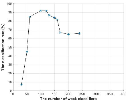
In this work, rail defect detection method is improved according to the previous work [26]. Accuracy rate of the defect detection is increased with adaptive block. Value of the area parameter is greater than previous work [26]. Thus both accuracy rate of the algorithm is enhanced and noisy areas of the image aren‟t labeled as defect areas. When the proposed detection method is compared with algorithm existed in literature, this algorithm is superior. Because this algorithm can detect with a single algorithm multiple faults. Moreover this algorithm is not affected from foreign objects which are existed around the rail track and from the reflection of sunlight. After detection of rail defects, these defect regions are subjected to the classification process. The classification process is performed in the OpenCV platform. The AdaBoost classifier algorithm is used to classify defect regions. The relationship between the classification rate and number of weak classifiers is shown in Figure 11. Experimental results of the rail track detection, the rail defect detection are respectively shown in Table 2 and Table 3.
Fig. 11. Relationship between classification rate and number of weak classifiers.
As seen in Figure 11, the classification rate of the AdaBoost algorithm with the increasing in the number of weak classifier does not always increase. Because the resulting is not correct classification. While the AdaBoost algorithm has reached the maximum classification rate with the increasing of the number of weak classifiers, the classification rate decreased. It is indicated that the AdaBoost algorithm can prevent from the deterioration fact. After the AdaBoost algorithm was trained, the output weight (αt) was computed for rail
defects classifier. The output weight is fairly straightforward. It is based on the classifier‟s error rate(et). et is the number of misclassifications over the
training set divided by the training set size. The relationship between error rate and the output weight is shown in Figure 12.
Fig. 12. Relationship between output weight and error rate.
Fig. 12 shows what αt will look like for classifiers with
are given exponentially more weight. The classifier weight grows exponentially negative as the error approaches 1.
Table 2: Experimental results of the rail track detection
Input Image Detected Rail
Track
Elap sed Time
(sec)
0.70
0.59
0.56
0.68
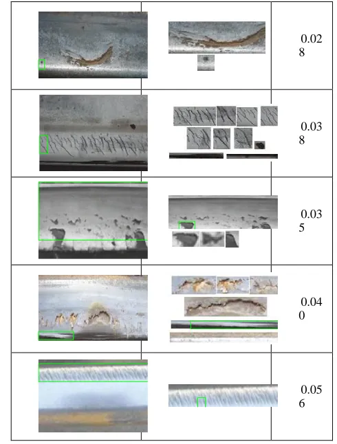
Table 3: Experimental results of the rail defect detection
Input Image Detected Rail
Defects
Elap sed Time
(sec)
0.04 1
0.03 5
0.03 0
0.03 2
0.02 8
0.03 8
0.03 5
0.04 0
0.05 6
5. CONCLUSIONS
phase. The proposed detection method was performed in Matlab and an average of 0.23 seconds and the average accuracy rate of 87% was obtained for each application by running rail input image.
ACKNOWLEDGMENTS
This work was supported by TUBİTAK (The Scientific and Technological Research Council of Turkey). Project Number: 114E202.
REFERENCES
[1] Y. Santur, M. Karaköse and E. Akın, “Learning Based Experimental Approach For Condition Monitoring Using Laser Cameras In Railway Tracks”, International Journal of Applied Mathematics, Electronics and Computers, Vol.4, pp. 1-5, 2016.
[2] I. Aydin, M. Karaköse and E. Akın, “Anomaly detection using a modified kernel-based tracking in the pantograph–catenary system”, Expert Systems with Applications, Vol. 42/2, pp. 938-948, 2015.
[3] M. Karaköse, İ. Aydın and E. Akın, “The Intelligent Fault Diagnosis Frameworks Based on Fuzzy Integral”, In IEEE Power Electronics Electrical Drives Automation and Motion Conference (SPEEDAM 2010), pp.1634-1639, 2010.
[4] M. Sun, Y. Wang, X. Zhang, Y. Liu, Q. Wei, Y. Shen and N. Feng, ”Feature selection and classification algorithm for non-destructive detecting of high-speed rail defects based on vibration signals”, In Instrumentation and Measurement Technology Conference (I2MTC) Proceedings, 2014 IEEE International, pp. 819-823, May 2014.
[5] L.F.M. Camargo, E. Resendiz, J. Hart, J.R. Edwards, N. Ahuja and C.P.L. Barkan, “Machine Vision Inspection of Railroad Track”, USDOT Region V Regional University Transportation Center Final Report, 2011.
[6] Y. Santur., M. Karaköse, E. Akin and I. Aydin, “IMU based adaptive blur removal approach using image processing for railway inspection”, In 2016 International Conference on Systems, Signals and Image Processing (IWSSIP), pp. 1-4, May 2016. [7] I. Aydin, E. Karaköse, M. Karaköse, M.T. Gençoglu,
E. Akin, “A new computer vision approach for active pantograph control”, In Innovations in Intelligent Systems and Applications (INISTA), 2013 IEEE International Symposium on, pp. 1-5, 2013.
[8] M. Shah, “Automated Visual Inspection/ Detection of Railroad Track”, Computer Vision Lab, Final Report, 2010.
[9] V. R. Vijaykumar and S. Sangamithirai, “Rail Defect Detection using Gabor filters with Texture Analysis”, In 2015 3rd International Conference on Signal Processing, Communication and Networking (lCSCN), pp. 1-6, 2015.
[10]Ö. H. Bettemir, “Rail Defect Detection using Gabor filters with Texture Analysis”, In Signal Processing and Communications Applications Conference (SIU), 2015 23th. IEEE, pp. 1366-1369, May 2015.
[11]L. Shen, X. Wei and L. Jia, “Surface Defects Detection of Railway Turnouts”, In Proceedings of the 34th Chinese Control Conference, Hangzhou, China, July 2015.
[12]G. Hu, L. Xiong and J. Tang, “Heavy Rail Surface Defects Detection Based on the Morphology of Multi-scale and Dual-Structure Elements”, In Chinese Automation Congress (CAC) 2015, pp. 2126-2129, 2015.
[13]M. Sun, X. Lin, Z. Wu, Y. Liu, Y. Shen and N. Feng, “Non-destructive Photoacoustic Detecting Method for High-speed Rail Surface Defects”, In Instrumentation and Measurement Technology Conference (I2MTC) Proceedings, 2014 IEEE International, pp. 896-900, 2014.
[14]Y. Li, H. Trinh, N. Haas, C. Otto and S. Pankanti, “Rail Component Detection, Optimization, and Assessment for Automatic Rail Track Inspection”, In Intelligent Transportation Systems, Vol.15, pp. 760-770, USA, 2013.
[15]M. Molodova, Z. Li, A. Núñez and R. Dollevoet, “Automatic detection of squats in railway infrastructure”, In IEEE Transcation on Intelligent Transportation Systems, Vol. 15, No. 5, October 2014. [16]H. Trinh, N. Haas, Y. Li, C. Otto and S. Pankanti,
“Enhanced Rail Component Detection and Consolidation for Rail Track Inspection”, In Applications of Computer Vision (WACV), pp. 289-295, Breckenridge, CO, 2012.
[17]L. Chen, Y. Liang and K. Wang, “Inspection of Rail Surface Defect Based on Machine Vision System”, In Information Science and Engineering (ICISE), pp. 3793-3796, China, 2010.
[18]Y. Santur, M. Karaköse, E. Akın, “Chouqet Fuzzy Integral Based Condition Monitoring and Analysis Approach Using Simulation Framework for Rail Faults”, In 14th IEEE International Conference on Industrial Informatics (IEEE INDIN 2016), Futuroscope-Poitiers, France, 18-21 July 2016. [19]G. Valenta, T. Varga and F. Loibnegger,
“Investigations of rail fractures at vienna underground and measures to reduce them”, In ECF13, San Sebastian 2000, February 2013.
[20]R.P.B.J. Dollevoet, Design of an Anti Head Check profile based on stress relief, University of Twente, 2010.
[21]Y. Liu and S. Zhou, “Detecting Point Pattern of Multiple Line Segments Using Hough Transformation”, In IEEE Transactions on Semiconductor Manufacturing, Vol. 28, No. 1, pp. 13-24, February 2015.
[23]M. Juneja and P.S. Sandhu, “Performance Evaluation of Edge Detection Techniques for Images in Spatial Domain”, In International Journal of Computer Theory and Engineering, Vol. 1, No. 5, 2009.
[24]R.C. Gonzalez and R.E. Woods, Digital Image Processing, Prentice Hall, Second Edition, 2002. [25]E. Rakun and M. Andriani, “Combining Depth Image
and Skeleton Data from Kinect for Recognizing Words in the Sign System for Indonesian Language“, In Advanced Computer Science and Information Systems (ICACSIS), pp. 387-392, 2013.
[26]C. Taştimur., E. Akın, M. Karaköse and I. Aydın, “Detection of rail faults using morphological feature extraction based image processing”, In Signal Processing and Communications Applications Conference (SIU), 2015 23th. IEEE, pp. 1244-1247, May 2015.
[27]S. Xiao, D. Li, H. Kunieda and T. Isshiki, “Design of an Efficient ASIP-Based Processor for Object Detection Using AdaBoost Algorithm “, In 7th International Conference on Information Communication Technology for Embedded Systems 2016 (IC-ICTES 2016,IEEE, 2016.
[28]X. Li, Q.X. Wu, Y. Kou, L. Hou and H. Xie, “Driver‟s Eyes State Detection Based on Adaboost Algorithm and Image Complexity”, In 2015 Sixth International Conference on Intelligent Systems Design and Engineering Applications, pp. 349-352, August 2015. [29]R. Lienhart, A. Kuranov, and V. Pisarevsky,
“Empirical Analysis of Detection Cascades of Boosted Classifiers for Rapid Object Detection”, In Joint Pattern Recognition Symposium, pp. 297-304, 2003. [30]H. Yetis, M. Karakose, “Adaptive Vision Based
Condition Monitoring and Fault Detection Method for Multi Robots at Production Lines in Industrial Systems”, International Journal of Applied Mathematics, Electronics and Computers, Vol.4, pp. 271-276, 2016.
AUTHOR PROFILES:
Canan Tastimur born in Elazig, Turkey, in 1991. She received B. S. degree in computer engineering from Firat University, Elazig, Turkey, in 2013. And she started the M. S. degree in computer engineering from Firat University, Elazig, Turkey, in 2014. She works as research assistant in the Computer Engineering Department, Engineering Faculty, Firat University, Elazig, Turkey. Her research interests are image processing, fault diagnosis, computer vision, railway inspection systems and fuzzy systems.
Hasan Yetis born in Malatya, Turkey, in 1992. He received B. S. degree in computer engineering from İnonu University, Malatya, Turkey, in 2014. And he started the M. S. degree in computer engineering from Firat University, Elazig, Turkey, in 2015. He works as research assistant in the Computer Engineering Department, Engineering Faculty, Firat University, Elazig, Turkey. His research interests are image processing, fault diagnosis, computer vision.
Mehmet Karakose received the B. S. degree in electrical engineering from Firat University, Elazig, Turkey, in 1998, the M. S. degree in computer engineering from Firat University, Elazig, Turkey, in 2001, respectively, and the Ph. D. degree in electrical engineering (computer engineering) from Firat University, Elazig, Turkey, in 2005. He is currently an associate professor doctor in the Department of Computer Engineering, Firat University, Turkey. He was a research assistant at Computer Engineering Department, Firat University from 1999 to 2005. His research interests include fuzzy systems, intelligent systems, simulation and modeling, fault diagnosis, computer vision, railway inspection systems, and photovoltaic systems. Assoc. Prof. Karakose is IEEE senior member.