5
IV
April 2017
Technology (IJRASET)
©IJRASET: All Rights are Reserved
568
Reversible Data Hiding In Image Transformation
Chetan G. Tappe1, A .V. Deorankar2
1
P.G. Student, Department of Computer Engineering, Govt. College of Engineering, Amravati, India
2
Associate Professor, Department of Information Technology, Govt. College of Engineering, Amravati, India
Abstract: In current years data hiding has been proposed as a likely technique for the purpose of information security. RIT-based on allows the user to convert the content of original image into the content of another target image with the same size. The transformed image, which looks like the target image, is used as the “encrypted image,” and is outsourced to the cloud. Therefore, the cloud server can easily embed data into the “encrypted image” If the receiver has both the data hiding key and the encryption key, can extract the additional data and recover the original content. Main objective of this paper to provide an efficient data hiding technique and image Encryption in which the data and image can be retrieving. Data concealment by Adaptive least significant bit replacement. Two RDH method including traditional use of block pairing and block transformation different needs on image quality.
Keywords
:
Embedded data, LSB, Reversible data hiding, Reversible image transformation, Secure communication.I. INTRODUCTION
The expanse of digital images has increased quickly on the Internet. Image security becomes gradually important for many applications, e.g., confidential transmission, video investigation, army and medical uses. For example, the requirement of fast and secure diagnosis is vital in the medical world. Nowadays, the transmission of images is a daily uses routine and it is necessary to find an effective way to transmit them over systems. To decrease the communication time, the data compression is necessary. The protection of this multimedia data can be done with encryption or data hiding processes. Since few years, a difficult is to try to combine compression, encryption and data hiding in a single step. For example, some solutions were suggested in to association image encryption and compression. Two main sets of technologies have been developed for this purpose. The main based on contented security through encryption. There are some methods to encrypt binary images or gray level images.
The next group bases the protection on data hiding, designed at secretly embedding a message into the data. Nowadays, a new task consists to embed data in encrypted images. Previous work recommended to insert data in an converted image by using an irrevocable process of data hiding or data hiding, intended at secretly embedding a message into the data. Unique data is to apply revocable data hiding processes on converted images by desiring to remove the embedded data before the image decryption. Newest irreversible data hiding techniques have been suggested with large size, but these approaches are not applicable on encrypted images.
Data security basically means protection of data from illegal users or hackers and providing high security to check data medication. This area of data security has gained more attention over the recent period of time due to the huge increase in data transmission rate over the network. In order to recover the security types in data transfers over the internet, many techniques have been developed like: Cryptography, Steganography. While Cryptography is a technique to secrete information by encrypting it to cipher texts and transmitting it to the intended receiver using an unknown key, Steganography provides further security by hiding the cipher text into a seemingly invisible image.
Technology (IJRASET)
©IJRASET: All Rights are Reserved
569
decoder. In divided the encrypted image into several blocks. By flipping 3 LSBs (least significant bits) of the half of pixels in each block, room can be vacated for the embedded bit. The data extraction and image retrieval proceed by finding which part has been reversed in one block. This process can be realized with the help of spatial association in the decrypted image. The cryptographer side by more misusing the spatial association using a dissimilar evaluation balance and side match system. For both methods in decrypting image and extracting data must be jointly executed. Recently proposed a novel RDH-EI method for joint decryption and extraction, in which the correlation of plaintexts is further exploited by distinguishing the encrypted and non-encrypted pixel blocks.
II. LITERATUREREVIEW
The reversibly embed the message into the host sequence by modifying its histogram with methods like histogram shifting [8] or difference expansion. Recently, Zhang et al. proposed the optimal histogram modification algorithm [4], for RDH by estimating the optimal modification probability.
Zhang divided the encrypted image into several blocks. By flipping 3 LSBs (least significant bits) of the half of pixels in each block, room can be vacated for the embedded bit. The data extraction and image recovery proceed by finding which part has been flicked in one block. This process can be recognized with the help of spatial association in the decrypted image. The decoder side by further exploiting the spatial correlation using a dissimilar estimation equation and side match technique. For both methods in [2] and [3], decrypting image and extracting data must be jointly executed.
Recently, Zhou et al. [5] proposed a novel RDH-EI method for joint decryption and extraction, in which the correlation of plaintexts is further exploited by distinguishing the encrypted and non-encrypted pixel blocks with a two-class SVM classifier. To separate the data extraction from image decryption, Zhang [7] emptied out space for data embedding by directly using the typical manner of cipher text compression that is, compressing the encrypted pixels in a lossless manner by using the syndromes of parity-check matrix of channel codes.
Recently Weiming Zhang, Hui Wang, Dongdong Hou, and Nenghai Yu propose a novel context [1], for RDH-EI based on reversible image transformation (RIT). Dissimilar from all preceding encryption-based frameworks, in which the encryption texts may attract the notation of the curious cloud, RIT-based context allows the user to transform the contented of original image into the content of another object image with the same size. The transformed image that looks like the target image is used as the “encrypted image,” Reversible data hiding in images is a technique that hides data in digital images for secret communication. It is a method to hide other missive into cover media with a revocable manner so that the innovative cover content can be perfectly restored after extraction of the hidden message.
The proposed method is inspired by Lai and Tsai [8], they first uses the concept of mosaic image in the field of information security. The type of mosaic image used by them is secret fragment visible mosaic image that is formed by dividing the source image into small tiles or block and arranging these blocks in random position with respect to target image. The target image is required to be selected from database. The database plays a vital role for mosaic image creation so for better result the database should be sufficiently large in size. For target image selection we have to scan the database in search of image with highest similarity measure with respect to given secret image. For this we have to divide the secret image into small tiles and calculate similarity measure for each block or tiles that is mean value of every block and randomly we have to select an image from database divide it into similar number of block as that of number of tiles of secret image and calculate mean value of each and every block then we have to compare mean values of secret image blocks with that of target image blocks to see whether at least 6 to 7 blocks values matches or not, if it doesn't match then we have to repeat the same procedure for another image from the database until we first the best fitted image.
A. Problem Definition
The problem found in our existing system as, the secret key used for encryption of compressed image and the data hiding is same .So, the user who knows the secret key used for encryption can access the data embedded and the original data. The original image can be retrieved from the encrypted image after extracting or removing the data hidden in the image. The content owner and the data hider share the same encryption key for the encryption of the image and data hiding. Main contented of the image is exposed already data mining. If someone has the data hiding key but not the encryption key he cannot extract any information from the encrypted image containing additional data.
III. PROPOSESYSTEM
Technology (IJRASET)
©IJRASET: All Rights are Reserved
570
owner encrypts the original uncompressed image using an encryption key to produce an encrypted image. Then, the data information wrappings the least significant bits (LSB) of the transformed image exhausting a data-hiding key to create a spare space to accommodate the additional data. At the receiver side, the data embedded in the created space can be easily retrieved from the encrypted image containing additional data according to the data-hiding key. Since the data inserting only marks the LSB, a decoding with the encoding key can result in an image similar to the original version. When using both of the encryption and data-hiding keys, the embedded additional data can be successfully extracted and the original
Fig.1.Propose system
the original image can be perfectly recovered by exploiting the spatial correlation in natural image. To implement Reversible Image Transformation technique to hide secure image into target image before storage. Improve the security of RIT framework using user defined pixel shuffling algorithms. And increase the hiding capacity of the image Data embedding using RDH technique. Data concealment by Adaptive least significant bit replacement technique. DES encryption is used because effective combination of speed, high security provided. The separable process gives original images and additional data separately.
IV. ARCHITECTUREOF RIT
As shown in fig.(2).Consist of following modules. First module in reversible image transformation of encoding. Next modules for reversible image transformation of decoding and final module of user modules. We will mainly elaborate of two modules in this section.
A. RIT-Encoding Module
1) RIT encoding means Reversible Image Transformation technique in which blocks of images will be transformed into blocks of
target image
2) At the time of encoding, system will split source and target images into parts
3) Source image parts will be shuffled with the help of SD values of pixels
4) The new sequence will be stored in the form of key
5) System will select pixel shuffling algorithm randomly
Technology (IJRASET)
©IJRASET: All Rights are Reserved
571
7) With the help of new positions, system will transform source image blocks into target image blocks
8) When all the blocks will be transformed, the combined image will be automatically formed.
B. RIT-Decoding Module
1) Decoding process is exactly reverse method of encoding
2) To decode source image, user will specify secrete key
3) If specified key is correct, user will be considered as authenticated user
Fig.2. Process of creating RIT.
4) With the help of that key , system will find out the shuffling algorithm
5) Using that algorithm, system will decode source image blocks
6) The source image blocks will be combined to get complete source image
7) System will get Sequence of the blocks from secrete key
V. REVERSIBLEIMAGETRANSFORMATIONMETHODS
Technology (IJRASET)
©IJRASET: All Rights are Reserved
572
A. Block Pairing
To make the transformed image J’ look like target image J, we hope, after transformation, each transformed block will have close mean and standard deviation (SD) with the target block. So we first compute the mean and SD of each block of I and J respectively.
Let a block B be a set of pixels such that B = {p1, p2, . . . pn}, and then the mean and SD of this block is calculated as follows:
(1)
2
(2)
When matching blocks between original image and target image, we hope two blocks with closest SDs to be a pair. In Lee et al.’s method, the blocks of original image and target image are sorted in ascending order according to their SDs respectively, and then each original block is paired up with a corresponding target tile in turn according to the order. To recover the original image from the transformed image, the positions of the original blocks should be recorded and embedded into the transformed image with an RDH method. If the image is divided into N blocks, N[logN] bits are needed to record block indexes. Obviously, the smaller the block size is, the better the quality of transformed image will be, but which will result in a large N. Therefore, the amount of information used to record the index for each block may be so large that it will cause much distortion when embedding these information into the transformed image. In fact there may not exist enough redundant space to store these additional information. For instance, if we divide a 1020 × 1020.
Fig.3. SD of 4x4 block for images.
Image into 4 × 4 blocks, 24× 16 bits are needed to record the positions of blocks. To compress the block indexes, we first classify
Technology (IJRASET)
©IJRASET: All Rights are Reserved
573
In this paper, we propose to divide both the original and target images into non-overlapping 4 × 4 blocks and calculate the SDs of
each block. We first divide the blocks of original image I into 2 classes according to the quantile of SDs. Denote that the %α
quantile of SDs by Nα .We assign the blocks with SDs ∈[0,Nα ] to “Class 0,” and blocks with SDs ∈(Nα,N100 ] to “Class 1.” And then we will scan the blocks in the raster order, i.e., from left to right and from top to bottom, and assign a class label, 0 or 1, to each block. Next, we label the blocks of target image based on the classes’ volumes of original image. Assuming that the i th class in the
original image includes ni blocks for i = 0 or 1, we scan the target image in the raster order, and label the first n 0 blocks with the
smallest SDs as Class 0, and the rest n1 blocks as Class 1. As a result, each class in the target image includes the same number of blocks as the corresponding class in the original image. We pair the original block up with target block in the following manner. Scan the original image and target image in raster order respectively and pair the jth block of the class i in the original image up
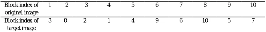
with the jth block of the class i in the target image for i = 0, 1 and j = 1, . . . , ni . A simple example on the proposed block pairing
method is shown in Fig. 3, in which the image only consists of 10 blocks. By setting α = 70, we assign 7 blocks with smallest SDs
into class 0, and the rest 3 blocks into class 1 in the original image. In the target image, although the 8th and 9th block have the same SD value 5, the 8th block is assigned to class 0 but the 9th block is assigned to the class 1, because class 0 can only include 7 blocks as determined by the class 0 of the original image. After labeling the class indexes, we get a class index table (CIT) for original image and target image respectively, which will be helpful for understanding the procedure of block pairing. According to the pairing rule, the first block of the original image is paired up with the forth block of the target image, because both of them is the first block of class 1 as shown in the CIT; the second block of original image is paired up with the ninth block of target image, because both of them is the second block of class 1, and so on. The pairing result is listed in Table I, which can be generated according to the CIT of original image and the CIT of the target image. For each pair of blocks (B, T), as we will see in the next section, the original block B will be transformed to target block T by mean shifting and block rotation, yielding T By replacing each T with T in the target image, the sender will generate the Transformed image. Note that both operations of mean shifting and block rotation will not change the SD value, so This the same SD as B. Therefore, position 3, and the second block should be put back to position 4 as indicated in Table I. Note that CIT can be efficiently compressed because the ratio of 0 and 1 is bias. If the
image is divided into N blocks, and these blocks are divided into two classes with % α quantile of SDs, we need N + H(α/100) bits
to record S, where H is the binary entropy function. For instance, if we set α = 75 and divide a 1020 × 1020 image into 4 × 4 blocks,
we only need 216 × H(0.75) ≈ 216 × 0.81 bits to record the positions of blocks, which is much less than 216 × 16 bits used by the
[image:7.612.98.504.458.619.2]method in. The compressed CIT will be encrypted and embedded into the transformed image as a part of AI.
Fig .4 Block pairing (a) Original image. (b) Target image. (c) Transformed image.
Table I Block Pairing Result Of Fig. 5 Block index of
original image
1 2 3 4 5 6 7 8 9 10
Block index of target image
[image:7.612.74.539.661.717.2]Technology (IJRASET)
©IJRASET: All Rights are Reserved
574
B. Block Transformation
By the block pairing method described above, in each pair (B, T), the two blocks have close SD values. Therefore, when transforming B towards T, we only need a mean shifting transformation that is reversible. However, the transformation used in Lee and Tsai’s method is not reversible because it changes the mean and SD at the same time.
Let the original block B = {p1, p2 ,… , pn }, and the corresponding target block T = {p1, p2 ,…,pn}. With Eq. (1), we calculate the
means of B and T and denote them by ub and ut respectively. The transformed block T = {p1, p2,…. , pn} is generatedby the mean
shifting as follows
(3)
where (uT − uB ) is the difference between the means of target block and original block. We want to shift each pixel value of
original block by amplitude (uT−uB) and thus the transformed block has the same mean with the corresponding target block.
However, because the pixel value pi should be an integer, to keep the transformation reversible, we round the difference to be the
closest integer as
(4)
and shift the pixel value by Δu, namely, each pi is gotten by
(5)
Note that the pixel value pi should be an integer between 0 and 255, so the transformation (5) may result in some overflow/
underflow pixel values. To avoid such transformed blocks abstained by (5), we assume that the maximum overflow pixel value is
OVmax for Δu ≥ 0 or the minimum underflow pixelvalue is UNmin for Δu <0. If overflow/underflow occurs insome blocks, we
eliminate them by modifying Δu
(6)
(7)
We use the modified Δu to shift the pixels of block B, and thus all the pixels’ values are controlled into the range of [0,
255].However the range of Δu’s value is still very large, which cannot be efficiently compressed. Thus we further modify Δu as in
which the quantization step, λ, is an even parameter. Then it just needs to record Δu = 2|Δu|/λ, by which it has the advantage of not
to record the sign of Δu. Because when Δu is an even number it means Δu ≥ 0 and when Δu is an odd number it means Δu < 0.
Since when λ is large the amount of informationrecording Δu will be small but the offset between themodified Δu and the original
Δu will be large, a tradeoff mustmade by choosing λ. We set λ = 8 in the following experiments.
Finally, to maintain the similarity between the transformed image and target image as much as possible, we further rotate the shifted
block into one of the four directions 0◦, 90◦, 180◦or 270◦. The optimal direction is chosen for minimizing the root mean square error
(MSE) between the rotated block and the target block. After shifting transformation and rotation, we get a new block T With these
new blocks, we replace the corresponding blocks in the target image and generate the transformed image J The parameters, Δu and
rotation directions, will be compressed, encrypted and then embedded into the transformed image J as AI to output the “encrypted
image” E(I) called in this paper image.
VI. RESULTANALYSISFORRIT
In this section experimental results on the proposed RIT method are presented. 100 pairs of images are randomly chosen as our test images from the Boss Base image database.2 Firstly all the images are preprocessed to get the same size of 1020 x 1020 pixels.
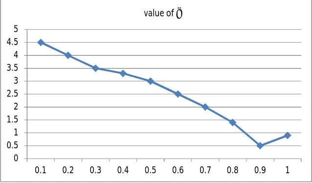
Since in the RIT method the parameter α has an effect on the AI payload, we give the experiment to select a better α to improve the
Technology (IJRASET)
©IJRASET: All Rights are Reserved
575
quality will be. For α in the range of [0.05,0.95], the variation of AI payload seems to be not large. And it can be seen that when α is 0.75, the AI payload reaches the valley value. So in the following experiments, α is set 0.75. To illustrate the visual effect of the RIT method, experimental results of five pairs of test images labeled as A, B, C, D and E are given. In Experiment A, we list the “decrypted images” with the right key and the wrong key respectively. Because the original image can be losslessly restored with the correct key, we did not list the “decrypted images” in the rest experiments. We also list the marked images with RDH in experiment D and E, which will be further discussed in the next section.
The encrypted images E(I) obtained by RIT look like mosaic images with their appearance similar to the target images. Since the difference between the encrypted image and the target image is small, such visual effect will meet the requirement of camouflage, which means that the original image content is totally covered by a target image content. Even if the attacker recognizes the camouflage, without the secret key K of AES, it is also unfeasible to decrypt the AI that is necessary for restoring the original image. And thus the attacker only gets a meaningless image.
The quality of the encrypted image E(I) is measured by the peak-signal-to-noise ratio (PSNR) defined as
(8)
where the MSE for an m x n image is computed by formula as given.
(9)
which xij and yij denote the pixel values of the target image J and encrypted image E(I), respectively. The result of five pairs of images listed is displayed. It can been seen that AI occupies about 0.521 bits per pixel (bpp) on average. Such large overhead cause large distortion to some extent, but the encrypted image E(I) still can keep an acceptable quality with the PSNR value about equal to 30 dB, which is an accepted visual effect. Besides we also give the average payload of AI and PSNR value of 100 randomly selected tested images, 0.529bpp and 27.2 dB respectively.
0 0.5 1 1.5 2 2.5 3 3.5 4 4.5 5
[image:9.612.138.457.435.622.2]0.1 0.2 0.3 0.4 0.5 0.6 0.7 0.8 0.9 1 value of α
Fig .6. Effect of AI payload of α value.
VII. CONCLUSION
Technology (IJRASET)
©IJRASET: All Rights are Reserved
576
The suggested method can take improvement of all modern RDH techniques for natural images and achieve excellent performance without loss of perfect secrecy. Moreover, this different technique can achieve existent reversibility, isolated data mining and impressively improvement on the quality of images.
REFERENCES
[1] Weiming Zhang, Hui Wang, Dongdong Hou, and Nenghai Yu propose a novel framework for RDH-EI based on reversible image transformation IEEE Trans on Multimedia, vol.18,no.8,aug 2016.
[2] W. Liu,W. Zeng, L. Dong, and Q.Yao, “Efficient compression of encrypted gray scale images,” IEEE Trans. Image Process., vol. 19, no. 4, pp. 1097–1102, Apr. 2010.
[3] X. Zhang, “Reversible data hiding in encrypted images,” IEEE Signal Process. Lett., vol. 18, no. 4, pp. 255–258, Apr. 2011.
[4] X. Hu, W. Zhang, X. Li, and N. Yu, “Minimum rate prediction and optimized histograms modification for reversible data hiding,” IEEE Trans. Inf. Forensics Security, vol. 10, no. 3, 653–664, Mar. 2015.
[5] W. Zhang, X. Hu, X. Li, and N. Yu, “Recursive histogram modification: Establishing equivalency between reversible data hiding and lossless data compression,” IEEE Trans. Image Process., vol. 22, no. 7, pp. 2775–2785, Jul. 2013.
[6] V. Sachnev, H. J. Kim, J. Nam, S. Suresh, and Y. Q. Shi, “Reversible watermarking algorithm using sorting and prediction,” IEEE Trans. Circuits Syst. Video Technol., vol. 19, 2009.
[7] X. Zhang, “ data hiding in encrypted image,” IEEE Trans. Inf. Forensics Security, vol. 7, no. 2, pp. 826–832, Apr. 2012.
[8] I. Lai and Wen. Tsai, “Secret-fragment-visible mosaic image-a new computer art and its application to information hiding,” IEEE Trans. Inf. Forensics Security, vol. 6, no. 3, pp. 936–945, Sep. 2011.
[9] W. Hong, T. Chen, and H. Wu, “An improved reversible data hiding in encrypted images using side match,” IEEE Signal Process. Lett., vol. 19, no. 4, pp. 199– 202, Apr. 2012.
[10] Y. Lee and W. Tsai, “A new secure image transmission technique via secret-fragment-visible mosaic images by nearly reversible color transformation,” IEEE Trans. Circuits Syst. Video Technol., vol. 24, no. 4, pp. 695–703, Apr. 2014.
[11] J. Tian, “Reversible data embedding using a difference expansion,” IEEE Trans. Circuits Syst. Video Technol., vol. 13, no. 8, pp. 890–896, Aug. 2003. [12] X. Hu et al., “Fast estimation of optimal marked-signal distribution for reversible data hiding,” IEEE Trans. Inf. Forensics Security, vol. 8, no. 5, pp. 779–788,
May 2013.
[13] W. Zhang, X. Hu, and N. Yu, “Optimal transition probability of reversible data hiding for general distortion metrics and its applications,” IEEE Trans. Image Process., vol. 24, no. 1, pp. 294–304, Jan. 2015.
[14] Y. Lee and W. Tsai, “A new secure image transmission technique via secret-fragment-visible mosaic images by nearly reversible color transformation,” IEEE Trans. Circuits Syst. Video Technol., vol. 24, no. 4, pp. 695–703, Apr. 2014..
[15] M. Johnson, P. Ishwar, V. M. Prabhakaran, D. Schonberg, and K. Ramchandran, “On compressing encrypted data,” IEEE Trans. Signal Process., vol. 52, no. 10, pp. 2992–3006, Oct. 2004.
[16] W. Hong, T. Chen, and H.Wu, “An improved reversible data hiding in encrypted images using side match,” IEEE Signal Process. Lett., vol. 19, no. 4, pp. 199–202, Apr. 2012.