A Compact Planar Inverted F Antenna Array
For Wireless LTE Portable Devices
Manish Kumar Soni1, Garima Saini2 1, 2
Department of Electronics & Communication Engineering, National Institute of Technical Teachers’ Training & Research Chandigarh, UT, India
Abstract: Multiple Input Multiple Output antenna systems have been the key reasons behind tremendous increase in speed with which data can be transferred through air. The focus area with these antenna designs has been to obtain small size with good performance of the system. In this paper a MIMO antenna system is proposed that is made up of two PIFA elements. The system is capable of operating in advanced LTE bands like LTE B 42, LTE B 43 and CBRS band. The design consists of two FR4 material substrate layers. The two planar radiating elements are placed on top of one substrate layer while the other substrate layer is kept at an air gap from first substrate layer. The ground plane is located on the bottom of the other substrate layer. The design is loaded with a pair of Rectangular Split Ring Resonator (RSRR) as metamaterial structure in between the space of two elements. The performance of loaded and unloaded designs is compared through simulation results obtained for both the designs. The dimensions of the array are only 45mm x 43mm x 7.9mm. The system resonates at 3.6 GHz with a bandwidth of 350 MHz from 3.38 GHz to 3.73 GHz. An isolation of more than -12.6 dB is achieved with the metamaterial loaded design. The MIMO performance analysis of the system is also done with the help of ECC (Envelope Correlation Coefficient), TARC (Total Active Reflection Coefficient) and Channel Capacity Loss.
Keywords: Planar Inverted F Antenna (PIFA); Long Term Evolution; Multiple Input Multiple Output; Total Active Reflection Coefficient; Envelope Correlation Coefficient; Channel Capacity Loss
I. INTRODUCTION
LTE (Long Term Evolution) operational range extends from 450 MHz to 3.8 GHz, which is divided in various frequency bands, called E-UTRA bands. Both types of techniques of communication i.e. Time Division Duplexing (TDD) and Frequency Division Duplexing (FDD) are supported by LTE. FDD works with a pair of frequencies per channel, which are separately assigned for both uplink and downlink. TDD, however, requires one frequency only per channel. In this technique, same frequency is shared between uplink and downlink in different time slots [1]. Advanced LTE bands like LTE B 42 (TD 3500), LTE B 43 (TD 3700) and Citizens Broadband Radio Services (CBRS) band offer high speed broadband services and are key bands on which future technologies may be built upon [2].
In recent times, MIMO platforms have been worked upon to reduce their dimensions in order to incorporate more antenna terminals on a single platform. The problem with the reduced size of the MIMO systems is the increase in mutual coupling between antenna terminals [3]. This interaction between electromagnetic radiation of the antenna elements lead to degradation in the performance parameters of the MIMO system [4]. Many performance enhancement techniques to improve the performance of closely spaced MIMO antenna elements systems have been proposed. These techniques include the use of defected ground structures, impedance transformers, neutralization lines, parasitic components etc. These techniques try to divert the direction of the surface current flowing on the antenna surface to reduce electromagnetic interaction between antenna elements [5], [6]. The disadvantages of above mentioned techniques are their complex geometry and comparatively large design.
Recently, a performance enhancement technique using metamaterial structures is being used in MIMO antenna systems to reduce the mutual interaction between elements and increase the overall performance of the system. Metamaterial are negative permeability material structures that offer imaginary propagation constant for surface electromagnetic waves and hence curtail them from propagating from one terminal to another. This results in a reduction in mutual coupling and an increase in the isolation [7]. This reduction in mutual coupling reflects on the performance of the MIMO system also with improved MIMO coefficients like TARC, ECC and Channel Capacity Loss.
MIMO system with PIFA elements is proposed but it has relatively less return loss and isolation in advanced LTE bands. In [10], a T-shaped structure is used to connect two identical PIFA elements. The structure works for ultra-wide band (UWB) applications. The disadvantage of this system is its small gain and large dimensions. In [11], a MIMO design with printed dipole is proposed with V-shaped ground branches. The gain of the system is limited only to 2.5 dBi which is very less for a MIMO system. In [12], an array of two PIFA elements is presented for LTE bands but the system does not perform well in terms of ECC and its size is also large. In [3]. A MIMO system with eight PIFA elements is presented but the ECC performance of the proposed system is not satisfactory.
The work which is presented in this paper is arranged as follows: Section II describes the MIMO performance parameters. Section III presents the selected design and its various parameters both for conventional and metamaterial loaded designs. Section IV shows the results obtained both for conventional and metamaterial loaded designs and finally, section V concludes the presented work.
II. MIMODESIGNPARAMETERS
Various Performance parameters for a MIMO design are Envelope Correlation Coefficient (ECC), Total Active Reflection Coefficient (TARC) and Channel Capacity Loss.
A. Total Active Reflection Coefficient (TARC)
It is the square root ratio of the reflected power from the antenna ports to the total incident power. For a MIMO system, only return loss does not have much significance. It is TARC, which is considered as overall return loss of the MIMO system. Even the bandwidth of a MIMO system is calculated from TARC curve. Just like return loss for a single element antenna, TARC should be as low as possible for a MIMO design. Mathematically it can be computed from complex scattering parameters as:
Where θ is the random input feed phase and it can have any value from 0 to π. It takes into consideration the mutual coupling between
antenna elements as well as random input signal phases [13]. Voltage Standing Wave Ratio (VSWR) of the MIMO system can also be calculated from TARC as:
B. Envelope Correlation Coefficient (ECC)
To determine the isolation between two antenna elements ECC is determined for a MIMO system. A lesser value of ECC signifies a higher isolation among elements and lesser mutual coupling. In practical MIMO designs, a value of less than 0.5 is considered good for ECC and hence is desirable for good MIMO system [13]. It can be computed from complex scattering parameters as:
C. Channel Capacity Loss (CCL)
Due to the presence of correlated environment in nature, the capacity of a MIMO system does not linearly increase with the number of radiating elements. The reason for this deviation is the losses that occur in the environment [13]. Channel Capacity Loss can be calculated for a 2x2 MIMO system, assuming that correlation is present in receiving antenna terminals only, as:
Where is the correlation matrix of receiver antenna and is given as:
(5)
; (6)
Where i,j = 1 or 2
III.ANTENNADESIGNCONFIGURATION
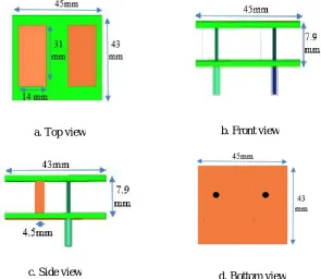
The design selected for the MIMO antenna is composed of two substrate layers of FR4 material. The two substrate layers are 5.9 mm air separated from each other. The FR4 substrate material used has relative permittivity of 4.4, thickness of 1 mm and a loss tangent of 0.02. The array of two elements is realized by superimposing the top substrate layer with two identical rectangular radiating elements of dimensions 14mm x 31mm. These two radiating elements are placed back to back with a separation of 11 mm
between them. Two separate 50 Ω coaxial cables are used to excite these radiating elements. To realize the PIFA geometry these
two radiating elements are shorted to the ground plane, which is located and printed on the bottom side of second substrate, with the help of two shorting plates of 4.5 mm width. The parametric analysis of the design is done in HFSS to realize the optimized dimensions that make the system resonates at 3.6 GHz. The positions of feed points are also optimized to get good impedance matching.
[image:4.612.164.459.256.512.2]The conventional PIFA MIMO design has been optimized to get smallest possible dimensions for the desired operation. The realized structure of this conventional MIMO design is as shown in Fig. 1.
Fig. 1. Conventional MIMO design a. Top View b. Front View c. Side View d. Bottom View
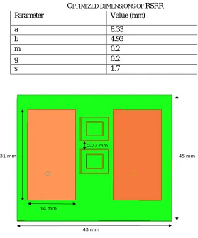
In order to reduce the mutual coupling and improve the MIMO performance characteristics of the design, a pair of RSRR structure is used as metamaterial in between the space of two radiating elements. The dimensions of RSRR are optimized in HFSS to improve the performance indicators of the MIMO array. The structure of RSRR and its optimized dimensions are shown in Fig. 2 and listed in TABLE I respectively.
Fig. 2. Structure of RSRR a. Top view
c. Side view
b. Front view
[image:4.612.199.431.598.716.2]When optimized Rectangular Split Ring Resonator structure is used in pair, the separation between its two units is optimized in parametric analysis to get improved performance of the resulting metamaterial loaded design. The top view of the RSRR pair loaded design is as shown in Fig. 3.
TABLE I
OPTIMIZED DIMENSIONS OF RSRR
Parameter Value (mm)
a 8.33
b 4.93
m 0.2
g 0.2
[image:5.612.160.439.128.463.2]s 1.7
Fig. 3. Top Geometry of design with a pair of RSRR
IV.SIMULATIONRESULTS
[image:5.612.143.451.554.718.2]Simulation of both conventional and improved PIFA MIMO arrays is done. The obtained results for both the designs are compared and analyzed for their respective MIMO performance. The designs are compared and analyzed in terms of return loss, mutual coupling, gain, TARC, ECC, VSWR and Channel Capacity Loss. Fig. 4 through Fig. 10 show comparison between conventional and improved designs in terms of these parameters graphically.
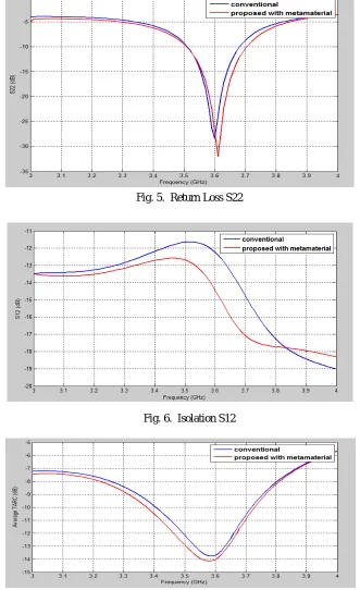
Fig. 4 compares the return loss for port 1 i.e. S11 for both designs. It can be seen that both designs resonate at desired frequency of 3.6 GHz. It can be observed that return loss for conventional design in -20 dB whereas it gets improved to -36 dB when metamaterial is used with the design. Similarly, Fig. 5 compares the return loss for port 2 i.e. S22 for both the designs. The conventional design has -28 dB return loss whereas the improved metamaterial design has -32 dB of S22. Fig. 6 shows the isolation between two elements of the array. In conventional array, isolation of more than -11.5 dB is observed for the frequency bands of interest whereas for improved design it attains a value better than -12.6 dB in the whole frequency band of interest.
Fig. 5. Return Loss S22
[image:6.612.132.463.174.716.2]Fig. 6. Isolation S12
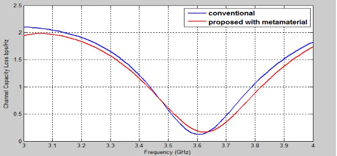
MIMO performance characteristics are plotted and compared in Fig. 7 through Fig. 10. Fig. 7 shows plot of average TARC for both the designs. For the conventional design the value of minimum TARC is -13.8 dB whereas it is -14.1 dB for the improved design. The average TARC for both the designs is always better than required -10 dB value in the advanced LTE bands. VSWR for both the designs are calculated from their respective TARC curves and are compared in Fig. 8. Channel Capacity Loss for both designs is depicted and compared in Fig. 9. For conventional design a minimum value of 0.15 bps/Hz is observed at 3.6 GHz. The value of capacity loss for the metamaterial loaded design is also well within 0.5 bps/Hz range for the desired frequency bands. In Fig. 10 evaluated ECC is plotted for both the designs. It can be seen that the ECC value reduces to zero in the desired bands for both the designs.
[image:7.612.133.462.189.365.2]Fig. 8. Average VSWR
Fig. 9. Channel Capacity Loss
[image:7.612.134.463.401.553.2]Fig. 11. 3D Gain Plot
TABLE III
COMPARATIVE ANALYSIS OF CONVENTIONAL AND PROPOSED DESIGN
Design Return Loss
S11 (dB) Return Loss S22 (dB) Isolation (dB) Minimum TARC (dB) Gain (dB)
Conventional -20 -28 > -11.5 -13.8 7.91
[image:8.612.118.495.86.408.2]Proposed -36 -32 > -12.6 -14.1 8.36
Fig. 11 depicts the 3D gain plot for the improved design. The comparative analysis of the improved PIFA MIMO array design is done with respect to conventional design in TABLE II. The parameters selected for the comparison are return loss, isolation, minimum TARC and gain. The size of both the designs is same with the dimensions of 45mm x 43mm x 7.9mm which amounts to a volume of 15286.5 cubic mm. These dimensions are smaller than already existing MIMO designs for identical applications. As the bandwidth of the MIMO design is calculated from the TARC curve, it can be seen from average TARC curve that the conventional design offers a 10 dB TARC bandwidth of 330 MHz compared to a bandwidth of 350 MHz for the improved design. The bandwidth for both the designs cover the desired advanced LTE bands.
V. CONCLUSIONS
This paper presents PIFA MIMO array capable of operating in advanced LTE bands for higher data rates. First, a conventional MIMO design is realized that operates in advanced LTE bands. The design is then used in conjunction with a pair of RSRR to enhance its performance parameters like gain, bandwidth, return loss, TARC etc. The dimensions of the metamaterial structure are optimized so that the performance of the conventional design is optimized. By using metamaterial structure with conventional design the gain enhances to 8.36 dB compared to 7.91 dB for conventional design. Isolation between elements also improve to better than -12.6 dB whereas it was limited to -11.5 dB for the conventional design. A minimum TARC of -14.1 dB is obtained for the improved design against a minimum TARC value of -13.8 dB for conventional array. Both the designs have good and almost identical MIMO performance characteristics like ECC of value nearly zero and Channel Capacity Loss of less than 0.5 bps/Hz. The size of both designs is same and is small compared to existing designs. Hence the proposed PIFA MIMO array is suitable to be employed for advanced LTE communication devices for high data rate communication.
REFERENCES
[1] B. Mun, C. Jung, M. J. Park and B. Lee, "A Compact Frequency-Reconfigurable Multiband LTE MIMO Antenna for Laptop Applications," IEEE Antennas and Wireless Propagation Letters, Vol. 13, pp. 1389-1392, 2014.
[2] M. M. Sohul, M. Yao, T. Yang and J. H. Reed, "Spectrum access system for the citizen broadband radio service," in IEEE Communications Magazine, Vol. 53, No. 7, pp. 18-25, 2015.
[4] Mustafa K. Taher Al-Nuaimi, “Mutual Coupling Evaluation of Dual-Miniaturized PIFA Antenna Array for MIMO Terminals,” European wireless conference 2011, pp. 618-621, 2011.
[5] S. Zhang, B. K. Lau, Y. Tan, Z. Ying and S. He, "Mutual Coupling Reduction of Two PIFAs with a T-Shape Slot Impedance Transformer for MIMO Mobile Terminals," IEEE Transactions on Antennas and Propagation, Vol. 60, No. 3, pp. 1521-1531, 2012.
[6] J. A. Ray and S. R. B. Chaudhuri, "A review of PIFA technology," 2011 Indian Antenna Week (IAW), Kolkata, pp. 1-4, 2011.
[7] Yalda Torabi, Ali Bahri and Ali-Reza Sharifi, “A Novel Metamaterial MIMO Antenna with Improved Isolation and Compact Size Based on LSRR Resonator,” IETE Journal of Research, Vol. 62, Issue 1, pp. 106-112, 2015.
[8] S. I. Jafri, R. Saleem, M. F. Shafique and A. K. Brown, "Compact reconfigurable multiple-input-multiple-output antenna for ultra wideband applications," IET Microwaves, Antennas & Propagation, Vol. 10, No. 4, pp. 413-419, 2016.
[9] S. Al Ja'afreh, Y. Huang and L. Xing, "Low profile and wideband planar inverted-F antenna with polarisation and pattern diversities," IET Microwaves, Antennas & Propagation, Vol. 10, No. 2, pp. 152-161, 2016.
[10] C. H. See, H. I. Hraga, J. M. Noras, R. A. Abd-Alhameed and N. J. McEwan, "Compact multiple input and multiple output/diversity antenna for portable and mobile ultra-wideband applications," IET Microwaves, Antennas & Propagation, Vol. 7, No. 6, pp. 444-451, 2013.
[11] H. Wang, L. Liu, Z. Zhang, Y. Li and Z. Feng, "A Wideband Compact WLAN/WiMAX MIMO Antenna Based on Dipole with V-shaped Ground Branch," IEEE Transactions on Antennas and Propagation, Vol. 63, No. 5, pp. 2290-2295, 2015.
[12] H. S. Singh, M. Agarwal, G. K. Pandey and M. K. Meshram, "A Quad-Band Compact Diversity Antenna for GPS L1/Wi-Fi/LTE2500/WiMAX/HIPERLAN1 Applications," IEEE Antennas and Wireless Propagation Letters, Vol. 13, pp. 249-252, 2014.