N A N O E X P R E S S
Open Access
Balanced Dipole Effects on Interfacial
Engineering for Polymer/TiO
2
Array Hybrid
Solar Cells
Fan Wu
1*, Yanyan Zhu
1, Xunheng Ye
1, Xiaoyi Li
1, Yanhua Tong
2and Jiaxing Xu
1Abstract
The polymer/TiO2array heterojunction interfacial characteristics can be tailored by balanced dipole effects through integration of TiO2-quantum dots (QDs) and N719 at heterojunction interface, resulting in the tunable photovoltaic performance. The changes ofVocwith interfacial engineering originate from the shift of the conduction band (Ec) edge in the TiO2nanorod by the interfacial dipole with different directions (directed away or toward the TiO2nanorod). The Jscimprovement originates from the enhanced charge separation efficiency with an improved electronic coupling property and better charge transfer property. The balanced dipole effects caused by TiO2-QDs and N719 modification on the deviceVocare confirmed by the changed built-in voltageVbiand reverse saturation current densityJs.
Keywords:TiO2, Array, Hybrid solar cells, Interfacial engineering
Background
TiO2 is mainly used in photocatalytic and
photoelec-trode for photocurrent because of its nontoxicity, high electron mobility, and high chemical and thermal stabil-ity [1, 2]. Hybrid solar cells (HSCs) based on conjugated conducting polymers (donor) and TiO2 nanocrystals
(acceptor) have received extensive attention, as they have the potential to offer low-cost, mechanically flexible, and up-scalable alternatives to conventional photovoltaics [3, 4]. A promising photovoltaic device structure for HSC consist-ing of a direct and ordered path, instead of disordered three-dimensional networks of interconnected nanoparti-cles for electron transport to the collecting electrode, has been proposed [5, 6]. Single-crystalline rutile TiO2nanorod
arrays (NRAs) are hydrothermally grown directly on fluorine-doped tin oxide (FTO) substrates as acceptors to dissociate excitons and collect electrons in a HSC, which demonstrates an enhanced power conversion efficiency compared with that of the dense TiO2
film-based device [7, 8]. However, in general, the polymer/ pristine TiO2-NRA solar cells perform poorly, wherein
most of the open-circuit voltage (Voc) is 0.30–0.44 V
and the short-circuit current (Jsc) is between 0.28–
2.20 mA/cm2[7–10]. It was demonstrated that the inter-faces between the polymer and the nanocrystals play a crucial role in determining the photovoltaic performance. The relatively poor performance of the polymer/pristine TiO2-NRA solar cells can be partly attributed to the
un-desirable interfacial properties between the polymer and TiO2-NRAs [11, 12].
Optimization of the polymer/nanocrystal interface can enhance the charge separation efficiency and reduce the charge recombination and is an important issue for effi-cient HSC devices [13]. Therefore, to improve device performance, various studies have been performed on modified TiO2-NRA surfaces. For example, TiO2-NRA
modified with an organic molecule (i.e., D149) has im-proved the Jscto 3.93 mA/cm2and Vocto 0.60 V due to
the improved compatibility of the interface morphology [11]; inorganic modification of TiO2-NRA, such as with
crystalline CdS-quantum dots (QDs), normally results in an increase in Jscto 1.51 mA/cm2and Vocof 0.45 V [7];
and modification with crystalline CdSe-QDs normally results in an increase inJsc to 1.15 mA/cm2and Voc of
0.62 V [14]. It is obvious that both the organic and inor-ganic modifications differentially affect the polymer/ TiO2-NRA devices’performance. At present, few studies
on interfacial engineering of combinations of the organic
* Correspondence:[email protected]
1School of Science and Key Lab of Optoelectronic Materials and Devices,
Huzhou University, Huzhou 313000, People’s Republic of China Full list of author information is available at the end of the article
and inorganic material in the polymer/TiO2-NRA HSCs
have been reported. Zhang et al. studied the composite interfacial modification in the P3HT/TiO2-NRA
inter-face using inorganic (CdSe) and organic (N719 dye, pyri-dine) materials as modifiers [15]. At present, there are some limitations to improve the device performance by the method of monomodification, which leads to the moderate improvement in device efficiency. In their results, the performance of composite interfacial modifi-cation was superior to that of modifimodifi-cations based on a monolayer. Obviously, engineering the heterojunction interface using organic and inorganic materials simultan-eously in polymer/TiO2-NRA HSCs is a method for
further improving the photovoltaic performance.
This work aims at the heterojunction interface of poly-mer/TiO2-NRA HSCs, two functional materials of TiO2
-QDs and N719 dyes are constructed at the interface of polymer/TiO2-NRA with certain principles as depicted
in Fig. 1, which generates the synergistic effects on device performance. Results showed that the efficiency in our polymer/TiO2-NRA solar cells can be improved
nearly fourfold by engineering the heterojunction inter-face. Moreover, the photovoltaic performance can be tailored through different amounts of TiO2-QDs and
N719 at heterojunction interface, resulting in the tunable photovoltaic performance.
Methods
Synthesis of TiO2-NRA
TiO2-NRA was hydrothermally grown on FTO-coated
glass (14Ω/sq, 400 nm FTO thickness, Nippon Sheet Glass Co.) according to the reported procedure [16]. Deionized water (30 mL) was mixed with 30 mL of con-centrated hydrochloric acid (35%) to reach a total volume of 60 mL in a Teflon-lined stainless steel autoclave (100 mL volume). The mixture was stirred in ambient conditions for 5 min, the cleaned FTO substrate was put upside down in the Teflon liner, and 1 mL of titanium (IV) isopropoxide was added. After 10 min of ultrasonic solving, the autoclave was sealed and autoclaving was conducted at 180 °C for 2 h in an electric oven to produce TiO2-NRA.
Synthesis of TiO2-NRA@TiO2-QDs
The TiO2-NRA substrate was removed, rinsed
exten-sively with deionized water, and dried under airflow. Subsequently, the TiO2-NRA substrate was put upside
down in the Teflon liner and added 0.1 M titanium isopropoxide ethanol solution. The sealed autoclave was heated to 200 °C in an electric oven for another
4 h to produce TiO2-CSA. Once it cooled, the
substrate was removed and dried under airflow after carefully rinsing it with anhydrous alcohol several times.
Synthesis of TiO2-NRA@TiO2-QDs@N719
The dried TiO2-NRA@TiO2-QD substrate was immersed
in ethanol solution of N719 (5 × 10⁻⁶M) in an autoclave and heated to 80 °C for 8 h in an electric oven. After the autoclave was cooled to room temperature, the sub-strate was removed and rinsed with alcohol several times to remove the excess dye, providing the sample TiO2-NRA@TiO2-QDs@N719.
Device Fabrication
The procedure used for fabrication of solar cells was similar to that described in previous works [17, 18]. Poly[2-meth-oxy-5-(2'-ethylhexyloxy)-p-phenylene vinylene] (MEH-PPV) (average Mn = 40000−70000, Aldrich) and poly(3,4-ethyl-ene dioxythiophpoly(3,4-ethyl-ene):poly(styrpoly(3,4-ethyl-ene-sulfonate) (PEDOT:PSS) (Clevios P HC V4, H. C. Starck) were commercially ob-tained. The MEH-PPV layer was deposited on the top of the array by spin-coating (1500 rpm, 40 s) the MEH-PPV solu-tion in chlorobenzene (10 mg/mL) under ambient condi-tions. Active layer deposition was followed by annealing at 150 °C under N2atmosphere for 10 min. Subsequently,
a PEDOT:PSS film was spin coated (2000 rpm, 60 s) over the polymer layer. After the deposition of PED-OT:PSS, the sample was sequentially heated for 10 min at 100 °C in a N2 glove box. Finally, a gold electrode (100 nm) was evaporated through a shadow mask to form an overlapped area of 3 mm × 3 mm between the indium tin oxide (ITO) and Au, which was defined as the effective device area.
[image:2.595.60.537.630.703.2]Characterizations and Measurements
Scanning electron microscopy (SEM) measurements of nanostructures were performed with field-emission scanning electron microscopy (FE-SEM, Hitachi S-4700). Transmission electron microscopy (TEM) and high-resolution TEM (HRTEM) studies were performed on a JEOL-2010 microscope under an acceleration voltage of 200 kV. The room temperature photoluminescence (PL) properties were measured in ambient conditions. PL measurements were made with a Hitachi F-7000 spec-trofluorophotometer. The steady-state J−Vcurves were measured with AM 1.5 illumination under ambient con-ditions using a 94023A Oriel Sol3A solar simulator (Newport Stratford, Inc.) with a 450 W xenon lamp as the light source. Incident photon-to-current efficiency (IPCE) spectra of the solar cells were measured by using a QE/IPCE measurement kit (Zolix Instruments Co., Ltd.) in the spectral range of 300−900 nm.
[image:3.595.57.291.392.693.2]Results and Discussion
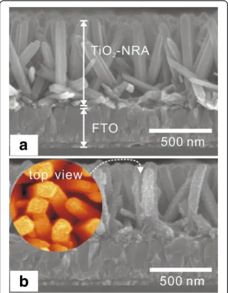
Figure 2a shows a typical side view of the SEM image of an as-synthesized TiO2-NRA. The rods stand almost
perpendicular to the substrate, have a similar diameter in the 40 to 50 nm range, and are about 500-nm long.
The TiO2 nanorods in the array are quite smooth
sur-faces. The SEM image of the TiO2-NRA after growth of
TiO2-QDs (TiO2-NRA@TiO2-QDs) is presented in
Fig. 2b. Compared to bare TiO2-NRA, obvious rough
grains eventually spanning the entire nanorod can be ob-served in the side view and top view. The XRD pattern of the NRA@QD sample (Additional file 1: Figure S1) was only indexed to TiO2, which confirms that the
rough grains are TiO2. Figure 3 shows a typical TEM
image of a sample of TiO2-NRA and TiO2-NRA@TiO2
-QDs. The TiO2nanorod was single crystalline with quite
a smooth surface (Fig. 3a). The lattice fringes with inter-planar spacings of 0.29 and 0.32 nm match the crystal planes (001) and (110) of rutile TiO2, respectively
(Fig. 3b) [16]. Figure 3c shows a typical TEM image of a single rod from the TiO2-NRA@TiO2-QDs. The coarse
surface clearly shows that the TiO2nanorod is covered
by a TiO2-QD layer. Figure 3d is a HRTEM image of the
rectangular area in Fig. 3c. The shell contains differ-ently oriented TiO2-QDs with 3−5 nm grain sizes. The
TiO2-NRA@TiO2-QD structures after bonding with
(Bu4N)2(Ru)(dcbpyH)2(NCS)2 (called N719) organic
molecules were characterized by the absorption spectra and the FT-IR (Additional file 1: Figure S2, in the Supplementary data), which suggest that N719 mole-cules are chemically grafted onto the TiO2surface.
HSCs based on TiO2-NRA, TiO2-NRA@TiO2-QDs,
and TiO2-NRA@TiO2-QDs@N719 with the conjugated
polymer MEH-PPV were fabricated, the architecture of the device is shown in Fig. 1. The illuminatedJ−Vcurves (Fig. 4) were measured under the AM 1.5 illumination of 100 mW/cm2 and the photovoltaic parameters were extracted in the Table 1. The MEH-PPV/TiO2-NRA
de-vice exhibits a rather low Voc(0.314 V), Jsc (2.048 mA/
cm2), and efficiency (0.236%) [7–12]. In contrast, after the 4-h growth of the TiO2-QDs on TiO2-NRA to form
the NRA@QD structure, the Voc are significantly
im-proved, accompanying little improvement in Jsc. Further
increasing the growth time of TiO2-QDs will lead to a
very slight increase in Voc, but theJscdecreased because
the decreased amount of polymer infiltrated into nanorod interspaces [17, 18]. After modifying the TiO2
-NRA@-TiO2-QDs (4 h) with N719 by an 4-h solvothermal
reac-tion, a higherJscof 3.233 mA/cm2was obtained, which is
2–3-fold higher than that of the MEH-PPV/pristine TiO2
-NRA counterpart device; however, the Voc decreased
slightly. The power conversion efficiency was enhanced from 0.236 to 0.911%. We also took the N719 reaction time of 8 h to modify the TiO2-NRA@TiO2-QD sample.
It was found that the Vocwas further decreased, but the
Jsc(4.222 mA/cm2) was further improved over the sample
with the 4-h reaction time. The devices also showed the good stability (Additional file 1: Figure S3, in the Supplementary data). These results suggest that Voc and
Jsc in polymer/TiO2-NRA solar cells can be tuned by
engineering their heterojunction interface with the inte-gration of inorganic and organic materials. The mechan-ism in detail of above phenomenon will be discussed as follows.
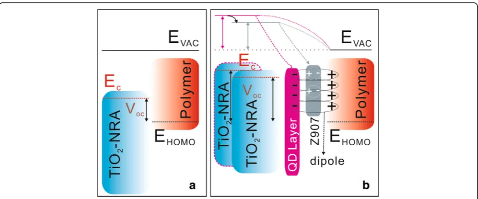
It is well known thatVocin the polymer/inorganic solar
cells is mainly determined by the energy levels of the Ec
edge in the inorganic material and highest occupied molecular orbital (EHOMO) band in the polymer (Fig. 5a)
[6, 19]. The larger Voc in the device with TiO2
-NRA@-TiO2-QDs than in the device with pristine TiO2-NRA has
been demonstrated from the generation of interfacial dipoles in QD shell/polymer interfaces [17, 18]. The inter-facial dipole generation can be considered as the forma-tion of weakly bound pairs of electrons and holes with separations of a few nanometers by Coulombic attraction
[20]. These interfacial dipoles commonly arise due to the trapping of electrons at surface states in TiO2-QD shell
with a negative charge at the metal oxide surface and posi-tive charge at the polymer (Fig. 5b) [19]. The Ec of the
TiO2nanorod can be changed byeδEwith the presence of
interfacial dipoles as is similar to the interfacial modi-fication with dipole molecules in P3HT/TiO2[21] and
P3HT/ZnO solar cells [22], in which δE is the change of the surface potential and can be calculated from Poisson’s equation [23],
δE¼Nμcosθ=εrε0 ð1Þ
where N is the dipole concentration, μ the dipole mo-ment,θthe angle the dipole makes to the TiO2nanorod
surface normal,εrthe dielectric constant of TiO2, andε0
the permittivity of free space. If dipoles are directed away from the TiO2 nanorod, cosθ> 0 and leading to
δE> 0; if dipoles are directed toward the TiO2nanorod,
cosθ< 0, leading to δE< 0. Therefore, the magnitude of Ec shifting correlates with the dipole concentration and
direction in the shell/polymer interface. With the Fig. 3TEM (a,c) and HRTEM (b,d) images of TiO2-NRA (a,b) and TiO2-NRA@TiO2-QDs. The images of TiO2-NRA@TiO2-QDs (c,d) were processed with pseudocolor to distinguish them from TiO2-NRA (a,b). The HRTEM image (d) was taken from the white frame on the corresponding TEM images (c)
[image:4.595.60.538.87.285.2]Fig. 4J−Vcurves of HSCs under the AM 1.5 illumination of 100 mWcm−2
Table 1Photovoltaic parameters of solar cells under the AM 1.5
illumination of 100 mWcm−2
Voc(V) Jsc(mA/cm2) FF (%) η(%)
[image:4.595.56.291.554.703.2] [image:4.595.304.540.648.731.2]presence of dipoles directed away from the TiO2 in the
shell/polymer interface (i.e., cosθ> 0) due to the TiO2
-QD shell (Fig. 8b), theEcof the TiO2nanorod core will
be shifted toward the local vacuum level of the polymer due to theδE> 0 (Fig. 5b).
The obtained Voc of 0.54 and 0.63 V for the
MEH-PPV/TiO2-NRA@TiO2-QDs&N719-based device,
how-ever, are somewhat lower than the value of 0.69 V for the MEH-PPV/TiO2-NRA@TiO2-QD-based counterpart
device. This results from the modification of the ZnO surface by N719, stemming from the dissociative adsorp-tion of the carboxylic acid group to form a carboxylate bond, in which the positive proton charge on the surface and the negative charge on the carboxylic group to-gether form an interfacial dipole [21, 22]. A theoretical calculation has demonstrated the direction of the dipoles generated by the adsorbed N719 molecules on the oxide surface with the monodentate anchoring mode directed to the oxide surface (i.e., cosθ< 0) (Fig. 5b) [22]. In this case, the dipole concentration generated by the modifi-cation with N719 will change theEcof the TiO2nanorod
withδE< 0 based on eq. (1). That means theVocwill be
reduced by shifting the band edge potential of TiO2
closer to the polymerEvac[20, 24]. TheVocin the
MEH-PPV/TiO2-NRA@TiO2-QDs&N719 device with 8 h of
N719 bonding time was further confirmed in this con-clusion (Fig. 2 and Table 1). The dipole concentration in the sample MEH-PPV/TiO2-NRA@TiO2-QDs&N719
with 4 h of N719 bonding time should be lower than the counterpart with 8 h. The magnitude of suppressed band edge shifting of TiO2(i.e.,δE< 0) should be smaller than
the 8-h sample based on eq. (1), which causes the Vocin
the 8-h device MEH-PPV/TiO2-NRA@TiO2-QDs&N719
to be lower than MEH-PPV/TiO2-NRA@TiO2-QD&N719
with 4 h. Therefore, there is a balance of dipole effects (i.e., positive or negative ofδE and its magnitude) by QD layer and N719 modification on deviceVoc.
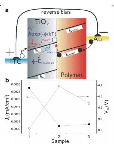
In addition, the interfacial dipoles were confirmed by the changed built-in voltage Vbi (Fig. 6) and reverse
current Js (Fig. 7). The Vbi related to built-in electric
field (Ebi) which originates the work-function difference
between the ITO and Au electrodes could be observed at the point where the dark J−Vcurve begins to follow quadratic behavior [25]. The interfacial dipoles (directed toward the polymer) could induce an extra polar electric field to enhanceEbi, which is confirmed by the enhanced
Vbi in Fig. 6a [22, 23]. Moreover, the Ec edge shifts in
the TiO2 nanorod due to the number of dipole
forma-tions also agree with the changes of the reverse satur-ation current density Js in the devices, which aroused
our much interest. It has been demonstrated that there is often an interface activation energy barrier ΦBat the
heterojunction, which is usually explained as a result of the energy level bending by the vacuum level misalign-ments at the heterojunction, and could be affected by formation of interface charge transfer state or dipoles [26, 27]; theΦBcan be evaluated from the dark reverse
saturation current in darkJ−Vcharacteristic by [40.41]
Js¼Aexp −nkTΦB
ð2Þ
where A is a coefficient with a value in the vicinity of 1000 A/cm2for the reverse bias current generation, and k and T are the Boltzmann constant and temperature, respectively.
[image:5.595.58.539.86.286.2]The current density−voltage of solar cells in the dark can be described by the following modified ideal diode equation [28]:
Jd ¼Js exp
q Vð −JdRsÞ
nkT
−1
ð3Þ
whereJsis reverse saturation current density, q
elemen-tary charge,Vapplied voltage,Rsdevice series resistance,
n diode ideality factor, k Boltzmann’s constant, and T temperature. We note that V> >JdRs for our devices,
sinceJdgenerally less than 0.01 A/cm2, and Rsis
gener-ally less than 200Ω/cm2. Neglecting theJdRsterm in eq.
(1), forV≥nkT/q, we can get the following relation:
lnJd≈lnJsþnkTq V ð4Þ
Equation (4) indicates that a plot of lnJd versus V
should yield a straight line. Therefore, Js and n can be
extracted from the lnJd−V curves in the linear region, which q/nkTand lnJs corresponds to the slope and
y-intercept, respectively (Fig. 8). Therefore, we extracted the approximate value of dark reverse saturation current Jsfrom the darkJ−Vcurve based on eq. 4 [29].
Based on eq. 2, we calculated the interface energy barrier ΦBvalues of all devices (Fig.7b). The energy barrierφfor
this process is correlated, but not necessarily just equal, to the difference between the Ec and EHOMO (Ec−EHomo in
Fig. 7a) due to the complicated interfacial dynamic pro-cesses [28, 30]. If there was a shift of the Ecedge in the
TiO2nanorod, it would affect the Ec−EHomo(i.e., φ), and
thereby influence theJs, based on eq. 2. The changes of
[image:6.595.60.538.87.264.2]de-viceJsandVocwith interfacial engineering are depicted in
Fig. 7b. It is observed that Js decreased from 2.76 × 10 −3mA/cm2
in the MEH-PPV/TiO2-NRA device to 2.03 ×
Fig. 6aSemilogarithmic plots of darkJD−Vcharacteristics of devices based on TiO2-NRA (1), TiO2-NRA@TiO2-QDs (2), and TiO2-NRA@TiO2-QDs@N719 (3). Thered dash linesindicateVbivalues.bDependence ofVoconVbiin devices
[image:6.595.57.291.357.653.2]10−4 mA/cm2 in the MEH-PPV/TiO2-NRA@TiO2-QD
device; therefore, the energy barrier φ(or Ec−EHomo)
in-creased based on eq. 2, which agrees with the expectation on the up-shift of theEcedge in the TiO2nanorod after
the growth of the QD layer in Fig. 5b. Additionally, the lit-tle increase ofJs(3.35 × 10⁻⁴mA/cm2) after the
engineer-ing of N719 agrees with the small downshift of theEcedge
in the TiO2 nanorod (i.e., φ) due to the adsorbed N719
molecules on the TiO2-QD surface with monodentate
anchoring mode directed to the TiO2surface in Fig. 5b.
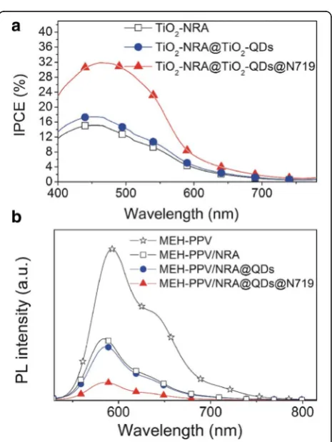
The improved Jsc in device performance after the
interface modification was studied by IPCE and PL spectra (Fig. 9). The slightly enhanced IPCE (or Jsc) in
the MEH-PPV/TiO2-NRA@TiO2-QD device resulted
from the small increase of the interfacial area due to the formation of the coarse shell for exciton dissoci-ation in comparison to the smooth surface of the original TiO2nanorods. However, the largely improved
Jsc by modification of the TiO2-NRA@TiO2-QDs with
N719 originates from the enhanced charge separation efficiency [22]. The amphiphilic dye improved the inter-face contact between the polymer and TiO2
-NRA@-TiO2-QDs, which improves the electronic coupling
property for charge transfer. These explanations agree with the PL quenching results (Fig. 9b). Obviously, the
PL intensity of the MEH-PPV/TiO2-NRA composite
decreases significantly as compared with the intensity of pristine MEH-PPV, indicating that the PL emission
of MEH-PPV can be quenched by TiO2 nanorods
resulting from the electron transfer from MEH-PPV to TiO2 [31]. After engineering the TiO2-NRA surface
with TiO2-QDs and TiO2-QDs@N719, the degree of PL
quenching become more obviously, especially in the
MEH-PPV/TiO2-NRA@TiO2-QDs@N719 sample. The
Fig. 8lnJd−Vcurves of solar cells measured in the dark (TiO2-NRA- (1), TiO2-NRA@TiO2-QD- (2), and TiO2-NRA@TiO2-QDs@N719-based (3))
[image:7.595.59.539.86.289.2] [image:7.595.306.539.374.684.2]PL quenching and IPCE (or Jsc) follow similar trends
indicating that the increased photocurrent upon the
MEH-PPV/TiO2-NRA@TiO2-QDs@N719 indeed
origi-nates from the better charge separation and transfer at the heterojunction interface.
Conclusions
The heterojunction interfacial engineering in polymer/ TiO2 nanorod array (NRA) hybrid solar cells was
per-formed in two steps: first, we grew TiO2-quantum dots
(QDs) on a TiO2-NRA surface to form the TiO2
-NRA@-TiO2-QD structure. Next, the TiO2-NRA@TiO2-QD
structure was further bonded with organic molecules (N719) on its surfaces to form the TiO2-NRA@TiO2
-QDs@N719 composite array through the solvothermal method. By controlling the interfacial engineering for polymer/TiO2-NRA solar cells through the integration
of TiO2-QDs and N719 molecules, the Voc and Jsc in
polymer/TiO2-NRA@TiO2-QDs@N719 solar cells can
be tuned, improving the device efficiency nearly four times compared with that of pristine TiO2-NRA-based
solar cells. The tunable device performance is resulted from the balanced interfacial dipoles, which is confirmed by the changed built-in voltage Vbi and reverse current
Js. These results therefore provide information crucial to
the optimization of interface in HSCs.
Additional file
Additional file 1:Supplementary Data. Figure S1. XRD of TiO2-NRA and TiO2-NRA@TiO2-QDs on the FTO substrate. Figure S2. (a) UV-vis absorption spectra of TiO2-NRA (□), TiO2-NRA@TiO2-QDs (○), and TiO2-NRA@TiO2 -QDs@N719 (△). The inset in (a) is the absorption spectra of N719 in the ethanol solution; (b) FT-IR spectra of TiO2-NRA@TiO2-QDs (1), TiO2 -NRA@-TiO2-QDs@N719 (2), N719 (3). Figure S3. TheJ−Vperformance of fresh device and measured after 60 days. (DOC 4431 kb)
Acknowledgements
We acknowledge the“1112 Talents Project”of Huzhou City and the valuable suggestions from the peer reviewers.
Funding
The role of the National Natural Science Foundation of China (21607041; 11547312; 11647306) is designing the work; the role of the Zhejiang Provincial Natural Science Foundation of China (LQ14F040003) is purchasing the materials; and the role of the Science and Technology Planning Project of Zhejiang Province (2017C33240), Seed Fund of Young Scientific Research Talents of Huzhou University (RK21056), and Foundation of Science and Technology Innovation Activities & Emerging Talents Plan of Zhejiang Province (2015R427005; 2016R42707) is the collection, analysis, and interpretation of the data.
Authors’Contributions
FW carried out the experiments and drafted the manuscript. YZ, XY, and JX participated in the device preparation. XL participated in the design of the study. YT conceived of the study and helped to draft the manuscript. All authors read and approved the final manuscript.
Competing Interests
The authors declare that they have no competing interests.
Author details
1School of Science and Key Lab of Optoelectronic Materials and Devices,
Huzhou University, Huzhou 313000, People’s Republic of China.2Department
of Material Chemistry, Huzhou University, Huzhou 313000, People’s Republic of China.
Received: 12 October 2016 Accepted: 28 January 2017
References
1. Zheng L, Han S, Liu H, Yu P, Fang X (2016) Hierarchical MoS2
nanosheet@TiO2nanotube array composites with enhanced photocatalytic and photocurrent performances. Small 12:1527–1536
2. Iandolo B, Wickman B, Svensson E, Paulsson D, Hellman A (2016) Tailoring charge recombination in photoelectrodes using oxide nanostructures. Nano Lett 16:2381–2386
3. Chiang C, Lee Y, Lee Y, Lin G, Yang M, Wang L, Hsieh C, Dai C (2016) One-step in situ hydrothermal fabrication of D/A poly(3-hexylthiophene)/TiO2 hybridnanowires and its application in photovoltaic devices. J Mater Chem A 4:908–919
4. Armstrong CL, Price MB, Munoz-Rojas D, Davis NJKL, Abdi-Jalebi M, Friend RH, Greenham NC, MacManus-Driscoll JL, Böhm ML, Musselman KP (2015) Influence of an inorganic inter layer on exciton separation
in hybrid solar cells. ACS Nano 9:11863–11871
5. Yu M, Long Y, Sun B, Fan Z (2012) Recent advances in solar cells based on one-dimensional nanostructure arrays. Nanoscale 4:2783–2796
6. Xu T, Qiao Q (2011) Conjugated polymer-inorganic semiconductor hybrid solar cells. Energy Environ Sci 4:2700
7. Xie YL (2013) Enhanced photovoltaic performance of hybrid solar cell using highly oriented CdS/CdSe-modified TiO2nanorods. Electrochim Acta 105: 137–141
8. Zhang Q, Yodyingyong S, Xi J, Myers D, Cao G (2012) Oxide nanowires for solar cell applications. Nanoscale 4:1436–1445
9. Liao W, Hsu S, Lin W, Wu J (2012) Hierarchical TiO2nanostructured array/ P3HT hybrid solar cells with interfacial modification. J Phys Chem C 116: 15938–15945
10. Baeten L, Conings B, D’Haen J, Hardy A, Manca JV, Van Bael MK (2012) Fully water-processable metal oxide nanorods/polymer hybrid solar cells. Sol Energy Mater Sol Cells 107:230–235
11. Hsu S, Liao W, Lin W, Wu J (2012) Modulation of photocarrier dynamics in indoline dye-modified TiO2nanorod array/P3HT hybrid solar cell with 4-tert-butylpyridine. J Phys Chem C 116:25721–25726
12. Liao W, Wu J (2013) Efficient electron collection in hybrid polymer solar cells: in-situ-generated ZnO/poly(3-hexylthiophene) scaffolded by a TiO2 nanorod array. J Phys Chem Lett 4:1983–1988
13. Lu H, Joy J, Gaspar RL, Bradforth SE, Brutchey L (2016) lodide-passivated colloidal PbS nanocrystals leading to highly efficient polymer: nanocrystal hybrid solar cells. Chem Mater 28:1897–1906
14. Wang J, Zhang T, Wang D, Pan R, Wang Q, Xia H (2012) Influence of CdSe quantum dot interlayer on the performance of polymer/TiO2nanorod arrays hybrid solar cell. Chem Phys Lett 541:105–109
15. Xia H, Zhang T, Wang D, Wang J, Liang K (2013) Composite interfacial modification in TiO2 nanorod array/poly (3-hexylthiophene) hybrid photovoltaic devices. J Alloys Compd 575:218–222
16. Liu B, Aydil ES (2009) Growth of oriented single-crystalline rutile TiO2 nanorods on transparent conducting substrates for dye-sensitized solar cells. J Am Chem Soc 131:3985
17. Wu F, Chen C, Zhao Y, Zhang H, Li X, Lu W, Zhang T (2014) Changes ofVoc in hybrid solar cells by TiO2nanoarray with different crystallinity of shell. J Electrochem Soc 161:H593–H597
18. Wu F, Cui Q, Qiu Z, Liu C, Zhang H, Shen W, Wang M (2013) Improved open-circuit voltage in polymer/oxide-nanoarray hybrid solar cells by formation of homogeneous metal oxide core/shell structures. ACS Appl Mater Interfaces 5:3246–3254
19. Ramsdale CM, Barker JA, Arias AC, MacKenzie JD, Friend RH, Greenham NC (2002) The origin of the open-circuit voltage in polyfluorene-based photovoltaic devices. J Appl Phys 92:4266–4270
21. Goh C, Scully SR, McGehee MD (2007) Effects of molecular interface modification in hybrid organic-inorganic photovoltaic cells. J Appl Phys 101:114503
22. Ruankham P, Macaraig L, Sagawa T, Nakazumi H, Yoshikawa S (2011) Surface modification of ZnO nanorods with small organic molecular dyes for polymer-inorganic hybrid solar cells. J Phys Chem C 115:23809–23816 23. Krüger J, Bach U, Grätzel M (2000) Modification of TiO2heterojunctions with
benzoic acid derivatives in hybrid molecular solid-state devices. Adv Mater 12:447–451
24. Samadpour M, Irajizad A, Taghavinia N, Molaei M (2011) A new structure to increase the photostability of CdTe quantum dot sensitized solar cells. J Phys D Appl Phys 44:045103
25. Mihailetchi VD, Blom PWM, Hummelen JC, Rispens MT (2003) Cathode dependence of the open-circuit voltage of polymer: fullerene bulk heterojunction solar cells. J Appl Phys 94:6849
26. Kippelen B, Brédas JL (2009) Organic photovoltaics. Energy Environ Sci 2:251 27. Potscavage WJ, Yoo S, Kippelen B (2008) Origin of the open-circuit voltage
in multilayer heterojunction organic solar cells. Appl Phys Lett 93:193308 28. Stevens DM, Speros JC, Hillmyer MA, Frisbie CD (2011) Relationship between
diode saturation current and open circuit voltage in poly(3-alkylthiophene) solar cells as a function of device architecture, processing conditions, and alkyl side chain length. J Phys Chem C 115:20806
29. Lee YJ, Davis RJ, Lloyd MT, Provencio PP, Prasankumar RP, Hsu JWP (2010) Open-circuit voltage improvement in hybrid ZnO–polymer photovoltaic devices with oxide engineering. IEEE J Sel Top Quantum Electron 16:1587–1594 30. Siddiki MK, Venkatesan S, Galipeau D, Qiao Q (2013) Kelvin probe force
microscopic imaging of the energy barrier and energetically favorable offset of interfaces in double-junction organic solar cells. ACS Appl Mater Interfaces 5:1279–1286
31. Ton-That C, Stockton G, Phillips MR, Nguyen TP, Huang CH, Cojocaru A (2008) Luminescence properties of poly-(phenylene vinylene) derivatives. Polym Int 57:496–501
Submit your manuscript to a
journal and benefi t from:
7Convenient online submission 7Rigorous peer review
7Immediate publication on acceptance 7Open access: articles freely available online 7High visibility within the fi eld
7Retaining the copyright to your article