Copyright © 2011 IJECCE, All right reserved 52 International Journal of Electronics Communication and Computer Engineering
Volume 2, Issue 1, ISSN (Online): 2249–071X, ISSN (Print): 2278–4209
A New Steganography Technique Based on
Amendment in Blue Factor
First A. Shweta Singhal, Second B. Dr. Sachin Kumar, and Third C. Manish Gupta
Abstract— In this paper, a new image steganography scheme
more suitable for which applications.
Image steganographic techniques can be divided into two is proposed which is a kind of spatial domain technique. In the
past few years a large number of algorithms for image steganography have been developed. A broad range of embedding algorithms goes from simple Least Significant Bit (LSB) methods to various spread spectrum schemes. J.G. Yu, E.J. Yoon, S.H. Shin and K.Y. Yoo [2008] have proposed a image steganographic technique based on 2k correction and edge detection. In this technique, 1 byte of blue factor of pixels of an image have been replaced with secret bits of text data. Image quality parameters of proposed technique are compared to the other best known image steganographic techniques. Comparison in the present study has been done on the basis of Peak Signal to Noise Ratio and Mean Square Error.
Index Terms— image, mean square error, Peak signal to
noise ratio, steganography.
I. INTRODUCTION
Information security means protecting information and information systems from unauthorized access, use, disclosure, disruption, modification or destruction. The terms information security, computer security and information assurance are being used frequently interchangeably. However, there are some subtle differences between them. These differences lie primarily in the approach to the subject, the methodologies used and the areas of concentration.
Basic Principles of Information Security:- v Confidentiality
v Availability v Integrity
Steganography is the art of hiding the fact that communication is taking place, by hiding information in other information. Many different carrier file formats can be used, but digital images are the most popular because of their frequency on the Internet. For hiding secret information in images, there exists a large variety of steganographic techniques some are more complex than others and all of them have respective strong and weak points. Different applications have different requirements of the steganography technique used. For example, some applications may require absolute invisibility of the secret information, while others require a larger secret message to be hidden. This paper intends to give an overview of image steganography, its uses and techniques. It also attempts to identify the requirements of a good steganographic algorithm and briefly reflects on which steganographic techniques are
groups [1]: the Spatial Domain technique group, and the Transform Domain technique group. The Spatial domain technique embeds information in the intensity of the pixels directly, while the Transform domain technique embeds information in frequency domain of previously transformed image. Our proposed scheme is a kind of the spatial domain techniques.
Image data embedding has been a popular research issue in recent years. It concerns mainly about embedding some proprietary data into digital media for the purpose of identification, annotation, and message transmission. Applications can often be found in two fields: one is the digital watermarking which provides protection of intellectual property rights and the other is the hiding of secret data within a host or cover signal. Both are constrained with a minimum amount of perceivable degradation to the host signal, which can be an image, audio, or video.
II. RELATED WORKS
The most of today‟s steganographic systems use images as cover object because people often transmit digital images over email and other communication media.
Several methods exist to utilize the concept of Steganography as well as plenty algorithms have been proposed in this regard. To gather knowledge in this particular research field, we have concentrated on some techniques and methods which are described below.
Least significant bit (LSB) insertion is a common and simple approach to embed information in a cover object. For images as a covering media, the LSB of a pixel is replaced with an M‟s bit. If we choose a 24-bit image as cover, we can store 3 bits in each pixel by modifying the LSBs of R, G and B array. To the human eye, the resulting stego image will look identical to the cover image [2, 3].
Wu and Tsai proposed a novel steganography technique using the pixel-value differencing (PVD) method to distinguish edge and smooth areas.
Pan et al. [4] proposed a data hiding technique for palette images with a few color existences as in cartoon images that are often synthetic graphics without complicated color and texture variations making invisible data embedding difficult. The scheme embeds the message in those pixels close to the boundaries. Although, experimental results showed a good visual quality it has a very low hiding capacity.
International Journal of Electronics Communication and Computer Engineering Volume 2, Issue 1, ISSN (Online): 2249–071X, ISSN (Print): 2278–4209
in the color palette. Liu defined specific modes of operation that limited the hiding capacity. The main draw back of these algorithms is that the hidden
capacity is relatively low, about 10% of the host image size was reported.
Jae-Gil Yu, Eun-Joon Yoon[7] proposed a new image steganography based on 2k correction and edge-detection, and the proposed scheme is a type of spatial domain technique. In order to hide secret data in a cover-image, we used JND model [8]. To hide more secret data , they used a method of the CSF which relates to also the characteristics of HVS with JND technique together. The method is an edge-detection which only uses 3-bits from MSB of each pixel-value. In order to have better imperceptibility, we proposed a 2k correction.
III. PROPOSED IMAGE STEGANOGRAPHY SCHEME In the proposed scheme, the work concentrated on one byte of a pixel (one byte of blue factor of a three byte pixel in an image), resulting better image quality.
In a computer, images are represented as arrays of values. These values represent the intensities of the three colors R(ed), G(reen) and B(lue), where a value for each of the three colors describes a pixel. Figure 1 shows an image containing group of pixels. According to RGB model, a pixel contains three color components that are red, green and blue component.
Figure 1: Image containing Group of Pixel4 Citations In this technique, sender and receiver should know common stego key. This stego key is used by receiver to extract secret message from stego image sent by sender to him. Sender selects an image called cover image or original image in which he wants to hide the secret message. Image containing the secret data is called stego image. Now, in this method, the bits of blue factor of pixels have been replaced by key and secret message. Firstly key is converted into binary form and its binary form is filled in the blue factor of first pixels. After then, secret message is converted into binary form and its binary form is filled in blue factor of next pixels. Blue channel is selected because a research was conducted by Hecht [9], which reveals that the visual perception of intensely blue objects is less distinct than the perception of objects of red and green. Figure 2 shows 24 bit size pixel. In this pixel, Blue layer in a pixel haves been replaced with data embedded blue layer.
Figure 2: Replacement of Blue Layer with Data Embedded Blue Layer
Example of Amendment in the blue factor of RGB
One can hide a message in three pixels of an image (3 byte colors). Suppose the original 3 pixels are:
(00100111 11101001 1100110) (00100111 11001000 11101001)
(11001000 00100111 11110001)
A steganographic program could hide the letter "A" which has a position 65 into ASCII character set and have a binary representation "01000001", by altering the blue channel bits of pixels and key be the letter “C” which has a position 67 into ASCII character set and have a binary representation "01000011".
(01000011 11101001 11001000) (01000001 11001000 11101000)
(11001000 00100111 11101001)
A. MECHANISM
1. Embedding phase
The embedding process is as follows.
Inputs: Image file , the text file and stego key Output: Text embedded image
Step 1: Original Image and Text File
The original image is of any file format having 24 bits per pixel. Due to low computational complexity, it can be applied to very small images (24 x 24) as well as large images (512 X 512). This technique can encode gray scale images as well as colored images directly, with R-G-B levels. After selecting image file, text file is selected which contains secret data.
Step 2: Stego Key
Copyright © 2011 IJECCE, All right reserved 54 International Journal of Electronics Communication and Computer Engineering
Volume 2, Issue 1, ISSN (Online): 2249–071X, ISSN (Print): 2278–4209
Step 3: Embedment of Data and Stego Key in Image using Amendment in the blue factor of RGB
Figure 3: Proposed Encoding Technique
Encoding algorithm of amendment in the blue factor of RGB includes following steps:
Step (a): Extract all the pixels in the given image and store it in the array called Pixel-Array.
Step (b): Extract all the characters in the given text file and store it in the array called Character- Array.
Step (c): Extract all the characters from the Stego key and store it in the array called Key- Array.
Step (d): Choose first pixel and pick characters from Key- Array and place it in first component of pixel. If there are more characters in Key- Array, then place rest in the blue factor of next pixels, otherwise follow Step (e).
Step (e): Place some terminating symbol to indicate end of the key. „0‟ has been used as a terminating symbol in this algorithm.
Step (f): Place characters of Character- Array in each blue factor of next pixels by replacing it.
Step (g): Repeat step (f) till all the characters has been embedded.
Step (h): Again place some terminating symbol to indicate end of data.
Step (i): Obtained image will hide all the characters that we input.
Data is embedded using above algorithm and stego image is produced and sent to the receiver or legitimate user.
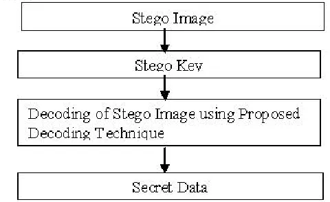
2. Extraction phase
The extraction process is as follows. Inputs: Embedded image file Output: Secret text message Step1: Stego Image
The sender sends a stego image to the receiver or legitimate user. The legitimate user is having the stego key to decode secret data from stego image.
Step 2: Stego Key
After receiving stego image by receiver or legitimate user, the legitimate user must have the same key with which the
image is encoded.
Step 3: Decoding of Stego Image using Proposed Decoding Technique.
At last the stego key will decode the image, and the secret data is recovered.
Decoding algorithm of amendment in the blue factor of RGB includes following steps:
Step (a): Consider three arrays. Let they be Character-Array, Key-Array and Pixel-Array.
Step (b): Extract all the pixels in the given image and store it in the array called Pixel-Array.
Step (c): Now, start scanning pixels from first pixel and extract key characters from blue factor of the pixels and place it in Key-Array. Follow Step 3 till we get terminating symbol, otherwise follow step (d).
Step (d): If this extracted key matches with the key entered by the receiver, then follow Step 5, otherwise terminate the program by displaying message “Key is not matching”.
Step (e): If the key is valid, then again start scanning next pixels and extract secret message characters from blue factor of next pixels and place it in Character Array. Follow Step (e) till we get terminating symbol, otherwise follow step 6.
Step (f): Extract secret message from Character-Array. Thus in this way secret message is decoded and received by receiver.
Figure 4 : Proposed Decoding Technique
IV. RESULTS
A. PSNR and MSE for Colored as well as Gray-scale Images
International Journal of Electronics Communication and Computer Engineering Volume 2, Issue 1, ISSN (Online): 2249–071X, ISSN (Print): 2278–4209
in decibels, between two images. This ratio is often used as a quality measurement between the original and a compressed image. The higher the PSNR, the better the quality of the compressed or reconstructed image. The MSE (Mean Square Error) represents the cumulative squared error between the compressed and the original image, the lower the value of MSE, the lower the error. Each picture element (pixel) has a color value that can change when an image is compressed and then uncompressed. Signals can have a wide dynamic range, so PSNR is usually expressed in decibels, which is a logarithmic scale.
To compute the PSNR, the following steps are:
1) Define the bel and decibel. The bel is defined mathematically as LB = log10 (P1/P0) where P1 and P0 are two quanties that are in the same units of measure. The decibel is 0.1 bel, so the decibel value LdB is LdB = 10 log10 (P1/P0).
2) Define the mean squared error (MSE) between two monochromatic images, where one image is considered to be an approximation of the other. The MSE can be described as the mean of the square of the differences in the pixel values between the corresponding pixels of the two images.
3) Express MSE mathematically from the description in Step 1. We therefore have MSE = 1/mn [ΣΣ (I(i,j) - K(i,j))^2] where I and K are matrices that represent the images being compared. The two summations are performed for the dimensions "i" and "j." Therefore I(i,j) represents the value of pixel (i,j) of image I.
4) Determine the maximum possible value of the pixels in image I. Typically, this may be given as (2^n) - 1 where n is the number of bits that represent the pixel. Thus, an 8-bit pixel would have a maximum value of (2^8) - 1 = 255. Let the maximum value for pixels in image I be MAX.
5) Express the PSNR in decibels. From Step 1, we have the decibel value LdB as LdB = 10 log10 (P1/P0).
Now let
P1 = MAX^2 and P0 = MSE. We then have
PSNR = 10 log10(MAX^2/MSE) =10log10(MAX/(MSE)^(1/2))^2 = 20 log10(MAX/(MSE)^(1/2)). Therefore,
PSNR=20log10(MAX/(MSE)^(1/2)).
The results are obtained in tabular form for above images using PSNR calculator tool. The values of PSNR and MSE and the comparison between PSNR and MSE are shown in Table 1
(Figure 5(a)) (Figure 5(b))
(Figure 6(a)) (Figure 6(b))
Figure 5 (a): Original JPEG Image Lena(C), Figure 5 (b): Stego JPEG Image Lena (C), Figure 6 (a): Original JPEG Image Lena (G), Figure 6 (b): Stego JPEG Image Lena (G)
B. COMPARISON WITH EXISTING TECHNIQUES
Best known algorithm giving higher PNSR values is
J.G. Yu’s image steganographic technique based on 2k
correction and edge correction. This technique gives better results than LSB3, PVD method and Lie-Chang’s method.
Copyright © 2011 IJECCE, All right reserved 56 International Journal of Electronics Communication and Computer Engineering
Volume 2, Issue 1, ISSN (Online): 2249–071X, ISSN (Print): 2278–4209
V. CONCLUSION
The image quality metrics i.e. higher Peak Signal to Noise Ratio (PSNR) and lower Mean Square errors itself prove that the proposed technique for image steganography is good one as PSNR value is greater than 45 and MSE value is less than 1.
The comparison with the best known steganography technique by J.G. Yu‟s technique (PSNR < 45) proves that the newly proposed and implemented algorithm gives much better results than J.G. Yu‟s algorithm.
Higher values of PSNR for each single color patterns also prove the robustness of the proposed algorithm.
VI. REFERENCES
[1] H.T.S.M.KharraziandN.Memon. ImageSteganography: ConceptsandPractice. WSPC, 2004.
[2] Johnson, N. F. and Jajodia, S, “Exploring steganography: Seeing the unseen”, IEEE Computer Magazine, pp. 26-34, February 1998.
[3] S.K.Bandyopadhyay, Debnath Bhattacharyya, Poulumi Das, S. Mukherjee, D. Ganguly, “A Tutorial Review on Steganography”, IC3 Noida, pp. 106-114, August 2008. [4] Gang Pan, Zhaohui Wu and Yunhe Pan, “A Data Hiding
Method for Few-Color Images”, IEEE Proceedings of the 2002 International Conference on Acoustic, Speech, and Signal Processing, ICASSP '02, Vol. 4, 13-17 May 2002..
[5] Jessica Fridrich, Miroslav Goljan, and Rui Du “Losless data embedding for all image formats”, The International Society for Optical Engineering, SPIE 2003.
[6] Liu Hangmei, Zhang Zhefeng, Huang Jiwu, Huang Xialing and Yun Q. Shi, " A high capacity distortion-free data hiding algorithm for palette image", IEEE Proceedings of the 2003 International Symposium on Circuits and Systems, ISCAS '03, Vol. 2, 25-28 May 2003.
[7] Jae-Gil Yu, Eun-Joon Yoon “A New Image Steganography Based on 2k Correction and Edge-Detection. Fifth International Conference on Information Technology ,IEEE 2008
[8] W. N. Lie and L. C. Chang. Data hiding in images with adaptive number of least significant bits based on the human visual system. Proc.ICIP‟99, 1:286–290, 1999.
[9] E. Hecht, Optics, 2nd Ed, Addison Wesley, 1987. [10] H.V. Singh, S.P. Singh and A. Mohan, “A New Robust
Method of Hiding Text Characters for Secure Open Channel Transmission,” International Journal of Computer Science and Network Security, vol. 7 (7), pp. 31-36, July 2007.
[11] J. He, S. Tang and T. Wu, “An Adaptive Image Steganography Based on Depth-Varying Embedding,” In Congress on Image and Signal Processing, vol. 5, pp. 660-663, 27-30 May 2008.
[12] S.G.K.D.N. Samaratunge, “New Steganography Technique for Palette Based Images,” In Second International Conference on Industrial and Information Systems, pp. 335-340, Aug. 8 – 11, 2007.
[13] S.K. Moon and R.S. Kawitkar, “Data Security using Data Hiding,” International Conference on Computational Intelligence and Multimedia Applications, vol. 4, pp. 247-251, 2007.
[14] Y.R. Park, H.H. Kang, S.U. Shin and K.R. Kwon, 2005. “A Steganographic Scheme in Digital Images Using Information of Neighboring Pixels,” In International
Conference on Natural Computation, pp. 962-967,
2005.
First A. Shweta Singhal, B.Tech (CSE), Working as Senior lecturer in Department of Computer Science and Engg, Rajkumar Goel Institute of Technology, Ghaziabad (UP), India.
Second B. Dr. Sachin Kumar, M.tech (CS), Ph.D(CS), Working as Associate Professor in Department of Information Technology, Rajkumar Goel Institute of Technology, Ghaziabad (UP), India.