DFIG Based SWECS Operation in Microgrid
by Controlling Frequency and Regulating
Voltage
K.P. Nithya1, P.Priya2, T.S. Maheshwari3 , G. Jancy Rani4 , A.Jayasri5
Assistant Professor, Department of EEE, Panimalar Institute of Technology, Chennai, India1,2.
B.E Student, Department of EEE, Panimalar Institute of Technology, Chennai, India3,4,5.
ABSTRACT:This paper focuses on the impact of frequency, voltage regulation, along with active and reactive power capabilities in wind power plants operating parallely in micro-grids. A micro-grid control model for distributing the load variations in system and wind turbine model with capability to control output power is developed in simulink.The main aim of this control strategy is to maintain the frequency and voltages within safe limits and also to control the active and reactive power from wind power plants when operating in parallel with the grid. A comparison of system voltage and frequency is done to demonstrate the effectiveness of wind power plants in the regulation mode when compared with present wind power plants operating at maximum active power. This study helps to determine the amount of wind power that can be delivered into the system under new controlling mode without compromising onreliability and integrity of the system
KEYWORDS:Standalone Wind Energy Conversion System(SWECS), Doubly Fed Induction Generator (DFIG), Battery Energy Storage System (BESS), Power Quality.
I. INTRODUCTION
demand is high, then the battery is discharged. This feature is termed as power levelling. So by integrating BESS in this DFIG, assured power supply can be achieved irrespective of the wind speed.Mindset.al [18] have also used BESS in conjunction with WECS through a buck-boost DC-DC converter. Goelet.al [19] has connected BESS directly on the DC link of two back toback connected VSCs. But in that voltage and frequency controller, terminal voltage is regulated by controlling the Load Side Converter (LSC). So the stator is not working exactly at unity power factor. Therefore, the power generating capability may be reduced because of the reactive power.In direct current control method, the LSC currents which consist of harmonics and unbalance are considered as reference currents for the controller. However, in an indirect current control, the reference current is the stator current, which is balanced and sinusoidal. This indirect current control increases the tracking capability as compared to direct current control. By using an indirect current control of LSC, the stator currents are made to be balanced depending upon the MPPT condition. As the stator currents are controlled to be the balanced and sinusoidal, the unbalancing and harmonics in the load currents are supplied through LSC only. This is called as load compensation and harmonics elimination.
II.SYSTEMCONFIGURATION
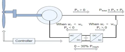
The doubly fed induction generator consists of a wind turbine connected to the rotor shaft of the induction generator through a gear train. The topology used in this scenario uses a converter capable of supplying and receiving power from the rotor to the grid. This converter consists of two separate devices with different functions connected to each other via a DC interconnection link i.e. a dc link capacitor. These two devices are separate converters, one connected to the grid and the other connected to the rotor. The converter connected to the generator controls the real and reactive power output of the wind turbine and the grid connected converter maintains the dc link capacitor voltage at the set point. A wind turbine connected to a double fed induction generator equipped with a grid side and a generator side converter is shown in Figure 1.
Figure 1 Double fed induction generator schematic
In this DFIG based SWECS, the loads are connected to stator windings of the DFIG. RSC is connected to rotor terminals and LSC is connected to the stator or the load with inductors. For supplying guaranteed power to the consumers, a BESS is connected in the DC link of back to back connected converters. In this system, a wound rotor induction machine is coupled to the DC machine. The wind turbine characteristics are emulated using DC machine and Type-A chopper.
2.1 Generator Side Converter Control
The variations in stator flux are negligible hence are assumed to be constant. Also it is assumed that there would not be any occurrence of saturation. Because of its small presence the stator resistance is considered as zero. To make the calculation simpler it is assumed that the stator flux is along the d axis in the d-q frame. Therefore,
=
= 0
= −
The power output from the stator can be written as:
= ∗
=3
2 ∗ + ∗ =
3
2( ∗ )
=3
2 ∗ − ∗ = −
3
2( ∗ )
From these equations it is evident that the active power delivered at the stator terminals can be controlled by the Iqr component and the reactive power can be controlled by the Idr component assuming constant stator flux. Therefore, to control the DFIG output, a control scheme may be applied to vary the Idr and Iqr values to achieve the required power output set point.
2.2 Grid Side Converter Control
The main purpose of the grid side converter is to maintain a constant dc link voltage. To maintain this dc link voltage, the converter takes power from the grid and generates a dc current which keeps the capacitor in the dc link charged. This charged capacitor maintains a constant voltage at the terminals of the generator side converter. The control signal for the grid side converter is the pre-determined voltage set point.
2.3 Capability of Doubly Fed Induction Generator
Active and reactive power capability information of a machine is essential in analyzing the stability of the machine. The capability of any machine depends on its physical construction and materials used. For a DFIG machine, the active power output is limited by the prime mover capability.Similarly, reactive power output is limited by the maximum current and heating limits of the armature and the field coil. These physical limitations guide the capability of the machine. The capability of a DFIG presents similarities to the conventional synchronous generator capability. The active power varies with the wind speed and the slip is assumed to be constant here.
III.MODELLING
3.1 Synchronous Generator Modelling
The synchronous generator model consists of three parts, the synchronous machine model, and the governor model with hydraulic turbine, and the excitation system. A governor model takes the frequency change as an input and changes the servomotor output to provide adequate mechanical power to offset the frequency change from the reference. This model produces available mechanical power as an output which is then fed to the synchronous machine. The excitation system produces the required field voltage for the synchronous machine to maintain the commanded generator terminal voltage. The synchronous machine model takes available mechanical power and required field voltage as an input from the governor and excitation system models, and produces the required current and line-to-line voltage.
3.2Wind Power Plant Modelling
power vs turbine speed curves). Beyond point D, the reference power is a constant equal to one per unit (1 pu).
Figure 2 Wind turbine power characteristics
3.3Wind Turbine Modelling
A Simulink model is developed as shown in figure below.
Figure 3 Simulink wind turbine model
3.4DFIG modelling
The Doubly Fed Induction Generator is modelled as an asynchronous machine with the commanded d-q axis voltage as one of the input with the a-b-c phase terminal voltage and the torque produced by the wind turbine as the other two inputs.
The model outputs all the a-b-c and d-q axis voltage and current quantities of stator and rotor as an output.
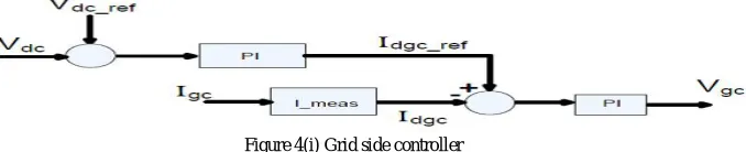
3.5 Grid Side Converter Modelling
The grid side converter is used to regulate the voltage of the DC bus capacitor. The control system for the grid side converter is displayed below in Figure 4(i). The d-axis (for d-q transformation) of the rotating reference frame is aligned with the positive sequence of the terminal voltage.
Figure 4(i) Grid side controller
Figure 5(ii) Logic for grid side converter
IV.CONTROLSTRATEGIESOFDFIGWITHBESS
RSC is controlled in stator flux oriented reference frame and LSC is controlled in voltage oriented reference frame.
4.1 Rotor Side Converter Control Algorithm
The main purpose of the RSC is to maintain the voltage and frequency constant and also for extracting maximum power. As the RSC is controlled in stator flux oriented reference frame, stator active and reactive powers (PS & QS) are controlled by quadrature and direct axis rotor currents (iqr&idr) respectively.The terminal voltage at the stator is controlled by controlling direct axis rotor current (idr).The direct axis rotor reference current (idr*) is obtained from the terminal voltage controller same as the above case. However, the active component of rotor current (iqr) is controlled for achieving maximum power point operation. The speed is controlled by controlling quadrature axis reference rotor current (iqr*). iqr* is obtained by processing the speed error (er) between reference and estimated rotor speeds (r* and r)through PI controller. Here, the tip speed ratio based MPPT control algorithm is used for selecting the reference speed. Measured wind speed from an anemometer is converted into reference rotor speed by using the pre-known value of the optimal tip speed ratio. Actual speed (r) is calculated from the encoder. Reference d-axis and q-axis components (idr*and iqr*) are converted into three phase rotor currents (irabc*) by using inverse park's transformation.These reference rotor currents (ira*, irb*, irc*) are compared with the sensed rotor currents (ira, irb, irc) and the current error is passed through the PI controller for estimating the modulating signals. These modulating signals are compared with the fixed frequency PWM for switching the RSC.
Figure 6 Rotor side controllers
4.2 Load Side Converter Control Algorithm
ids*=-(Lm/Ls)*iqr.
For achieving unity power factor operation at stator, iqs* ismade zero. Reference stator currents (isa*,isb* and isc*) are calculated from the direct and quadrature axis reference currents (ids*, iqs*).Sensed stator currents (isa, isband isc) are compared with the reference stator currents (isa*, isb* and isc*) and the current error is passed through the PI controller for estimating the modulating signals. These modulating signals are compared with the fixed frequency PWM for switch LSC.
V.NEEDFORFREQUENCYCONTROLINDFIG
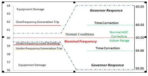
Frequency control in a power system is done to maintain a sufficient harmony balance between the consumed and generated active powers, so that the frequency remains within acceptable limits around the nominal frequency. With constantly changing power demand, frequency control becomes an important task for a power system.Generally, the changing system load is predictable and units are committed and dispatched based on the forecasted load levels. Therefore, under normal operating conditions, the balancing of energy is achieved by adjusting the generator active power set-points. Signals to generators for such adjustments are either issued by the system operator or automatically generated and issued by automatic generation control (AGC). In the event of a load change or any unexpected event like loss of generation, an imbalance of load occurs in the system which causes frequency excursions. Every power system tries to fight the frequency excursion by releasing the stored kinetic energy in the form of system inertia. In every system, with increase in the load, the kinetic energy is released and reduction of the load results in absorption of the kinetic energy which tries to maintain the nominal frequency of the system. This inherent system inertial response due to the masses of the connected generators and the load is not sufficient to return the system frequency to its nominal value. Hence frequency control is normal operation of the grid as suggested by CERTS is shown in Figure 7. In an islanded system, these frequency guidelines are a bit relaxed giving normal frequency operation of ± 1.2 Hz required to support the stable and secure operation of the power system.In large interconnected power systems, the power imbalances created due to the loss of single component are small when compared to the total system size. In addition, the inertia of the system also contributes towards restricting the rate of frequency change. Thus the frequency deviations are small in large systems.
Figure 7. Frequency relaxation limits
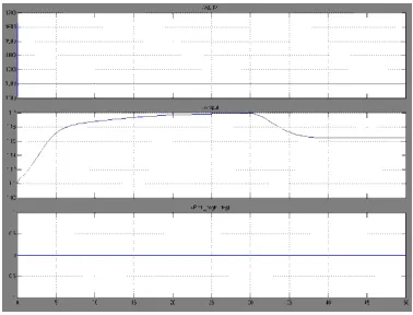
VI.SIMULATIONRESULTS
Figure 8. One line diagram for the test system
A micro grid model is developed in Simulink as shown in Figure 9 based on the one line diagram of Figure 8. This model is developed as a phasor model to expedite the simulation process. In phasor simulation, changes in magnitude and phases are calculated instead of solving complex differential equations. This type of simulation saves computational time that is required to solve the differential Equations.
Figure 9. Micro grid test system implemented in Simulink
Figure 10. Micro grid test subsystem implemented in SimulinkFigure 11.Wind turbine1
Figure 12.Conventional generator Figure 13. Wind turbine
VII. CONCLUSION
penetration of wind power in a micro-grid. These scenarios also included testing of the micro grid system with and without the proposed control strategy for comparison. Observations made from this study revealed the effectiveness of the control methodology to smooth out the frequency and voltage fluctuations appearing in the isolated system. A reliable generation mix configuration of conventional and wind power generation for the two cities was also deduced which was observed to be in respect to the overall wind capacity in that location throughout the year. This control methodology and the system can be easily modified and scaled to specific requirements and can be used to study integration effects of other renewable or non-conventional energy sources. The next step can be the development of a methodology for assessing and controlling a micro grid equipped with all kinds of non-conventional energy sources like rooftop or community solar photovoltaic plants, fuel cells, internal combustion engine generators, micro-turbines, battery energy storage systems, and plug-in hybrid electric vehicles. These non-conventional energy sources have the potential to support a micro grid in need of active and reactive power sources. Inclusion of these energy sources into the micro-grid would definitely help to strengthen its reliability. Lastly, this structure can be used as a building block for an interconnected pool of micro grids to study its effect on the reliability and flexibility of grid operations.
REFERENCES
[1]Vaughn Nelson, “Wind Energy Renewable Energy and the Environment”, CRC Press 2009. [2]Manfred Stiebler, “Wind Energy Systems for Electric Power Generation”, Springer 2008.
[3]Sathyajith Mathew and Geeta Susan Philip, “Advances in Wind Energy Conversion Technology, springer, 2011.
[4] Hermann-Josef Wagner and JyotirmayMathur, “Introduction to Wind Energy Systems Basics, Technology and Operation”, Springer 2009. [5] L. Holdsworth, X. G. Wu, J. B. Ekanayake and N. Jenkins, Comparison of fixed speed and doubly-fed induction wind turbines during power system disturbances,” Proc. Inst. Elect. Eng. Gen. Trans. Dist., vol. 150, no.3, pp. 343–352, May 2003.
[6] S. S. Murthy, B. Singh, P. K. Goel and S. K. Tiwari, “A Comparative Study of Fixed Speed and Variable Speed Wind Energy Conversion Systems Feeding the Grid”, in Proc. IEEE 7th Inter. Conf. Power Elect. & Drive Systems, 2007 PEDS '07, 27-30 Nov. 2007, pp. 736-743.
[7] R. Datta and V. T. Ranganathan, “variable-speed wind power generation using doubly fed wound rotor induction machine-a comparison with alternative schemes,” IEEE Trans. Energy Con.,vol.17,no.3,pp.414-421, Sep 2002.
[8] R. Pena, J. C. Clare and G.M Asher, “Doubly fed induction generator using back-to-back PWM converters and its application to variable speed wind-energy generation,” Proc. Inst. Elect. Eng., Elect. Power Appl., vol. 143, no. 3, pp. 231 – 241, May 1996
[9] S. Muller, M. Deicke and R. W. De Doncker, “Doubly fed induction generator systems for wind turbines,” IEEE Ind. Appl. Mag., vol. 8, no. 3, pp. 26-33, May/Jun 2002.
[10] R. Pena, J. C. Clare and G. M Asher, “A doubly fed induction generator using back-to-back PWM converters supplying an isolated load from a variable speed wind turbine,” Proc. Inst. Elect. Eng., Elect. Power Appl., vol. 143, no. 5, pp. 380 – 387, May 1996.
[11] A. K. Jain and V. T. Ranganathan, “Wound rotor induction generator with sensorless control and integrated active filter for feeding nonlinear loads in a stand-alone grid,” IEEE Trans. Ind. Elect., vol. 55, no.1, pp. 218-228, Jan. 2008.
[12] R. Cardenas, R. Pena, J. Proboste, G. Asher and J. Clare, “MRAS observer for sensorless control of standalone doubly fed induction generators,”
IEEE Trans. Ener.Con., vol. 20, no. 4, pp. 710-718, Dec.2005.
[13] B. Singh and S. Sharma, “Doubly fed induction generator-based off-grid wind energy conversion systems feeding dynamic loads,” Proc. Inst. Elect. Eng., Power Elect., vol. 6, no.9, pp.1917-1926, Nov. 2013.
[14] ChanglingLuo, H. Banakar, B. Shen and Boon - TeckOoi, “Strategies to Smooth Wind Power Fluctuations of Wind Turbine Generator,” IEEE Trans. on Energy Conv., vol.22, no.2, pp.341-349, June 2007.
[15] G. Mandic, A. Nasiri, E. Ghotbi and E. Muljadi, “Lithium-Ion Capacitor Energy Storage Integrated With Variable Speed Wind Turbines for Power Smoothing,” IEEE J. Emerg. Sel. Topics Power Electron.,vol. 1, no. 4, pp. 287-295, Dec. 2013.
[16] Daniel H. Doughty, Paul C. Butler, Abbas A. Akhil, Nancy H. Clark and John D. Boyes, “Batteries for Large-Scale Stationary Electrical Energy Storage” The Electrochemical Society Interface, Fall 2010.
[17] V. C. Ganti, B. Singh, S. K. Aggarwal and T. C. Kandpal, “DFIG-Based Wind Power Conversion With Grid Power Leveling for Reduced Gusts”, IEEE Trans. Sust.Ener., vol.3, no.1, pp.12-20, Jan. 2012.
[18] N. Mendis, K. M. Muttaqi, S. Sayeef and S. Perera, “Standalone Operation of Wind Turbine-Based Variable Speed Generators With Maximum Power Extraction Capability,” IEEE Trans. Energy Conver., vol.27, no.4, pp.822-834, Dec. 2012.
[19] P. K. Goel, B. Singh, S. S. Murthy and N. Kishore, “Modeling and control of autonomous Wind Energy Conversion System with Doubly Fed Induction Generator,” in Proc. Joint Inter. Conf. on Power Elect. Drives &Ener. Systems (PEDES) & 2010 Power India, 20-23 Dec. 2010.