2584
©IJRASET: All Rights are Reserved
Speed Control of Three Phase Induction Motor by
using V/f Method
Chanda Ghaguskar
1, Megha Londhe
2, Prajakta Bawankar
3, Nishant Badwaik
4, Pritesh Lanjewar
5, Sumit Thakre
6,
Santoshi Gawande
71, 2, 3, 4, 5, 6, 7Department of Electrical Engineering at K.D.K. College of Engineering, Nagpur 440009, India
Abstract: This project aim to control the speed of induction motor by VFD as well as protecting the induction motor and VFD. This project present the need of speed control in induction motor. Out of the various methods of controlling induction motor, V/f control has proven to most versatile. The overall project of speed control and protection of motor has been presented. It is very important to control speed of induction motor in industry and engineering application. Efficient control method are used for economic operation of project. The speed control techniques of induction motor can be broadly classified into two types- scalar control and vector control. Scalar control involves controlling the magnitude of voltage and frequency of induction motor also for protecting the VFD and induction motor. The objective is to get the variation in the speed of three phase induction motor by varying the supply frequency using variable frequency drive and to achieve the minimum and maximum value of speed at respective frequencies.
Keywords: Variable Frequency Drive, IGBT, Inverter, Pulse Width modulation.
I. INTRODUCTION
The induction motor is widely used in various industrial application . The loads on induction motor always vary as per its applications but speed of induction motor is constant and cannot match with load demand. If load on induction motor decreases the speed of induction motor can not be decreases as per the load. Hence it takes rated power from supply so the energy consumed by motor is same. As the energy consumption is same during variation of load conditions also is a critical situation for Induction motor. To overcome this problem the Variable Frequency Drive is used in industrial application to save the energy consumption and electricity billing. The use of Variable frequency drive has increased dramatically in a industrial application. The VFDs are now commonly used. This device uses power electronic switches to vary the frequency of input power. There by controlling motor speed. Variable frequency drive is divided into three major sections as described below and each section has play an important role. First section is rectifier and next is the DC bus. The lateral section is the inverter section with which load is connected. An illustration of all these sections is given below in figure 1.
230
AC
2585
©IJRASET: All Rights are Reserved
A. Rectifiers
This section can comprises of diodes, transistors or silicon controlled rectifiers. But usually diodes are used because of their lower cost. AC voltages coming from main line have positive and negative peaks. When these voltages are fed in to bridge type configuration of diodes of this rectifier section the negative peaks are vanished only positive peaks retain. In this way the frequency of the coming voltages doubles. It also called AC to DC converter. In order to remove ripples present in the waveform, the pulsating dc passing through the capacitor filter. The distortion cause by ripple is remove and give smooth DC voltage for working of electrical application.
B. DC Bus
The voltages coming from AC to DC converter is store in DC bus . This consist of capacitors and some other items like inductors or chokes in order to smooth the power supply coming from the previous section. DC bus is remove ripple from stored voltage. Thus this DC bus is play important role in removing ripples from voltage as well as it helps in improving power factor correction.
C. Inverters
The last stage of VFD is inverter. The inverter made up of IGBT. The IGBT works as a switch. In most of industry insulated gate bipolar transistor commonly used. If one of the switch from the top get closed then phase of electric motor get connected to positive DC bus and the voltage on that phase becomes positive. Same principal get used for the switches and bottom and foe. These bottom switch phase get negative DC bus and voltage on that phase become negative.
Pulse width modulation is the commonly used for controlling speed and frequency of motor. This can be done by using micro-controller. In this research we selected a range of 5Hz to 50Hz frequency using PWM. The basic principle of PWM is that a sine wave is generated in the microcontroller which is super imposed on a triangular wave. This results in a square wave which is then fed to inverter section. with the changing duty cycles of the pulse, width of square wave is controlled . Basically duty cycles describes the time for which pulse waveform turned on and off. Thus by switching the waveform between two discrete levels the square wave is approximated with a sine wave of desired duty cycles. These pulses are fed to the switches for turning ON and OFF as desired. By turning on switches in any order, the phase and the rotation of electric motor can be changed. So making of phase voltage positive, negative or zero, variable frequency get at output. As a frequency directly proportional to speed of motor and motor speed varied according to requirement or application. So inverter is a unit where filtered DC supply is being converted to AC supply which is fed to electric motor.
1) Speed Control Techniques: Speed control is achieved in the inverter driven induction motor by means of variable frequency. Apart from frequency, the applied voltage needs to be varied, to keep the air gap flux constant and not let it saturate. This is explained as follows. The air gap induced emf in an ac machine is given by
E
1
4
.
44
k
1
mf
s
1 ...(1)where
k
1
is the stator winding factor,
m is the peak air gap flux,f
s is the supply frequency, and
1is the number of turnsper phase in the stator. Neglecting the stator impedance,
R
s
jX
1s, the induced emf approximately equals the supply-phasevoltage. Hence.
V
ph
E
1 ...(2)The flux is then written as
m
f
K
V
s b
ph
...(3)
where
K
b
4
.
44
k
1
1 ...(4)If
K
2586
©IJRASET: All Rights are Reserved
m
f
K
V
Vf s
ph
...(5)where
K
Vf is the ratio between
V
ph andf
s.From equation (5), it is seen that , to maintain the flux constant.
K
Vf has to be maintained constant. Therefore Whenever stator
frequency is changed to obtain speed control, the stator input voltages have to be changed accordingly to maintain the air gap flux constant.
2) Types of Speed Control of Induction Motor: A number of control strategies have been formulated, depending on how the voltage to frequency ratio is implemented:
a) Constant volts/Hz control
b) Constant slip-speed control
c) Constant air gap flux control
d) Vector control
Constant Volts / Hz Control Method
With the help of supply frequency the synchronous speed can be controlled.
P
f
N
s120
………(6)The stator voltage is
fE
1 …………(7)where
is the air-gap flux and f is the supply frequency when the voltage gets induced. As the stator voltage drop neglected theterminal voltage will
fV
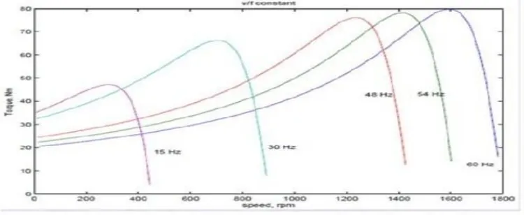
1 ………..(8) [image:3.595.110.485.573.727.2]The air gap increases when the frequency gets reduced without changing the supply voltage, where the air flux is undesirable. Hence whenever frequency is going to vary in order to control speed, the terminal voltage gets vary to maintain the V/f ratio constant. Thus by maintaining a constant V/f ratio, the maximum torque of the motor becomes constant for changing speed. for different frequencies inside the operating region, the maximum torque remains the same as the speed gets vary when the V/f is implemented. Thus for maintain the V/f ratio constant, we have to maintain a constant maximum torque while controlling the speed as per our requirement.
2587
©IJRASET: All Rights are Reserved
II. INDUCTION MOTOR
We are using three phase induction motor in this project as a load because induction motor is constant speed motor so it’s difficult to control speed. As we know there are so many industry were the three phase induction motor is used and there are so many methods of controlling the speed of induction motor but, v/f control method is only used in this project because, it provide various range of speed. It has low starting current, it gives good rang of speed, the voltage and frequency reach rated value at base speed, it is cheap and easy to implement also and so on. After considering this all advantages of v/f method it is best to use three phase induction motor as a load.
Sr.No. Voltage Frequency
(Hz)
Speed (RPM)
R Y B
1 197 223 233 5.2 160
2 212 205 203 10 330
3 203 217 213 15.4 462
4 212 225 226 20 609
5 222 235 229 25.1 712
6 219 226 228 30.5 900
7 223 242 224 35 1042
8 219 226 226 40.1 1196
9 225 220 226 45 1340
10 211 233 227 50 1456
Fig.3: V/f Characteristic of Induction Motor
2588
©IJRASET: All Rights are Reserved
III.CONCLUSION
It has been observed that the three phase induction motor is now able to provide various range of speed at different frequencies. The lowest frequency at which the induction motor run at the speed of 160 rpm is 5.2Hz while the highest speed attained by the induction motor is 1456 rpm at 50Hz using VFD. The graphical representation for V/f ratio is linear compared with speed. This feature of VFD can be used for various applications where the speed has been desired from lower rpm to higher rpm. This experimental setup provides a large scope of improvement in the variable frequency control induction motor drive, which can be implemented in various industrial process.
REFERENCES
[1] Rupali Burungale, “Speed control of induction motor by using variable frequency drive”, Int. Journal of Engineering Research and Applications. ISSN : 2248-9622, Vol. 4, Issue 4( Version 8), April 2014.
[2] Tamal Aditya, “Research to study Variable Frequency Drive and its Energy Savings”, International Journal of Innovative and Emerging Research in Engineering Volume 2, Issue 3, 2015, Gyan Vihar School of Engineering and Technology, Jaipur-302025, India
[3] Anupama Balakrishnan Yaskawa, “An optimal solution for operating a three phase variable frequency drive from a single phase ac source”, America Inc. Waukegan, IL, USA 60085. Joshua Collins Department of Electrical and Computer Engineering Missouri University of Science and Technology Rolla, MO, USA 65401
[4] Mahesh M. Swamy, “An improved single phase active front end rectifier system for use with three phase variable frequency drive”, Member, IEEE, and Chaitanya Guddanti, Member, IEEE. IEEE Transactions On Industry Applications, Vol. 51, No. 2, March/April 2015.