ISSN: 2319-8753
I
nternational
J
ournal of
I
nnovative
R
esearch in
S
cience,
E
ngineering and
T
echnology
(An ISO 3297: 2007 Certified Organization)
Vol. 3, Issue 12, December 2014
Matrix Converter with Simple LC Filter for
Harmonic Mitigation
Abhijith Augustie
1, Jineeth Raju
2, Sooraj T. V
3, Linss T Alex
4, Jaikrishna V
5Assistant Professors, Department of EEE, METS School of Engineering, Mala, Kerala, India1,2,3,4,5
ABSTRACT: Matrix converters as induction motor drivers have received considerable attention in recent years because of its good alternative to voltage source inverter pulse width modulation (VSI-PWM) converters. Matrix converters convert a three-phase alternating-current power supply to a power supply of a different peak voltage and frequency, and are an emerging technology in a wide variety of applications. However, they are susceptible to an instability, whose behaviour is examined herein. Matrix converters are being implemented in practice due to their advantages. IGBT transistors, which are able to block reverse voltages and simplify the ac key circuit and integral modules that combine 18 power transistors, which form the classical circuit of matrix converts, are entering the market. To obtain a good performance of the matrix converter, it is necessary also the design of an L-C filter to smooth the input currents and to satisfy the EMI requirements, It has been shown that the presence of a resonant L-C filter could determine instability phenomena that can prevent the matrix converter to deliver the rated power to the load.
KEYWORDS:Matrix converters, LC Filter, Voltage Source Inverter, Total Harmonics Distortion
I. INTRODUCTION
Matrix converters were first introduced in 1980 by Ventorini (1980). In recent years, great interest has been shown in these converters for direct conversions of ac/dc (Holmes and Lipo, 1992), dc/ac (Holmes, 1990) and especially ac/ac (Ventorini, 1980; Neft and Schauder, 1983) because, as an example, ac/ac converters can produce a sine signal from a sine signal without needing a dc link (Sangshin and Hamid, 2005). The matrix converter is an important emerging technology for the conversion of one alternating-current (AC) power supply into another AC power supply, with different voltage and frequency [1]. The three input lines to the matrix converter provide a three-phase power supply (i.e., they each have a sinusoidally varying voltage, but with a phase difference of one-third of a cycle between any two input lines). The desired output of the matrix converter is similarly a three-phase power supply.
The matrix converter has several advantages over traditional rectifier-inverter type power frequency converters. It provides sinusoidal input and output waveforms, with minimal higher order harmonics and no sub harmonics; it has inherent bi-directional energy flow capability; the input power factor can be fully controlled. Last but not least, it has minimal energy storage requirements, which allows to get rid of bulky and lifetime- limited energy-storing capacitors. But the matrix converter has also some disadvantages. First of all it has a maximum input output voltage transfer ratio limited to at 87 % for sinusoidal input and output waveforms. It requires more semiconductor devices than a conventional AC-AC indirect power frequency converter, since no monolithic bi-directional switches exist and consequently discrete unidirectional devices, variously arranged, have to be used for each bi-directional switch. Finally, it is particularly sensitive to the disturbances of the input voltage system [2], [3].
ISSN: 2319-8753
I
nternational
J
ournal of
I
nnovative
R
esearch in
S
cience,
E
ngineering and
T
echnology
(An ISO 3297: 2007 Certified Organization)
Vol. 3, Issue 12, December 2014
II. MATHEMATICALFORMULATIONANDTOPOLOGY
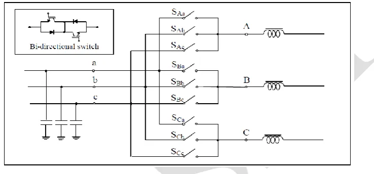
The matrix converter consists of 9 bi-directional switches that allow any output phase to be connected to any input phase. The circuit scheme is shown in Fig.1. The input terminals of the converter are connected to a three phase voltage-fed system, usually the grid, while the output terminal are connected to a three phase current- fed system, like an induction motor might be. The capacitive filter on the voltage- fed side and the inductive filter on the current- fed side represented in the scheme of Fig. 1 are intrinsically necessary. Their size is inversely proportional to the matrix converter switching frequency [2]. It is worth noting that due to its inherent bi-directionality and symmetry a dual connection might be also feasible for the matrix converter: a current- fed system at the input and a voltage- fed system at the output.
Fig. 1 Circuit scheme of a three phase to three phase matrix converter
The modulation strategy is based on a desired output voltage magnitude and frequency and an input displacement factor. The matrix converter will be modeled by its output voltages and input currents in terms of switching functions of the switches as follows:
(1)
(2)
The switching functions in Eq. 1 and2 are defined as:
In order to avoid short-circuited input terminals and open-circuited output phases, these switching functions should satisfy the following constraint equation:
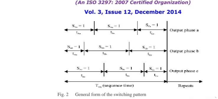
The shape of the switching functions depends on the switching pattern used; a typical switching pattern is shown in Fig.
2. By considering that the bidirectional power switches work with high switching frequency, a low-frequency output
ISSN: 2319-8753
I
nternational
J
ournal of
I
nnovative
R
esearch in
S
cience,
E
ngineering and
T
echnology
(An ISO 3297: 2007 Certified Organization)
Vol. 3, Issue 12, December 2014
Fig. 2 General form of the switching pattern
The switching frequency is usually greater than 20 times, the output frequency in order to obtain an output voltage with low harmonic. The low-frequency transfer matrix also known as modulation matrix:
(3)
Where:
(4)
The constraint equations for the matrix converter can be written as
(5)
There are several modulation techniques used to obtain the modulation matrix, M (t) such as Venturini method, Venturini optimum method, Scalar method and Space vector modulation method. In this study, the Venturini and Venturini optimum methods will be used. When the voltage gain ratio, q is ≤0.5 for unity input displacement factor, the modulation duty cycles can be obtained using the Venturini method from the following compact form
For:
(6)
Where vk denotes the input voltages which are given by:
(7)
and vj denotes the reference output voltages which are given by:
(8)
When the voltage gain ratio, q is greater than 0.5 and for unity displacement factor, the modulation duty cycles
can be obtained using the Venturini optimum method from the following compact form
(9)
for K = A, B, C; j = {a, b, c}; βK = 0, 2π/3, 4π/3 for K = A, B, C, respectively. The reference output voltages, vj are
ISSN: 2319-8753
I
nternational
J
ournal of
I
nnovative
R
esearch in
S
cience,
E
ngineering and
T
echnology
(An ISO 3297: 2007 Certified Organization)
Vol. 3, Issue 12, December 2014
(10)
Inductive load model: The inductive load will be modeled in terms of the load current differential equation given by: (11) where:
R and L are the load resistance and inductance.
III.SPACEVECTORREPRESENTATIONOFATHREEPHASESYSTEM
A generic three-phase electrical system consists of a set of three voltages and three currents interacting with each other to deliver electrical power. A practical three-phase system cannot be considered as the simple addition of three independent single-phase subsystems. Actually, particular relations exist between the phase variables of a three-phase system, such as those resulting from the Kirchhoff laws or regarding phase sequences, which invite the application of certain space vector transformations to obtain a more elegant and meaningful representation of its variables. Generally, the control system of a power converter connected to a three-phase system is based on these transformed variables. This appendix reviews the most commonly used space vector transformations and highlights their applications in control grid-connected power converters.
a. MODULATION ALGORITHM
The space vector algorithm is based on the representation of the three phase input current and three phase output line voltages on the space vector plane. In matrix converters, each output phase is connected to each input phase depending on the state of the switches. For safe switching in the matrix converter;
• Input phases should never be short-circuited,
• Owing to the presence of inductive load, the load currents should not be interrupted at any switching time. There are 27 different switching combinations for connecting output phases to input phases if the above two rules are provided. These switching combinations can be analyzed in three groups. Each output phase is directly connected to three input phases in turns with six switching combinations in the first group. In this case, the phase angle of output voltage vector depends on the phase angle of the input voltage vector. Similar condition is also valid for current vectors. For the space vector modulation technique, these switching states are not used in the matrix converter since the phase angle of both vectors cannot be controlled independently. There are 18 switching combinations in the second group in which the active voltage vector is formed at variable amplitude and frequency.
b. SPACE VECTOR APPROACH FOR MATRIX CONVERTER
ISSN: 2319-8753
I
nternational
J
ournal of
I
nnovative
R
esearch in
S
cience,
E
ngineering and
T
echnology
(An ISO 3297: 2007 Certified Organization)
Vol. 3, Issue 12, December 2014
Fig: 3 Three-phase to three-phase matrix converters
Research on the matrix converter has mainly focused on modulation schemes and the digital generation of the PWM switching patterns. A conventional matrix converter (CMC) utilizes nine bidirectional, bipolar (four-quadrant) switches that, when based on available power semiconductor technology, are constructed using 18 unipolar turn-off power semiconductors (IGBTs) and 18 diodes With reference to the matrix converter and the relevant symbols shown in Fig.3 and accordingly, it is possible to define the following space vectors:
where vi(t), vo(t) , ii(t) and io(t) are the time dependent magnitudes of the space vectors while ai(t), ao(t) , bi(t) and bo(t)
are the corresponding time dependent phase angles. Now, these four space vectors can be defined for any matrix converter switches configuration (in the following also simply configuration). But not all the possible configurations that a matrix converter can assume can be usefully employed.
IV. INDIRECT SPACE VECTOR MODULATION
A space vector is obtained from three phase quantities through the following transformation:
ISSN: 2319-8753
I
nternational
J
ournal of
I
nnovative
R
esearch in
S
cience,
E
ngineering and
T
echnology
(An ISO 3297: 2007 Certified Organization)
Vol. 3, Issue 12, December 2014
V. SPACE VECTOR MODULATION FOR THE INVERTER STAGE
The inverter can be assumed as a separateVSI. The switching method is exactly similar to conventional VSI [6], but owing to its virtual DC link, VDC should be defined as follows:
Vin is the peak value of input voltage, and θin is the input displacement angle.
The inverter switches have eight permitted combinations to avoid a short circuit. These combinations include three zero and six nonzero input currents. The reference output voltage vector is synthesized by impressing the adjoining active vectors Vα and Vβ with theduty cycles dα and dβ, respectively. The reference vector can be expressed by the voltage-time product sum of the adjoining active vectors as illustrated in Figure 4:
The duty cycles of the active vectors can be written as:
where θv indicates the angle of the reference voltage vector and mv is the voltage modulation index
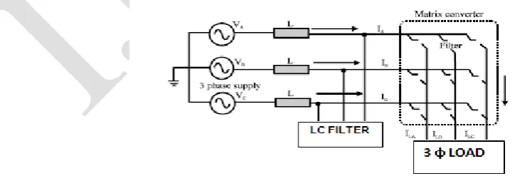
VI. THE INPUT FILTER
Harmonic current pollution of three-phase electrical power systems is becoming a serious problem due to the wide use of nonlinear loads, such as diode or thyristor rectifiers and a vast variety of power electronics based appliances. Traditionally, passive LC filters have been used to eliminate the current harmonics and to improve the power factor. However, passive LC filters are bulky, load dependent and inflexible. The reason for this choice is the simplicity of passive LC filters and their potential to meet the desired specifications with higher efficiency, smaller size and lower cost than an active solution. The input filter presented in Fig.3 connects the utility grid to the matrix converter through three inductors with inductance L. capacitors C provide a low impedance path for the high frequency ripple current and thus attenuate the content of current ripple in the utility current. The filter capacitors are Y-connected to a virtual neutral point so that it is reduced the voltage rating of the capacitors.
ISSN: 2319-8753
I
nternational
J
ournal of
I
nnovative
R
esearch in
S
cience,
E
ngineering and
T
echnology
(An ISO 3297: 2007 Certified Organization)
Vol. 3, Issue 12, December 2014
VII. SIMULATION RESULTS
In this work, three-phase matrix converter based LC filter is used to compensate the current harmonics. The source voltage is 440Vrms, 60Hz. The source impedance parameters L and C values for passive branches used. The system has been simulated without filter, existing shunt active filter and the proposed matrix converter based active filter separately. The simulation is performed by the Matlab Simulink model in discrete form. Figure 6 shows the voltage and current waveforms without filter. Figure 7 shows that its total harmonic distortion. Figure 8 shows the voltage and current waveforms without filter. Figure 9 shows that its total harmonic-distortion.
Fig 5: voltage and current waveforms without filter Fig 6: Total Harmonic Distortionn without filter
The output waveforms are observed, and it is seen that there is a considerable amount of harmonics present in the load. This is mainly because that the matrix converter is sensitive to input voltage disturbances and also with the matrix converters, the output voltage range is less than the input voltage. The simple matrix converter has a maximum input output transfer ratio of 87% for sinusoidal input-output.
Fig 7: voltage and current waveforms with filter Fig 8: Total Harmonic Distortionn with filter
To reduce the total harmonic distortion, we designed an Inductive-Capacitive filter. This filter is placed in the input side of the circuit. The filter is designed to a low pass one, which allows only the low order harmonic to pass. Using FFT transformation, the harmonics is viewed, and is noted that is considerably reduced to 1.79% from the previous of 23.78%.
VIII.
CONCLUSIONISSN: 2319-8753
I
nternational
J
ournal of
I
nnovative
R
esearch in
S
cience,
E
ngineering and
T
echnology
(An ISO 3297: 2007 Certified Organization)
Vol. 3, Issue 12, December 2014
REFERENCES
[1] Wheeler J, Rodríguez PW, Clare JC, Empringham L,Weinstein A (2002) Matrix converters: a technology review. IEEE Trans Ind Electr 49:276– 288
[2] A. Alesina, M. Venturini, “Analysis and Design of Optimum-Amplitude Nine-Switch Direct AC-AC Converters”, IEEE Transactions on Power Electronics, Vol. 4, no. 1, pp. 101-112, January 1989.
[3] D. Casadei, G. Grandi, G. Serra, A. Tani, “Space vector control of matrix converters with unity input power factor and sinusoidal input/output waveforms,” Proceedings of IEEEPE' 93, Vol. 7, pp. 170-175, 1993.
[4] E. Yamamoto, T. Kume, H. Hara, T. Uchino, J. Kang, and H. Krug, “Development of matrix converter and its applications in industry,” in Proc. 35th IEEE IECON, Porto, Portugal, 2009, pp. 4–12.
[5] G. Roy and G.-E. April, “Cycloconverter operation under a new scalar control algorithm,” in Proc. 20th Annu. IEEE Power Electron. Spec. Conf., Jun. 1989, vol. 1, pp. 368–375.
[6] H.W. van der Broeck, H. Ch. Skudelny, and G. V. Stanke, “Analysis and realization of a pulse widthmodulator based on voltage space vectors,”
IEEE Transactions on Industry Applications, vol. 24, no. 1, pp. 142–150, 1988.
[7] M. Jussila and H. Tuusa, “Comparison of direct and indirect matrix converters in induction motor drive,” in Proceedings of the 32nd Annual Conference on IEEE Industrial Electronics
(IECON ’06), pp. 1621–1626, Paris, France, November 2006.
[8] L. Huber and D. Borojevic, “Space vector modulated three phase to three-phase matrix converter with input power factor correction,” IEEE Transactions on Industry Applications, vol. 31, no. 6, pp. 1234–1246, 1995.
[9] M. Rivera, R. Vargas, J. Espinoza, and J. Rodriguez, “Behavior of the predictive DTC based matrix converter under unbalanced AC-supply,” in