© 2015, IRJET.NET- All Rights Reserved
Page 1069
Comparative Study of Air Carbon Arc Gouging Process on Sae 316
Stainless Steel
Anoop G Das
1, R. Abarna
21
M.E Student, Dept of Mechanical Engineering, Gnanamani college of Technology, T N, India
2
Assistant Professor, Dept of Mechanical Engineering, Gnanamani college of Technology, T N, India
---***---Abstract-
Gouging or cutting is the process of when the intense heat of the arc between the carbon electrode and the work piece melts part of the work piece. Simultaneously, air passes through the arc quickly enough to blow the molten material away. Indian shipping industry is heavily using this technique for various aspects. The main aim of gouging technique is the removal of welds. The study aims at the process capability of gouging process and its comparison with conventional cutting method to prove, which process has more draw backs and which is more advantageous in comparison to each other. SAE 316 stainless steel is used as the base metal for comparative study. The work aims to study about the weldablity of air carbon arc gouging over welded 316 stainless steel. The study also includes the mechanical properties, elemental composition, and microstructure analysis of gouged and welded metal and also makes a comparative evaluation of gouging process with conventional cutting. Shipping industry is heavily using various classes of stainless steel for variety of applications. Also the present work is applicable not only for the shipping industry but also for automobiles, boiler, power plants etc.Key words
;
Air Carbon Arc (ACA) Gouging, Manual MetalArc (MMA Gouging)
1
. INTRODUCTION
Gouging is a method used to melt or fuse metals in a narrow groove. Air Carbon Arc (ACA) Gouging or cutting occurs when the intense heat of the arc between the carbon electrode and the work piece melts part of the work piece. Simultaneously, air passes through the arc quickly enough to blow the molten material away. Indian shipping industry is heavily using air carbon arc gouging technique for various aspects. The common cutting technique employed in our workshop and mechanical industry is power hacksaw cutting [1]. So the analysis over these two processes must be needed scientifically to explain which process is better in material removal.
Gouging electrodes are made of mixing carbon/graphite with a binder, baking, and then coating with a controlled thickness of copper. Carbons are available in three types:
The air carbon arc process is flexible, efficient, and cost effective on practically any metal; carbon steel, stainless steel and other ferrous alloys; gray, malleable and ductile cast iron; aluminum; nickel; copper alloys and other nonferrous metals. Single-phase machines with low open-circuit voltage may not work for air carbon arc gouging (CAC-A). However, any three-phase welding power source of sufficient capacity may be used for air carbon arc gouging. The arc voltage used in air carbon arc gouging and cutting ranges from a low of 35 to a high of 56 volts; thus the open-circuit voltage should be at least 60 volts. and 100 psi at the torch; higher pressures may be used, but they don’t remove metal more efficiently. Use 60 psi (413.7 kPa) with the light-duty
Least 3/8" (6.4 mm).
Gouging electrodes are made of mixing carbon/graphite with a binder, baking, and then coating with a controlled thickness of copper. Carbons are available in three types:
Pointed, Jointed and Flat Pointed Carbon are the standard all purpose gouging electrode. Controlled copper coating improves electrical conductivity, providing more efficient, cooler operation and helps maintain electrode diameter at the point of the arc. Jointed carbons have the added benefit of working without stub loss; with each rod have a female socket and matching male tang. They can be used with semi and fully automatic torches. Flat carbons are specially designed for close tolerance metal removal and producing a rectangular groove.
© 2015, IRJET.NET- All Rights Reserved
Page 1070
process is flexible, efficient, and cost effective onpractically any metal.
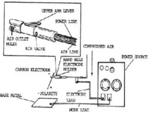
Fig.1 Air carbon arc gouging
1.1
GOUGING ELECTRODE
Gouging electrodes are made of mixing carbon/graphite with a binder, baking, and then coating with a controlled thickness of copper. Carbons are available in three types: Pointed, Jointed and Flat.
Pointed Carbon are the standard all purpose gouging electrode. Controlled copper coating improves electrical conductivity, providing more efficient, cooler operation and helps maintain electrode diameter at the point of the arc. Jointed carbons have the added benefit of working without stub loss; with each rod have a female socket and matching male tang. They can be used with semi and fully automatic torches. Flat carbons are specially designed for close tolerance metal removal and producing a rectangular groove.
The gouging electrode carbons are used for the efficient gouging, plate edge preparation, touching up and removal of old or defective hard facing and stainless steel weld deposits. They are used for reworking plates, dies, castings, pipes etc.
They gouge and sever ferrous and non-ferrous metals such as carbon steel low alloy steel, stainless steel, cast iron, nickel alloys (nickel lessthan 80%), magnesium alloys and aluminum on DCEP. Copper alloys, aluminum bronze alloys and aluminum nickel bronze alloys can be gouged using DCEN
.
Fig.2 Gouging electrode
2. LITERAUTRE SURVEY
2. 1 Important studies on gouging
A new correlation of the gouging technique over steel samples and a comparative cutting technique is experimentally analyzed with some reference of past experiments
Goerge R Zamboldi and Valery A Nolan[1]studied and led to the invention of gouging rod made of carbon which is extremely helpful in steel Industry for precise cutting and cleaning of steel. It is the practice to make such rods by mixing carbonaceous material with suitable binders and processing the mixture at suitable temperature. The rods are copper coated and are well known product in the gouging industry now.
MichioAmbe ,Kalzu Gun , Gifu Ken studied and patented the use of carbon rod assemblies for arc gouging of steel . An uninterrupted copper coating is presented on the exterior of each rod inclusing the inner wall of the socket and outer surface of the projection, this invention is relates to a carbon rod assembly which is useful as an electrode for gouging or blasting of steel. when using such carbon electrode for gouging the surface of a steel article, the electrode is gripped by a suitable holder through which electric current is supplied to the electrode to strike an arc between the tip of the electrode and the surface of steel article or work piece to melt the surface metal, the molten metal being blown away by a high pressure air supplied by the holder.
© 2015, IRJET.NET- All Rights Reserved
Page 1071
provide the reference to find the weld ability after gougingby testing the metal sample at the cutting region
Dearden and O'Neil studied in detail about the elemental analysis over steel and the mechanical property relationship in concern with the equivalent carbon content and various low carbon steel and carbon manganese steel are analyzed and their properties are studied. The carbon equivalent is a measure of the tendency of the weld to form martensite on cooling and to suffer brittle fracture. When the carbon equivalent is between 0.40 and 0.60 weld preheat may be necessary. When the carbon equivalent is above 0.60, preheat is necessary, post heat may be necessary.
J Nicholou, D Papimitiriuo[14] studied and patented on the topic slag and fume collector for air carbon arc gouging and gouging torches, this inventions pertains to the field of collecting fume or waste particulate matter generated by air carbon arc gouging. The air carbon process prepares the metals for finishing purposes like in welding. The molten metal or slag produced by arc is forcibly removed from the surface by a stream of high pressure air directed along the electrode towards the arc. This creates a large amount of fumes, which may pollute the surroundings. The invention is providing a lot ways to restrict the formation of fumes and slag collections upon the surface of metal. The micro structure and mechanical property variations are also studied in later stages by these two.
3. EXPERIMENTAL WORK
3.1 materials
The base metal selected for experimental analysis is SAE 316 stainless steel. They are taken in size of 100 mm x 50 mm x 10 mm and also 10 mm diameter cylindrical rods. The test specimen for the experimental analysis was prepared as per ASTM standard. The experiment analysis includes testing of the mechanical properties and elemental composition of gouged and welded metal and also makes a comparative evaluation of gouging process with conventional cutting.
3.2
Equipment
Three-phase welding power source of sufficient
capacity may be used for air carbon-arc gouging. The open-circuit voltage should be higher than the required arc voltage to allow for a voltage drop in the circuit. The arc voltage used in air carbon-arc gouging and cutting ranges from a low of35V (volts) to a high of 56V; thus, the open-circuit voltage should be at least 60V.
The actual arc voltage in air carbon-arc gouging and cutting is governed by arc length and the type of gouging. ACA is used with DCEP (reverse polarity).The electrode should extend at most 7" (178 mm) from the gouging
torch, with the air jet between the electrode and work piece. Use a minimum extension of2" (50,8 mm). Torch parts will damage if the stick out of the electrode is less than the 2" (50,8 mm).
Fig 3. ACA gouging circuit block diagram
arc is struck with an electrode which is held at a normal angle to the workpiece (15 degrees backwards from the vertical plane in line with proposed direction of gouging). Once the arc is established, the electrode is immediately inclined in one smooth and continuous movement to an angle of around 15-20 degrees to the plate surface. With the arc pointing in the direction of travel, the electrode is pushed forward slightly to melt the metal. It should then be pulled back to allow the gas jet to displace the molten metal and slag. This forward and backward motion is repeated as the electrode is guided along the line to complete the gouge.
© 2015, IRJET.NET- All Rights Reserved
Page 1072
Fig.5 vertical gouging
To produce a consistent depth and width of gouge, a uniform rate of travel must be maintained, together with the angle of electrode: 10-20 degrees. If the electrode angle becomes too steep, in excess of about 20 degrees, the amount of slag and molten metal will increase. This is a result of the arc penetrating too deeply. Digging the electrode into the metal causes problems in controlling the gouging operation and will produce a rough surface profile.
Use ordinary compressed air for air carbon-arc gouging. Normal pressures range between 80 psi (551.6 k Pa) and 100 psi (690 k Pa) at the torch; higher pressures may be used, but they do not remove metal more efficiently. Use 60 psi (413.7 k Pa) with the light-duty manual torch. Do not use pressures this low with general duty torches. Regardless of the pressure used with manual torches, the air hose, supplying air to the cable assembly connected to the torch body, should have an inside diameter(ID) of at least 3/8" (6,4 mm).Mechanized torches with automatic arc-length control should have an air-supply hose with a minimum ID of 1/2" (12 mm).
4.RESULTS AND DISCUSSION
4.1. CHN Analysis
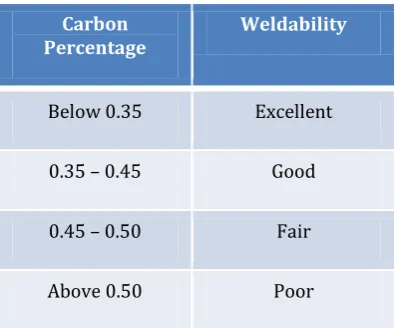
CHN Analysis is a form of Elemental Analysis concerned with determination of only Carbon (C), Hydrogen (H) and Nitrogen (N) in a sample. The most popular technology behind the CHN analysis is combustion analysis where the sample is first fully combusted and then the products of its combustion are analyzed. The work piece were cut using gouging and those portions of heat affected zone( HAZ) are machined and collected in the form of fine powder by grinding and filing. Those collected being 5.5 gm is given for CHN analysis test, so that we can easily predict the weld ability [3] nature of these metal after cutting using Dearden and O’neil table as follows.
Fig.6 CHN measurement flow diagram
Table -1: Weldability table
Carbon Percentage
Weldability
Below 0.35 Excellent
0.35 – 0.45 Good
0.45 – 0.50 Fair
Above 0.50 Poor
Table -2: Carbon percentage in SAE 316 stainless steel
Sample No:
Carbon Percentage
Remarks
1 0.34 Excellent weldability 2 0.33 Excellent
weldability 3 0.33 Excellent
weldability
© 2015, IRJET.NET- All Rights Reserved
Page 1073
4.2 Impact strength (charpy impact test)
Impact strength is the capability of the material to withstand a suddenly applied load. The test is conducted for the three samples of SAE 316 stainless steel. A specimen of 10mm×10mm×55mm size is used for Charpy impact testing. The base metal is cut using arc gouging and then welded it using electric arc welding. The test has also being conducted over conventionally cut and welded specimen. The test consist of measuring the energy absorbed in breaking a ASTM standard notched specimen by giving a single blow by swinging hammer. The specimen is simply supported at its ends. As the velocity of striking body is changed, there must occur a transfer of energy; work is done on the parts receiving the blow.
The specification of charpy machine [5] used for the toughness test of present work is as follows.
Weight of hammer 20 kg
Striking of hammer 5 cm / s to 5.5 cm / s
Angle of hammer striking edge 300
Radius of curvature of striking edge 2 mm
Swing of hammer both ways 0 – 1600
Table -3: Air Carbon Arc Gouging
Sample No: Impact strength ( Nm)
1 66.7
2 66.5
3 66.6
Average impact strength in ACA gouging = 66.6 Nm
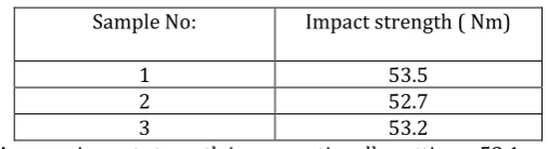
Table -4: Conventionally Cutting
Sample No: Impact strength ( Nm)
1 53.5
2 52.7
3 53.2
Average impact strength in conventionally cutting = 53.1 Nm
4.3. Abrasive Wear Test
Abrasive resistance is a property which allows a material to resist scraping, rubbing, and other types of mechanical wears. Pin on disc machine is used for testing the Abrasive wear resistance of the specimen.A specimen of 40 mm× 25 mm× 10mm size is used for abrasive wear test. The sample was mounted perpendicularly on a stationary vice such that its one of the face is forced to press against the abrasive that is fixed on the revolving
disc. Hence it is the abrasive paper that tends to wear the surface of the samples. When the disc rotates for a particular period of time, the sample can loaded at the top to press against the disc with the help of a lever mechanism. In this experiment the test can be conducted with the following parameters
(1) Load (2) Speed (3) Time
Load-15 N , RPM -500, Time- 5 Minutes, Type of Abrasive- Emery, 80 grade size.
The wear rate of each specimen was calculated from the mass loss.
wear volume, wear rate and wear resistance can be calculated as follows.
Wear volume = weight loss / density
Density of specimen, AISI 316= 7.99 g /cm3
Wear rate =wear volume / sliding distance(s)
Sliding distance (s) = V x time = (2 π R N / 60) x time
Where, R = radius of abrasive wheel (7.25cm), N= 300 rpm
Time = 5 minute ,wear resistance = 1 / wear rate.
Table -5 Air Carbon Arc Gouging Weight loss (gm) Wear resistance(cm2 x 10-7 )
0.18 0.303
0.19 0.288
0.17 0.322
Average wear resistance in ACA gouging = 0.304
Table - 6 Conventionally cutting
Weight loss (gm) Wear resistance(cm2 x 10-7 )
0.21 0.261
0.22 0.248
0.21 0.261
Average wear resistance in conventionally cutting= 0.256
© 2015, IRJET.NET- All Rights Reserved
Page 1074
heavily depend upon the load applied, as the load appliedincreases, the wear rate increases linearly 4.4. Hardness Test
Hardness is the resistance of metal to plastic deformation, usually by indentation
D = diameter of indenter (mm)
D= diameter of indentation (mm)
P = 187.5N, D = 2.5mm
Table -7 Air Carbon Arc Gouging
Diameter of indentation (mm) Hardness value
1.0 mm 228.76
ACA gouged pieces has more hardness than conventionally cut pieces.
5. CONCLUSION
Weldability of SAE 316 Stainless steel can be improved by using air carbon arc gouging process. So a better welding can be capable of gouged metal pieces. The impact strength of air carbon arc gouged SAE 316 Stainless steel is higher than that of conventionally cut piece.
A material wear resistance rate is its main property for its prolonged use in various applications. Here even at a room temperature and for a common load, the wear resistance is more for air carbon arc gouged SAE 316 Stainless steel. The corrosive nature after can also be predicted from its nature of wear resistance. Air carbon arc gouged pieces has more hardness than conventionally cut pieces
[2].Rao P. N, ”Manufacturing Technology”, 2nd Edn. , Tata McGraw Hill Publisher, NewDelhi, 2003, p – 28, 13 – 20 [3]. Johan Evander,“ New aristo wire feeders for shipping
industry,” SVETSAREN ,cutting and welding journal, vol .61, no.1 ,2006 for metals”,Tribology International, 30 ( 1997 ) : pp. 377 – 383
[7] S Satapathy, C Persad, R Monfredo Gee, S Bless ,” Gouging induced fractures in tungsten long rods”, International journal of impact engineering,29(2003), 621-630
[8] Antonio Augusto Gorni (2006): ‘steel forming and heat treatment hand book’,3rd version, august 2006
[9] Arc air global brand(2004): ‘Air carbon arc guide’ ,Dec 2004
[10]Hsu S. M., Shen M. C. and Ruff A. W (1997): ‘Wear prediction for metals’, Tribology International, Vol 30, 1997, pp. 377 – 383.
[11] Izciler M. and Tabur M (2006): ‘Abrasive wear behaviour of different case depth AISI gear steel, Wear’, Vol 220, 2006, pp. 90 – 98.
[12] Johan Evander, ‘New aristo wire feeders for shipping industry’, Svetsaren cutting and welding journal, vol .61, no.1 ,2006
[13]Moore M. A, ‘Abrasive wear, Materials in Engineering Applications’, 1978: pp. 97– 111.
[14]Nicholou, DPapimitiriuo (2008), ‘Microstructures and mechanical properties after heating of reinforcing 500 MPa class weldable steels produced by various processes, micro alloyed with vanadium and work-hardened’, 2008 [15]Rao P. N, ‘Manufacturing Technology’, 2nd Edn. , Tata McGraw Hill Publisher, New Delhi, 2003, p – 28, 13 – 20. [16] Robert Fernicoila (2006) , ‘practical welding’, vol 10, no 3, June 2006