R E S E A R C H
Open Access
Area-classified interference coordination for
heterogeneous cellular network
Yongming Huang
1,2*, Shiwen He
1, Shi Jin
1, Luxi Yang
1, Lei Jiang
3and Ming Lei
3Abstract
In this paper, we aim to address the cross-layer interference in the heterogenous cellular network (HetNet). In order to exploit the overlapping characteristics of the HetNet coverage and achieve a good trade-off between the interference coordination gain and the cost, an area-classified interference coordination strategy is first proposed. The basic idea is that coverage of the HetNet is classified into four different areas such that area-specific interference coordination can be used to increase the cross-layer cooperation efficiency. A new steepest slope method based on relative cooperation gain is proposed to realize efficient area classification. Then, a coordinated beamforming scheme based on area-specific limited feedback is proposed to examine the effectiveness of this new strategy. It is shown that the proposed scheme could increase the success rate of user pairing and thus improve the throughput performance, with reduced feedback overhead in contrast to existing schemes. Its effectiveness is finally verified via numerical simulations.
Keywords: Heterogenous cellular network (HetNet); Cross-layer interference; Coordinated beamforming; Limited feedback
1 Introduction
Driven by the development of new wireless user equip-ments (UEs) and the proliferation of bandwidth-intensive applications, traffic load in cellular networks will increase in an explosive manner. The use of conventional cellular network framework is difficult to meet the new demands. To solve this issue, recently, a new framework called het-erogeneous network (HetNet) has emerged as a flexible and cost-effective solution [1-4]. It is realized by overlay-ing lower-power access points such as relay node, picocell base station (BS), femtocell BS, and remote radio head (RRH) in the coverage of macrocell [5-7]. It is shown in [8] that the integration of the cross-layered macrocells and femtocells promises to significantly improve the area spectral efficiency of cellular network. Recently, the distri-bution of the achievable signal-to-interference-noise ratio (SINR) of the HetNet is derived in [9], and the achiev-able throughput of the HetNet is also analyzed in [10], both revealing that the HetNet has a potential of greatly
*Correspondence: [email protected]
1School of Information Science and Engineering, Southeast University, Nanjing 210096, China
2Key Laboratory of Broadband Wireless Communication and Sensor Network Technology (Nanjing University of Posts and Telecommunications), Ministry of Education, Nanjing 210003, China
Full list of author information is available at the end of the article
improving the system performance in contrast to the conventional homogeneous cellular network.
In order to fully exploit the benefit of the lower-power nodes in the HetNet, a method of cell range expansion is developed. It is realized by adding a positive bias value to the lower-power node in the cell selection process; by this, it means that more users can associate to the lower-power node cell even if the lower-lower-power node is not of the strongest signal. This method is useful for the load balancing and the exploitation of spatial reuse, and it also helps to mitigate the uplink (UL) inter-cell interference by reducing the UL transmit power [11-14]. However, in the downlink phase, the UEs in the range expansion area will suffer severe cross-layer interference from the macrocell base station (MBS). Therefore, it is important to develop new interference coordination technology for the HetNet. In the 3GPP long-term evolution (LTE) R10 standard specification, a specific subframe called almost blank sub-frame (ABS) is adopted to partially address this problem. Since the MBS is kept silent within ABSs, the users in the lower-power node cell can be allocated without suffer-ing strong macrocell interference within ABSs. However, the effective use of ABSs requires the lower-power nodes to have perfect knowledge of the ABS patterns such that they can make a proper user scheduling [11-14]. Besides
this approach, interference control (IC) based on lim-ited feedback of channel information, such as the best companion cluster (BCC) technology [15,16], recently has also been intensively studied and applied in the HetNet [17-20]. In [17], an adaptive strategy is proposed which uses joint beamforming to address the inter-cell interfer-ence between scheduled users only when the interferinterfer-ence is significant. In [18], a prioritized selection (PS)-based IC scheme is developed. Furthermore, the performance of low-complexity random beamforming transmission with user scheduling in the same scenarios is analyzed in [19]. Later, a joint selection (JS)-based IC is presented to achieve more balanced performances between the macro-cell users and the RRH macro-cell users [20], which is efficient especially when the number of users is sufficiently large. However, it should be noted that this scheme requires that each user feeds back the preferred matrix index (PMI) and the best companion cluster index in a predetermined codebook, causing increased feedback overhead and lim-iting the freedom degree for user pairing. More recently, an efficient IC scheme based on heterogenous limited feedback is proposed, which fully exploits the inherent heterogeneous structure of user density and large-scale channel effects [21]. Furthermore, a distributed schedul-ing policy based on the cumulative distribution function of the channel quality indicator is designed and analyzed for the HetNet [22]. Also, new interference alignment approaches are proposed to solve the inter-cell interfer-ence of the HetNet [23,24]. In addition, radio resource allocation is also an important issue for the HetNet, which has attracted much attention. In [25], the authors propose a radio resource allocation framework for the HetNet and derive a resource allocation strategy that is asymptotically optimal on the proportional fairness metric.
In contrast to the homogeneous network, the ratios of the interference level to the desired signal strength for the users randomly distributed in a HetNet vary in a much broader range. This is due to the fact that the lower-power nodes are overlaid in the macrocell. As a result, direct application of conventional interference coordina-tion approaches in a HetNet usually has low efficiency. In this paper, different from previous works which focus on specific interference coordination scheme design based on a fixed or simple cooperative region, we study a new interference coordination strategy by exploiting an adap-tive cooperation region. We propose to first classify the coverage of HetNet into a couple of areas based on coor-dination efficiency. Users located in different areas have different coordination requests and feedback different channel information so as to improve the coordination efficiency. A new method is then proposed to realize an efficient area classification, and as a particular applica-tion, an area-classified spatial interference coordination scheme based on limited feedback is further developed,
which has a much increased success rate of user pairing and thus improves the throughput performance. Simula-tion results finally show that the proposed scheme out-performs the conventional schemes even with reduced feedback overhead.
2 System model
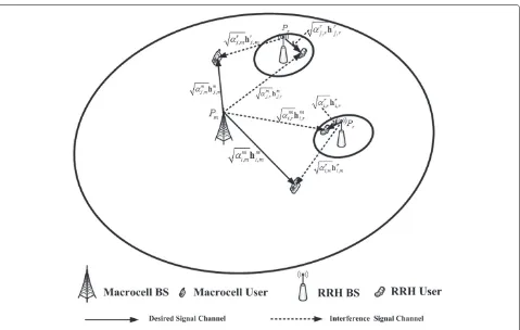
Consider a HetNet consisting of one MBS and several overlaid lower-power nodes (henceforth, we use RRHs as example). Assume that the MBS is equipped with Ntm antennas; each RRH BS is equipped withNtrantennas and each user is equipped with a single antenna, as shown in Figure 1. In general, each BS serves its own users in an orthogonal way via orthogonal frequency-division mul-tiple access (OFDMA) or time division mulmul-tiple access (TDMA). Assume that the RRH BSs are well deployed such that their coverage has no obvious overlapping, therefore the interference between the RRH cells can be ignored. However, there exists severe cross-layer inter-ference between the macrocell and the RRH cells due to coverage overlapping. To address this issue, the MBS and the RRH BS are designed to perform coordinated trans-mission on the same time-frequency resource such as a single subcarrier or a couple of neighboring subcarriers in the OFDMA system, where the MBS and the RRH BS each serves a single user and design their transmit beam-forming vectors cooperatively. Without loss of generality, we assume that the macrocell useriand RRH cell useri in the HetNet are simultaneously active on the same time-frequency resource, with their received signalymi andyri are written respectively as
ymi =Pmαmi,m
wherePmandPr denote respectively the transmit power
of the MBS and the RRH BS,αri,mandαim,r denote respec-tively the large-scale fading coefficients from the RRH BS to macrocell user i and from the MBS to RRH cell useri,hri,mandhmi,rdenote respectively the small-scale flat Rayleigh fading channels from the RRH BS to macrocell useriand from the MBS to RRH cell useri, wmi andwri denote respectively the beamforming vectors employed by the MBS and the RRH BS,xmi andxri denote respectively the information symbols intended for macrocell useriand RRH cell user i, andnmi andnri denote respectively the additive Gaussian white noise at the macrocell user and the RRH cell user, both with zero mean and varianceσ2.
Figure 1Illustration of the heterogenous network.
is by cooperatively designing the beamforming vectors {wri,wmi } and allocating the transmit powers [26-28]. This requires the exchange of channel state information (CSI) of the users between the MBS and the RRH BS. In fre-quency division duplex (FDD) systems, the CSI should be fed back from the users using the methods such as [29,30] and then shared between the BSs, causing a large over-head. Though this problem has been intensively studied for the homogeneous network in the literature, the wide range of the SINR distribution resulting from heteroge-nous deployment has not been well exploited to reach a good trade-off between the coordination gain and the overhead.
3 Area-classified interference coordination Due to the fact that RRH cells are overlaid in the macro-cell, in general, all the RRH cell users suffer interference from the MBS. However, the users in different areas usually have significantly distinct orders of signal-to-interference ratios (SIRs). Therefore, it is not efficient to employ a uniform interference coordination over all areas. In particular, performing interference coordination on the users with high SIRs usually brings marginal gain but requires additional cost such as the feedback of interfer-ence channels. The same issue exists in the macrocell. To improve the coordination efficiency, we propose to
classify both the macrocell coverage and RRH cell cov-erage into two types of areas, i.e., the cooperative area and non-cooperative area. The interference coordination is only used for the users located in the cooperative area.
To mathematically illustrate this idea, let Am andAr
denote the cooperative areas of the macrocell and the RRH cell, respectively. LetRmICandRrICdenote respectively the rates of the macrocell user and the RRH cell user in the cooperative area achieved using interference coordi-nation such as the zero-forcing beamforming, andRmWIC andRrWICdenote the rates achieved without using inter-ference coordination, where the MBS and the RRH BS design their transmit beamforming vectors independently based on local CSI. Then, the relative cooperation gains (RCG) of the macrocell user and the RRH cell user are defined respectively as
Gm c =
RmIC−RmWIC
RmWIC , (3)
Gr c=
RrIC−RrWIC
RrWIC . (4)
the coordination efficiency, the area classification is deter-mined by solving the following optimization problem:
max denotes the expectation operator over the cooperative area, andgthm andgthr denote the minimum GCR require-ments of the macro and RRH cooperative areas, respec-tively.
It is difficult to directly solve the above optimization problem due to the fact that the closed-form expres-sion of the average relative cooperation gain is hard to achieve. Alternatively, we propose to classify the cell cov-erage according to the reference signal receiving power (RSRP), where the RSRP is defined as the received power at the user terminal measured from the cell-specific ref-erence signal within the considered frequency bandwidth. By this means, the cooperative area can be represented by a couple of parameters and has fewer drawbacks to deter-mine. Before introducing the detailed method, we first provide some numerical results to illustrate some useful observations.
Figure 2 illustrates the values of the macrocell RSRP and the RRH cell RSRP of a user varying its position within the distances 30∼190 m to the macro BS, where the distance between the macro BS and the RRH is 200 m.
It is seen that the difference between the macrocell RSRP and the RRH cell RSRP is less than 5 dB only when the user has a distance of 160 ∼ 180 m to the macro BS, where the cross-layer interference is severe and the coordinated beamforming is necessary. In other cases, a cooperation between the macro and RRH BSs may not promise a large gain.
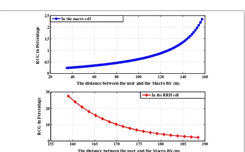
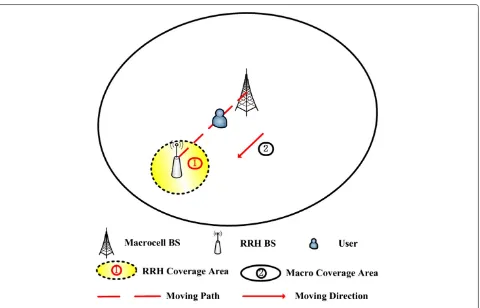
Figure 3 shows the variation of the relative cooperation gain of a user who moves from the macrocell center to the RRH cell center as shown in Figure 4. It can be seen that the relative cooperative gain monotonically decreases when the user moves from the macro (RRH) cell edge to the center, with a reduced decreasing rate. This implies that the cell central area has a much smaller coordination efficiency.
3.1 Area classification strategy
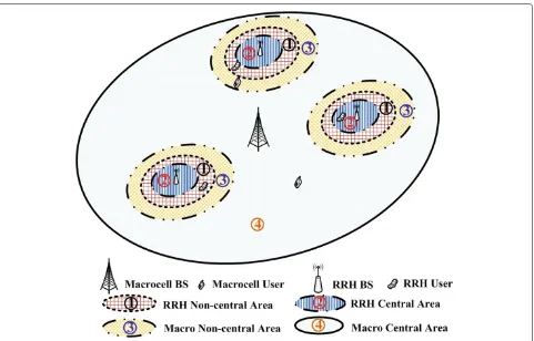
Motivated by the above observations, we propose the following area classification scheme to achieve a good coordination efficiency. The location of each useriis clas-sified into one of four classes according to the relationship between its macrocell RSRP denoted as RSRPmi and its RRH cell RSRP denoted as RSRPri, as shown in Figure 5, whereβdenotes the range expansion bias to increase the offload capacity of the RRH cell [12,13], θ is defined as the RRH cell user coordination bias with θ ≤ β, andα
is defined as the macrocell user coordination bias with
α > β. Correspondingly, four area classes are formulated
as follows and illustrated in Figure 6.
• RRH non-central area. This area is the edge region of the RRH cell. A useri belongs to the RRH non-central area if its RSRPs satisfy the following condition:
RSRPri +θ ≤RSRPmi <RSRPri+β (6)
In Figure 6, it is illustrated as the light red grid area tagged with number 1. A user located in this area usually requires a cooperation between the RRH and the macro BS to suppress the cross-layer
interference. It is easily seen that the estimated minimum value ofθ can be calculated according to the large-scale fading of the channels, given by
θmin=PmdB−(128.1+37.6×log10(Rm)) −(PdBr −(140.7+36.7×log10(Drmin)))
(7)
whereDrmindenotes the minimum distance between the RRH cell user and the RRH BS in km,Rmdenotes
the macrocell service radius in km,PrdBandPmdB denote the transmit power of the RRH node and the macro BS in dB, respectively.
• RRH central area. This area is the interior region of the RRH cell. A useri belongs to the RRH central area if its RSRPs satisfy the following condition:
RSRPmi <RSRPri +θ (8)
In Figure 6, it is illustrated as the pastel striped areas tagged with number 2. A user located in the RRH central area usually does not require a cooperation between the macro BS and the RRH due to the fact that the strength of the interference is much less than that of the effective signal.
• Macro non-central area. This area is the edge region of the macrocell with the RRH cell. A useri belongs to the macrocell non-central area if its RSRPs satisfy the following condition:
RSRPri +β≤RSRPmi <RSRPri +α (9)
In Figure 6, it is illustrated as the orange grid areas tagged with number 3. A user located in this area usually also requires a cooperation between the RRH and the macro BS to suppress the cross-layer
interference. Similarly, the estimated maximum value ofαcan be calculated according to the large-scale fading of the channels, i.e.,
αmax=PmdB−(128.1+37.6×log10(Dmmin))
−(PdBr −(140.7+36.7×log10(Dm_r+Rm)))
20 40 60 80 100 120 140 160 180 200 −90
−80 −70 −60 −50 −40 −30 −20
The distance to the Macro BS (m)
RSRP (dBm)
Macro−cell RSRP RRH−cell RSRP
5dBm
7.2dBm
Figure 2Comparison of macrocell and RRH cell RSRPs.MBS Tx power=46 dBm and RRH Tx power=30 dBm.
155 160 165 170 175 180 185 190
0 10 20 30
The distance between the user and the Macro BS (m)
RCG in Percentage
20 40 60 80 100 120 140 160
0 0.5 1 1.5 2 2.5
The distance between the user and the Macro BS (m)
RCG in Percentage
In the macro cell
In the RRH cell
Figure 3Variation of relative cooperation gain for a user who moves according to the trajectory shown in Figure 4.Nm
Figure 4The trajectory of a user moving from the macrocell center to the RRH cell center.
whereDmmindenotes the minimum distance between the macrocell user and the macro BS in kilometers, andDm_rdenotes the distance between the RRH and
the macro BS in kilometers.
• Macro central area. This area is the interior region of the macrocell. A useri belongs to macrocell central area if its RSRPs satisfy the following condition:
RSRPri +α≤RSRPmi (11)
In Figure 6, it is illustrated as the shaded areas tagged with number 4. Similar to the RRH central area, a user located in this area usually does not require a cooperation between the macro BS and the RRH.
It is worth mentioning that from Theorem 1 in the liter-ature [13], we know that the above-mentioned first three areas are in the shape of an ellipse. Based on the area
classification, the user can request different levels of coor-dination according to its location in different areas, by feeding back different amounts of channel information. By this means, a better trade-off between the coordina-tion gain and the feedback overhead than the convencoordina-tional approach can be achieved.
3.2 Classification criterion
One can see that the parameters{β,θ,α}need to deter-mine in carrying out the above area-specific user classi-fication. Note that the RPB parameterβ can be given by the range expansion mechanism, so it is essential to deter-mine the remaining parameters,θ andα. We propose to determine these two parameters based on the measure of relative cooperation gain. To proceed, assume that a RRH cell useribelongs to the RRH non-central area given by
1
=i: RSRPri+θ ≤RSRPmi <RSRPri +β. (12)
Figure 6The area classification of the heterogenous network based on the RSRP criterion.
If no coordinated beamforming is used, the rate achieved by the user is written as
RθWIC=log2 ⎛ ⎜ ⎝1+
Prαir,r
hri,r H
wri2
σ2+P
mαmi,rE
hmi,r2
⎞ ⎟ ⎠
=log2 ⎛ ⎜ ⎝1+
Prαir,r
hri,rHwri2
σ2+2Nm
t Pmαim,r
⎞ ⎟ ⎠,
(13)
wherewri is the beamforming vector of the RRH for the RRH cell useri. While if a coordinated beamforming strat-egy between the macro BS and the RRH is employed, the user’s achievable rateRθICis calculated as
RθIC=log2 ⎛ ⎜ ⎝1+
Prαri,r
hri,rHwri2
σ2+Pmαm
i,r
hmi,rHwmi,r2 ⎞ ⎟
⎠ (14)
where wmi,r is the beamforming vector of the macro BS which is cooperatively designed such that the caused interferencehmi,rHwmi,r2is minimized. Compared with RθWIC, it achieves a certain gain due to the fact that the cross-layer cross-layer interference is suppressed. To
evaluate the gain, we define the average relative gain for the RRH non-central area as follows:
GR(θ )=E1
Rθ
IC−RθWIC RθWIC
. (15)
It is easy to verify that a smallerθ gives a lower coopera-tion gain due to the fact that the ratio of the interference strength to the effective signal strength decreases withθ decreasing. While on the other hand, a smallerθproduces an enlarged RRH non-central area, resulting in increased cooperation overhead.
To achieve a good trade-off between the cooperation gain and the overhead, we propose to determine the area classification parameterθusing the following criteria:
θ∗=max
θ {θ :GR(θ )≤ξ} (16)
performance loss caused by the non-cooperation of the RRH central area.
Similarly, the other parameterαis determined using the following criteria:
where ζ is a threshold representing the desired relative cooperation gain for the macro user, the set 3denotes the macro non-central area given by
3
=i: RSRPri+β≤RSRPmi <RSRPri +α, (18) RαIC denotes the rate of the macrocell useribelonging to
3
achieved with coordinated beamforming, given by
RαIC =log2
where wmi is the beamforming vector for the macrocell user i, and wri,m is the beamforming vector of the RRH which is cooperatively designed such that the interfer-ence to the macrocell user is minimized.RαWICdenotes the rate achieved by the user without performing coordinated beamforming, calculated as
We note that based on the above criteria (16) and (17), it is still difficult to obtain closed-form solutions of the area classification parameters θ and α. However, pro-vided the detailed coordinated beamforming optimiza-tion approach, the optimal values of θ and α can be achieved via one-dimensional numerical search. In partic-ular, as a practically useful approach,θ andα can both be determined using a deepest slope method. As shown in Section 5.1, GR(θ ) and GM(α) are non-decreasing
and non-increasing functions, respectively, with the slope varying in different intervals. Thus, it is reasonable to chooseθ andα to be the ending points of the sharpest slope interval, such that the coordinated transmission strategy is employed only if it brings significant gain.
4 Area-classified coordinated beamforming based on limited feedback
In order to examine the performance of the proposed area-classified inter-cell interference coordination strat-egy above, as a typical application, in this section, we
develop a coordinated beamforming scheme using area-specific limited feedback. It is known in [15,16] that if coordinated transmission strategy is performed based on a codebook, each user needs to feed back not only the index of the preferred precoding matrix or beamform-ing vector (PMI) and the channel quality indicator (CQI) usually defined as the SINR, but also the index of the com-pany precoding matrix or beamforming vector to be used by the cooperative BS which causes the least interference. With these information, the MBS and the RRH can coop-eratively select a pair of users (also called user pairing, each serves one user) to perform coordinated beamform-ing which imposes minimized interference to each other. To further improve the performance, a cluster-structured codebook is developed by clustering together the code-words with high correlation [31,32]. Based on that, the user feeds back the index of the company cluster instead of the company precoding matrix or beamforming vector. This can significantly improve the success rate of user pairing.
Following the idea of area classification, next we con-sider a cluster-structured codebook-based coordinated beamforming and design an area-specific limited feed-back. To proceed, the MBS codebook Bm and the RRH node codebookBrare defined as follows:
Bm=Bm1,. . .,BmM (21)
and
Br =Br1,. . .,BrN (22)
where Bmi andBri denote theith codeword cluster con-sisting of a set of correlated codewords, in the MBS and the RRH codebooks, respectively. Denote the num-ber of codewords in the clusterBmi andBri asIimandIir, respectively. Then, the total numbers of codewords in the
codebookBm andBr areIm = M i=1
Iim andIr = N i=1
Iir,
respectively. Without loss of generality, we assume that
codeword cluster Bmi consists of the
th codewords in the MBS codebook, and
code-word clusterBri consists of the
codewords in the RRH codebook.
4.1 Area-specific feedback scheme
the RRH central area, it feeds back the area tag, the PMI and the SINR. Otherwise, if it belongs to the non-central area, i.e., the macro central area and the RRH non-central area, it feeds back the company cluster index along with the area tag, the PMI and the SINR. The details are given as follows:
• The RRH central area user determines the preferred codeword and computes the SINR as
PMIri = max
Note that, here, the cross-layer interference is only estimated based on the large-scale fading.
• The RRH non-central area user determines the preferred codeword, the company cluster, and computes the SINR as
PMIri = max
idenotes the company cluster which is
determined as the least interference codeword cluster. To be specific, we select the codeword with the minimum interference on the non-central area RRH user as follows:
Cri = min
j=1,...,Im
hmi,rHwmj , (27)
It also means that this minimum interference codeword should belong toBmPr
i.
• The macro central area user determines the preferred codeword indexPMImi and computesSINRmi using the method similar to that of the RRH central area user.
• The macro non-central area user determines the preferred codeword indexPMImi , the company
cluster indexPim, and the SINR using the method similar to that of the RRH non-central area user.
4.2 Area-classified interference coordination scheme
Based on the above limited feedback method, we develop an area-classified coordinated beamforming scheme sum-marized as Algorithm 1.
Algorithm 1 Area-classified coordinated beamforming
algorithm
1: Area classification:Determine the area classification
parameters α, θ, and β according to the proposed method in Section 3.2, i.e., based on criteria (16) and (17).
2: Area-specific user feedback:Each user carries out
area-specific channel information feedback based on given MBS and RRH codebooks. Then, the MBS and the RRH exchange their served users’ feedback infor-mation through the backhaul.
3: User paring: The MBS and the RRH cooperatively
perform user pairing; a macrocell user and a RRH cell user are paired together if they satisfy one of the following conditions:
I. They are both central area users.
II. They are both non-central area users, and each user’s preferred codeword is included in the company cluster reported by the other user. III. One is a central area user; the other is a
non-central area user. The preferred codeword of the central user is included in the company cluster of the non-central user.
4: User scheduling: Select the best user pair using
the proportional fairness (PF) scheduler, i.e., k∗ =
argmaxk∈K the macrocell user in thekth user pair, respectively; SINRrI(k)(t) and SINRmII(k)(t) denote the SINRs fed back from the users at time slott;R¯rI(k)(t)andR¯mII(k)(t) denote respectively the average rates achieved by the RRH cell user and the macrocell user of the kth user pair, defined as R¯rI(k)(t) = usingtc>1 as the smoothing factor.
5: Coordinated beamforming:The MBS and the RRH
Remark 1.Compared with the conventional codebook-based coordinated beamforming algorithms such as [18,20], the proposed algorithm significantly increases the success rate of user pairinga and thus improves the rate performance. On the other hand, the feedback burden is also reduced by the proposed area-specific feedback method. Note that in the proposed algorithm, central users with non-coordinated transmission may suffer a cer-tain performance loss, but such a loss is controlled to be below the given threshold via the area classification. Therefore, the throughput improvement benefiting from increased user pairing rate usually dominates the overall performance, as verified by the numerical results provided in the following section.
5 Numerical results
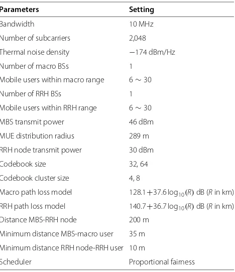
In this section, the performance of the proposed area-classified coordinated beamforming scheme is investi-gated by numerical results. Consider a HetNet consisting of one macro BS and one RRH node, with multiple users uniformly distributed in its coverage. The macro BS and the RRH node are both equipped withM = 4 antennas, and all the users are with a single antenna. For simplicity, in our simulations, we evaluate the coordinated beam-forming on a single carrier of the OFDM system with 10-MHz bandwidth. The channels are generated based on the 3GPP spatial channel model [33]. We assume uniform noise figure in all users, and it is set to be 9 dB. More detailed simulation parameters and assumptions are listed in Table 1. The throughput of each cell is calculated as the sum rate of all its served users averaged on the number of time slots used.
For comparison, two relevant coordinated beamform-ing schemes, i.e., the prioritized selection (PS)-based IC scheme (PS-IC) in [18] and the joint selection-based inter-ference coordination scheme (JS-IC) in [20] are simulated, too. In addition, the performance of the conventional zero-forcing (ZF) coordinated beamforming scheme and the TDMA interference coordination with maximum ratio transmitter (MRT) are simulated, too, both based on limited feedback CSI. Note that for the fairness, the com-paring schemes and the proposed scheme all employ the same codebook, i.e., the cluster-structured discrete fourier transformation (DFT) codebook which is generated in [20].
5.1 Relative cooperation gain performance
It is useful to first investigate the behavior of the newly defined relative cooperation gain, as it is quite relevant to the area classification criterion. In the simulations, we employ codebook-based coordinated beamforming. Figures 7, 8, 9 and 10 show the average relative coopera-tion gain varying with the values ofθandαunder different
Table 1 Simulation parameters
Parameters Setting
Bandwidth 10 MHz
Number of subcarriers 2,048
Thermal noise density −174 dBm/Hz
Number of macro BSs 1
Mobile users within macro range 6∼30
Number of RRH BSs 1
Mobile users within RRH range 6∼30
MBS transmit power 46 dBm
MUE distribution radius 289 m
RRH node transmit power 30 dBm
Codebook size 32, 64
Codebook cluster size 4, 8
Macro path loss model 128.1+37.6 log10(R)dB (Rin km)
RRH path loss model 140.7+36.7 log10(R)dB (Rin km)
Distance MBS-RRH node 200 m
Minimum distance MBS-macro user 35 m
Minimum distance RRH node-RRH user 10 m
Scheduler Proportional fairness
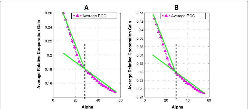
scenarios. The sizes of the codebooks for Figures 7A and 8A and Figures 7B and 8B are 32 and 64, respectively. While in Figures 9 and 10, the size of the codebook is 32. The REBβ is set to 8. The other simulation parameters and assumptions are given in Table 1.
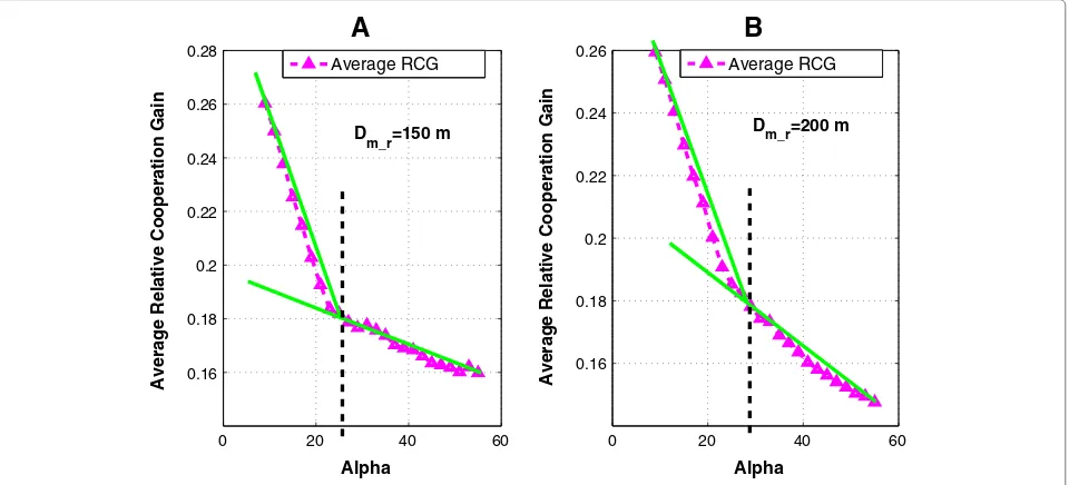
Simulation results show that, in general, the average relative cooperation gain decreases with the value of θ decreasing or with the value ofαincreasing. This is due to the fact that the decreasedθ and the increasedαproduce an enlarged RRH non-central area and macro non-central area, respectively. As a result, the difference between the RSRPs from the macro BS and the RRH node in these non-central areas is increased, which degrades the interference coordination efficiency. This behavior of the average rel-ative gain suggests that expanding the cooperation area cannot always bring significant gain.
−30 −20 −10 0 10 0.58
0.59 0.6 0.61 0.62 0.63 0.64 0.65 0.66 0.67
Theta
Average Relative Cooperation Gain
Average RCG
−20 −10 0 10
0.35 0.36 0.37 0.38 0.39 0.4 0.41 0.42
Theta
Average Relative Cooperation Gain
B
A
Average RCG
Figure 7The behavior ofGR(θ ),Nmt =Ntr=4,Dm_r=200 m.(A)Codebook size is 32.(B)Codebook size is 64.
the right-most slope, i.e., the relative cooperation gain is 0.375 and the value ofθ is−6.
5.2 Throughput performance
The throughput performance of the proposed scheme and the comparing schemes are illustrated in Figures 11, 12 and 13 withξ = 0.375,θ = −6,ζ = 0.18, andα =29, which are determined by the steepest slope method andβ = 8. As shown in Figure 11, in terms of the total throughput of two cells, the proposed scheme significantly outper-forms all other schemes. In particular, compared with the
PS-IC scheme, the ZF scheme and the TDMA scheme, a gain of over 5bit/s/Hz is observed in a wide range. It is also shown that our scheme achieves a better multi-user diversity, and thus, the achieved gain increases with the number of users. Compared with the JS-IC scheme, our scheme exhibits obvious advantage especially when the number of users is small, but the gain shrinks with the number of users increasing. This is due to the fact that the degree of freedom of user pairing is limited by the number of users for the JS-IC scheme, while the proposed area-classified interference coordination scheme improves the
0 20 40 60
0.24 0.26 0.28 0.3 0.32 0.34 0.36 0.38 0.4 0.42 0.44
Alpha
Average Relative Cooperation Gain
B
Average RCG0 20 40 60
0.16 0.18 0.2 0.22 0.24 0.26
Alpha
Average Ralative Cooperation Gain
A
Average RCG
−30 −20 −10 0 10 0.35
0.36 0.37 0.38 0.39 0.4 0.41 0.42 0.43
Theta
Average Relative Cooperation Gain
A
Average RCG−20 −10 0 10
0.35 0.36 0.37 0.38 0.39 0.4 0.41 0.42
Theta
Average Relative Cooperation Gain
B
Average RCGD
m_r=200 m D
m_r=150 m
Figure 9The behavior ofGR(θ ),Nmt =Nrt=4.(A)Dm_r=150 m.(B)Dm_r=200 m.
success rate of user pairing. Similar results are observed in the throughput performance of the macrocell. It is shown in Figure 12 that the proposed scheme also achieves the best performance in terms of macrocell throughput. It is interesting to point out that the performance comparison results are slightly different for the throughput of the RRH cell. As shown in Figure 13, in this metric, the proposed scheme is superior over the PS-IC scheme, the ZF scheme, and the TDMA scheme, but it is slightly poorer than the TDMA scheme. This reveals that the time division inter-ference avoiding scheme usually benefits the small cell of
the HetNet, but its overall achievable throughput of the HetNet is not optimal.
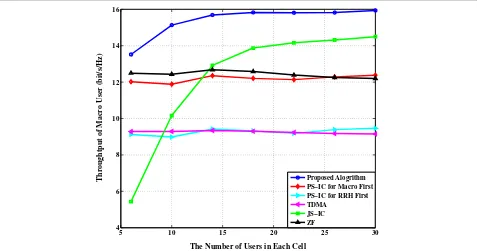
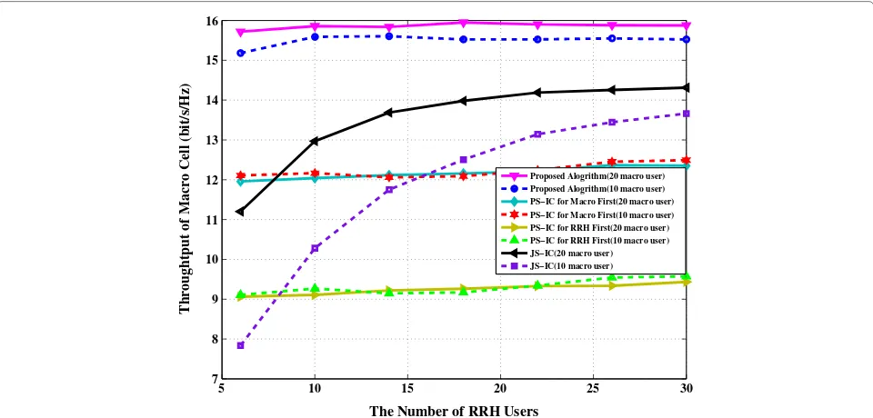
Figure 14 illustrates the macrocell throughput of the proposed scheme and the comparing schemes varying with the number of RRH users, under configurationsξ = 0.375,θ = −6,ζ =0.18,α =29, andβ =8. We consider two macrocell scenarios, i.e., the number of the macrocell users is fixed to be 10 or 20. It can be seen that in our pro-posed scheme, increasing the number of RRH cell users has little impact on the rate performance of the macro-cell, while the macrocell throughput of the JS-IC scheme
0 20 40 60
0.16 0.18 0.2 0.22 0.24 0.26 0.28
Alpha
Average Relative Cooperation Gain
A
Average RCG0 20 40 60
0.16 0.18 0.2 0.22 0.24 0.26
Alpha
Average Relative Cooperation Gain
B
Average RCGD
m_r=150 m
D
m_r=200 m
5 10 15 20 25 30 6
8 10 12 14 16 18 20 22 24 26
The Number of Users in Each Cell
Total Throughput (bit/s/Hz)
Proposed Alogrithm PS−IC for Macro First PS−IC for RRH First TDMA
JS−IC ZF
Figure 11Total throughput performance of the interference coordination schemes,Nm
t =Ntr=4.
suffers a performance loss when the number of RRH users is not large. This is due to the fact that our proposed area-classified interference coordination scheme improves the success rate of user pairing.
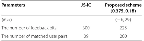
Finally, the feedback overhead of the proposed area-classified IC scheme is evaluated and compared with the
existing JS-IC scheme. The amount of feedback bits and the number of the matched user pairs are calculated for these two schemes. The simulation results are obtained using 1, 000 Monte Carlo runs and are given in Table 2, where the number of users in each cell is configured with 50, and independent channel realizations are generated in
5 10 15 20 25 30
4 6 8 10 12 14 16
The Number of Users in Each Cell
Throughtput of Macro User (bit/s/Hz) Proposed Alogrithm PS−IC for Macro First PS−IC for RRH First TDMA
JS−IC ZF
Figure 12Throughput performance achieved by the macrocell in the interference coordination schemes,Nm
5 10 15 20 25 30 2
3 4 5 6 7 8 9
The Number of Users in Each Cell
Throughtput of RRH User (bit/s/Hz)
Proposed Alogrithm PS−IC for Macro First PS−IC for RRH First TDMA
JS−IC ZF
Figure 13Throughput performance achieved by the RRH cell in the interference coordination schemes,Nmt =Nrt=4.
each run. The size of the codebook is 32. One can see that the proposed scheme saves considerable number of feedback bits and significantly increases the success rate of the user paring. That is why our scheme achieves a much better performance than the existing schemes. In other words, the proposed scheme outperforms the JS-IC scheme in terms of the number of successful user pairs,
i.e., the proposed scheme has more degrees of freedom of user pairing, and has a reduced feedback overhead.
6 Conclusions
In this paper, an area-classified interference coordina-tion strategy was first proposed for heterogeneous cellular networks. The basic principle was to classify the cell
5 10 15 20 25 30
7 8 9 10 11 12 13 14 15 16
The Number of RRH Users
Throughtput of Macro Cell (bit/s/Hz)
Proposed Alogrithm(20 macro user) Proposed Alogrithm(10 macro user) PS−IC for Macro First(20 macro user) PS−IC for Macro First(10 macro user) PS−IC for RRH First(20 macro user) PS−IC for RRH First(10 macro user) JS−IC(20 macro user) JS−IC(10 macro user)
Figure 14Macrocell throughput performance of the interference coordination schemes,Nm
Table 2 Feedback overhead comparison
Parameters JS-IC Proposed scheme
(0.375, 0.18)
(θ,α) (−6, 29)
The number of feedback bits 300 225
The number of matched user pairs 39 260
coverage into different areas and further perform area-specific interference coordination. A new steepest slope method based on relative cooperation gain was provided to realize efficient area classification. Following this idea, an area-classified coordinated beamforming scheme with limited feedback was further proposed for the HetNet. In this scheme, the proposed area-specific limited feed-back scheme could increase the success rate of user pair-ing and thus improve the throughput performance, and with reduced feedback overhead in contrast to existing schemes. The effectiveness of the proposed method was finally verified with simulation results.
Endnote
aIt is seen that in our scheme, two users are paired if
any one of three conditions is satisfied, while in [20], the user pairing succeeds only if condition II is satisfied.
Competing interests
The authors declare that they have no competing interests.
Acknowledgements
This work was supported by the National Science and Technology Major Project of China under Grant 2013ZX03003006-002; National Natural Science Foundation of China under Grants 61271018, 61372101, and 61222102; Research Project of Jiangsu Province under Grants BK20130019, BK2011597, BK2012021, and BE2012167; Open Research Fund of Key Laboratory of Broadband Wireless Communication and Sensor Network Technology, Ministry of Education; and NEC Research Fund.
Author details
1School of Information Science and Engineering, Southeast University,
Nanjing 210096, China.2Key Laboratory of Broadband Wireless
Communication and Sensor Network Technology (Nanjing University of Posts and Telecommunications), Ministry of Education, Nanjing 210003, China.3NEC
Laboratories China, Beijing 100084, China.
Received: 13 May 2013 Accepted: 9 February 2014 Published: 21 February 2014
References
1. V Chandrasekhar, J Andrews, A Gatherer, Femtocell networks: a survey. IEEE Commun. Mag.46(9), 59–67 (2008)
2. M Yavuz, F Meshkati, S Nanda, Interference management and performance analysis of UMTS/HSPA+ femtocells. IEEE Commun. Mag. 47(9), 102–109 (2009)
3. SM Cheng, SY Lien, FS Chu, On exploiting cognitive radio to mitigate interference in macro/femto heterogeneous networks. IEEE Wireless Commun.18(3), 40–47 (2011)
4. A Damnjanovic, J Montojo, Y Wei, T Ji, T Luo, M Vajapeyam, T Yoo, O Song, D Malladi, A survey on 3GPP heterogeneous networks. IEEE Wireless Commun.18(3), 10–21 (2011)
5. D López-Pérez, I Güvenç, G Roche, M Kountouris, T Quek, J Zhang, Enhanced intercell interference coordination challenges in heterogeneous networks. IEEE Wireless Commun.18(3), 22–30 (2011)
6. J Sangiamwong, Y Saito, N Miki, T Abe, S Nagata, Y Okumura, Investigation on cell selection methods associated with inter-cell interference coordination in heterogeneous networks for LTE-advanced downlink, in11th European Wireless Conference 2011 - Sustainable Wireless
Technologies (European Wireless),Vienna, 27–29 April 2011 (IEEE
Piscataway, 2011), pp. 1–6
7. R Madanand, J Borran, A Sampath, N Bhushan, A Khandekar, TF Ji, Cell association and interference coordination in heterogeneous LTE-A cellular networks. IEEE J. Sel. Areas Commun.28(9), 1479–1489 (2010) 8. M Shakir, M Alouini, On the area spectral efficiency improvement of
heterogeneous network by exploiting the integration of macro-femto cellular networks, inIEEE International Conference on Communications
(ICC),Ottawa, 10–15 June 2012 (IEEE Piscataway, 2012), pp. 5695–5700
9. S Mukherjee, Distribution of downlink SINR in heterogeneous cellular networks. Selec. Areas Commun. IEEE J.30(3), 575–585 (2012) 10. P Li, Y Fang, On the throughput capacity of heterogeneous wireless
networks. IEEE Trans. Mob. Comp.11(12), 2073–2086 (2012) 11. M Shirakabe, A Morimoto, N Miki, Performance evaluation of inter-cell
interference coordination and cell range expansion in heterogeneous networks for LTE-Advanced downlink, inInternational Symposium on
Wireless Communication Systems,Aachen, 6–9 Nov 2011 (IEEE Piscataway,
2011), pp. 844–848
12. I Güvenç, M Jeong, I Demirdogen, B Kecicioglu, F Watanabe, Range expansion and inter-cell interference coordination (ICIC) for picocell networks, inIEEE Vehicular Technology Conference (VTC Fall),San Francisco, 5–8 Sept 2011 (IEEE Piscataway, 2011), pp. 1–6
13. D López-Pérez, X Chu, I Güvenç, On the expanded region of picocells in heterogeneous networks. IEEE J. Sel. Sig. Proc.6(3), 281–294 (2012) 14. A Barbieri, A Damnjanovic, T Ji, J Montojo, Y Wei, D Malladi, O Song, G
Horn, LTE femtocells: system design and performance analysis. IEEE J. Sel. Areas Commun.30(3), 586–594 (2012)
15. Y Huang, L Yang, J Liu, A limited feedback SDMA for downlink of multiuser MIMO communication system. EURASIP J. Adv. Signal Process. 2008, 1–13 (2008)
16. Y Du, J Tong, J Zhang, S Liu, Evaluation of PMI feedback schemes for MU-MIMO pairing. IEEE Syst. J.4(4), 505–510 (2010)
17. J Zhang, JG Andrews, Adaptive spatial intercell interference cancellation in multicell wireless networks. IEEE J Sel Areas Commun.28(9), 1455–1468 (2010)
18. J Zhu, H Yang, Interference control with beamforming coordination for two-tier femtocell networks and its performance analysis, inIEEE
International Conference on Communications (ICC),Kyoto, 5–9 June 2011,
(2011), pp. 1–5
19. J Zhu, H Yang, Performance analysis of low-complexity dual-cell random beamforming transmission with user scheduling. EURASIP J. Wireless Commun. Netw.2011, 191 (2011)
20. Y Dai, S Jin, L Jiang, X Gao, M Lei, A PMI feedback scheme for downlink multi-user MIMO based on dual-codebook of LTE-advanced, inIEEE
Vehicular Technology Conference (VTC Fall),Quebec City, 3–6 Sept 2012
(IEEE Piscataway, 2012), pp. 1–5
21. Y Huang, B Rao, An analytical framework for heterogeneous partial feedback design in heterogeneous multicell OFDMA networks. IEEE Trans. Sig. Proc.61(3), 753–769 (2013)
22. Y Huang, B Rao, Performance analysis of heterogeneous feedback design in an OFDMA downlink with partial and imperfect feedback. IEEE Trans. Sig. Proc.61(4), 1033–1046 (2013)
23. M Maso, M Debbah, L Vangelista, Cognitive interference alignment for OFDM two-tiered networks, inInternational Workshop on Signal Processing
Advances in Wireless Communications,Cesme, 17–20 June 2012 (IEEE
Piscataway, 2012), pp. 244–248
24. SK Sharma, S Chatzinotas, B Ottersten, Interference alignment for spectral coexistence of heterogeneous networks. EURASIP J. Wireless Commun. Netw.2013, 46 (2013)
25. Q Li, G Wu, Intracell cooperation and resource allocation in a heterogeneous network with relays. IEEE Trans. Veh. Tech.62(4), 1770–1784 (2013)
27. S He, Y Huang, L Yang, A Nallanathan, P Liu, A Multi-cell beamforming design by uplink-downlink max-min SINR duality. IEEE Trans. Wireless Commun.11(8), 2858–2867 (2012)
28. Y Huang, G Zheng, M Bengtsson, K-K Wong, L Yang, B Ottersten, Distributed multicell beamforming design with limited intercell coordination. IEEE Trans. Sig. Proc.59(2), 728–738 (2011)
29. D Xu, Y Huang, L Yang, Feedback of downlink channel state information based on superimposed coding. IEEE Commun. Lett.11(3), 240–242 (2007)
30. Y Huang, L Yang, M Bengtsson, B Ottersten, Exploiting long-term channel correlation in limited feedback SDMA through channel phase codebook. IEEE Trans Signal Process.59(3), 1217–1228 (2011)
31. 3GPP R1-083759, R1-084141, R1-090051, R1-090777, UE PMI feedback signalling for user pairing coordination. 3GPP TSG RAN WG1 56, (Alcatel-Lucent, 2009) http://www.3gpp.org/ftp/tsg_ran/wg1_rl1/ TSGR1_54b/Docs/. Accessed 16 May 2010
32. 3GPP R1-090926, R1-091307, R1-092031, R1-092546, R1-093333, Best companion reporting for improved single-cell MU-MIMO pairing. 3GPP TSG RAN WG1 56, (Alcatel-Lucent, 2009) http://www.3gpp.org/ftp/tsg_ ran/wg1_rl1/TSGR1_54b/Docs/. Accessed 16 May 2010
33. 3GPP TR25.996 v.8.0.0 Release 8, Spatial channel model for multiple input multiple output (MIMO) simulations. (3GPP Technical report, 2009). http://www.3gpp.org/ftp/tsg_ran/wg1_rl1/TSGR1_54b/Docs/. Accessed 16 May 2010
doi:10.1186/1687-1499-2014-30
Cite this article as:Huanget al.:Area-classified interference coordination for heterogeneous cellular network.EURASIP Journal on Wireless Communications and Networking20142014:30.
Submit your manuscript to a
journal and benefi t from:
7Convenient online submission 7Rigorous peer review
7Immediate publication on acceptance 7Open access: articles freely available online 7High visibility within the fi eld
7Retaining the copyright to your article