Medical Devices: Evidence and Research
Dove
press
M E t h o D o l o g y open access to scientific and medical research
open Access Full text Article
Magnetic localization and orientation of the
capsule endoscope based on a random complex
algorithm
Xiaoqi he1
Zizhao Zheng1,2
Chao hu1
1Ningbo Institute of technology, Zhejiang University, Ningbo, People’s Republic of China; 2taiyuan University of Science and technology, taiyuan, People’s Republic of China
Correspondence: Zizhao Zheng Ningbo Institute of technology, Zhejiang University, Ningbo 315100, People’s Republic of China
tel +86 157 2681 4429, Email [email protected]
Abstract: The development of the capsule endoscope has made possible the examination of the whole gastrointestinal tract without much pain. However, there are still some important problems to be solved, among which, one important problem is the localization of the capsule. Currently, magnetic positioning technology is a suitable method for capsule localization, and this depends on a reliable system and algorithm. In this paper, based on the magnetic dipole model as well as magnetic sensor array, we propose nonlinear optimization algorithms using a random complex algorithm, applied to the optimization calculation for the nonlinear function of the dipole, to determine the three-dimensional position parameters and two-dimensional direction parameters. The stability and the antinoise ability of the algorithm is compared with the Levenberg–Marquart algorithm. The simulation and experiment results show that in terms of the error level of the initial guess of magnet location, the random complex algorithm is more accurate, more stable, and has a higher “denoise” capacity, with a larger range for initial guess values.
Keywords: wireless capsule endoscope, magnet, optimization
Introduction
With the development of science and technology, capsule endoscopy is becoming a preferred method for examination of the gastrointestinal tract, especially for the diag-nosis of intestinal disease.1 The movement of the capsule in the gastrointestinal tract of
human body depends on gastrointestinal peristalsis, so it is important for the doctor to acquire precise positioning information of the capsule to observe some specific areas of the tissues. Currently, a widely used positioning technique is the magnetic method, which detects the change of the magnetic intensity generated by a magnet attached to the capsule. The magnet signal are changes as a function of the static magnetic field and is not affected by the human body, so this positioning method can obtain high positioning accuracy. Also, it can directly determine the parameters for the position and direction of the capsule, for real-time location tracking. Based on the model of magnetic field positioning, researchers have proposed many positioning methods for the localization and orientation of the magnet.2–11 For instance, Golden and Silverstein have developed
a medical tube that can be positioned in the body of patients. This medical tube can be located by a detection instrument, based on the magnetic intensity generated by the magnets inside the tube. The detection instrument moves around the body until the maximum magnetic intensity is detected, and then, the position of the magnet is calcu-lated. However, this method cannot determine the direction of the magnet and has no real-time tracking system.2 Prakash and Spelman proposed a method for localizing a
single magnetic dipole has been implemented in vitro using a magnetic marker. This uses
Medical Devices: Evidence and Research downloaded from https://www.dovepress.com/ by 118.70.13.36 on 24-Aug-2020
For personal use only.
Number of times this article has been viewed
This article was published in the following Dove Press journal: Medical Devices: Evidence and Research
Dovepress
he et al
an eight fluxgate magnetic sensor to measure the magnetic intensity of the magnetic marker, where the Newton algorithm is applied as the positioning algorithm to calculate the position and direction of the target, but the positioning precision of this method is not very high.3 Yang et al used swarm
intel-ligence algorithms, including genetic algorithms and particle swarm algorithms, to optimize the function of the magnetic positioning model. Their results showed that particle swarm optimization was more accurate to meet the requirement of localization. But for real-time tracking of the magnet, the algorithm is complex, and the speed of the algorithm did not meet the requirement for localization.7 Hu et al put forward a
new localization algorithm. First, they used an improved linear algorithm to obtain the localization parameters, by finding the eigenvector corresponding to the minimum eigenvalue of the objective matrix. Then, these parameters were used as the initial guess values for the positioning parameters of a nonlinear location algorithm so that the algorithm had better robustness and more precise positioning results.10
To find a more efficient algorithm, a hybrid algorithm combining different algorithms might be a suitable method to meet the need for high positioning precision and fast speed. Based on the magnetic dipole model, some nonlinear local-ization methods have been tested, such as Powell’s, Downhill Simplex, DIRECT, multilevel coordinate search, and the Levenberg–Marquardt (LM) algorithm. Hu et al concluded that the LM algorithm is better than other nonlinear algorithms.12
However, the LM algorithm easily gets into local optimality, so when the positioning range becomes larger, it has insuffi-cient stability and antinoise ability. Therefore, we tested some hybrid methods and obtained better results. In this paper, we put forward a new nonlinear positioning algorithm based on the random complex method. In terms of accuracy and stabil-ity, for the three-dimensional position parameters and two-dimensional direction optimization calculation, the random complex algorithm (RCA) is superior to the LM algorithm and other algorithms because of its greater error level of the initial guess of magnet location and “denoising” capacity.
The organization of this paper is as follows: In the fol-lowing section, we present a magnetic positioning system for the capsule endoscope. After this, we present the nonlinear magnetic positioning algorithm. Then, we present the perfor-mance and evaluation, followed by our conclusions.
Magnetic positioning structure
of the capsule endoscope
As shown in Figure 1, the capsule endoscope has an enclosed thin, annular magnetic tube that builds the
Battery Magnet
Antena Radio
transmitter Imager
Lens LEDs
Optical dome
Figure 1 Capsule endoscope with magnetic tube. Abbreviation: lED, light-emitting diode.
Sensor array
GI tract Capsule
Magnet
N S
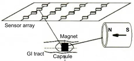
Figure 2 Axially magnetized magnetic sets. Abbreviation: gI, gastrointestinal.
magnetic field and which does not take up very much of the internal space.12
To detect the capsule endoscope in the body, a mag-netic sensor array (Figure 2), which is situated outside of the human body, is designed to measure the magnetic field strength generated by the magnetic tube as the capsule moves inside the human body.
Obviously, the signal received by the magnetic field sen-sor array is related to the magnet tube position and direction with respect to the sensors. After sampling the sensor data, the position and direction parameters of the tube can be computed by the corresponding algorithm.
Nonlinear magnetic
positioning algorithm
Model description
When a capsule moves in the gastrointestinal tract of human body, the position and direction of the capsule change. Therefore, we define a fixed coordinate system (as shown in Figure 3), and under the coordinate system, the magnet’s position is represented by (a,b,c)T, and the magnet orientation is represented by H0= (m,n,p)T.
Assume that there are N sensors, with lth sensor located at (xl,yl,zl)T (serial number l, l=1, 2, …, N). We denote three unit coordinate vectors as i, j, and k corresponding to the axes
Medical Devices: Evidence and Research downloaded from https://www.dovepress.com/ by 118.70.13.36 on 24-Aug-2020
Dovepress localization and orientation of the capsule endoscope by RCA
x, y, and z respectively. The magnetic flux density at the lth
sensor location can be represented by:
B B i B j B k M H P P
R
H R
B H
l lx ly lz
r T l l
l l T = + + = ⋅ − = µ µ π 0 0 5 0 3 0 4 3 3 ( ) ( ⋅⋅ − = P P R H
R l N
l l l l ) ( , , , ), 5 0
3 1 2… (1)
where Blx, Bly, and Blz are the three orthogonal components of
Bl; N is the total number of sensors; µr is the relative perme-ability (µr≈ 1 in the air); µ0 is the vacuum permeability (µ0=
4π×10–7T ⋅ m/A); M
T is the constant (related to the volume and intensity of magnetization) that characterizes the magnetic field intensity of magnets; the vectors Pl connecting the lth sensor and the magnet can be represented by (xl – a,yl – b,zl – c)T; and R
l is
the module of Pl, namely, Rl = (xl−a)2+(yl−b)2+(zl−c)2
. The H0 vector is characterizing the direction of the magnetic field of magnets, and we can add the constraints:
m2+ n2+ p2= 1 (2)
Expanding Equation 1, we have:
B B m x a n y b p z c x a
R
m R
lx T
l l l l
l l = − + − + − ⋅ − − 3 5 3 [ ( ) ( ) ( )] ( ) (3)
B B m x a n y b p z c y b
R
n R
ly T
l l l l
l l = − + − + − ⋅ − − 3 5 3 [ ( ) ( ) ( )] ( ) (4)
B B m x a n y b p z c z c
R
p R
lz T
l l l l
l l = − + − + − ⋅ − − 3 5 3 [ ( ) ( ) ( )] ( ) (5)
If we detect Blx, Bly, and Blz (l $ 2), by using Equations 2–5, the location parameter (a,b,c)T and direction parameter (m,n,p)T can be determined.
According to the magnetic positioning model, there are five unknown parameters that must be solved, and the num-ber of sensors needs to be N $2. But due to the presence of noise, the solution is not unique. We define a target error function (E) as follows:
E = Ex+ Ey+ Ez, (6)
for which
E B BT m x a n y b p z c x a
R
m R
x lx l l l l
l l = − − + − + − ⋅ − −
3 5 3
[ ( ) ( ) ( )] ( ) =
∑
2 1 l N , (7)E B B m x a n y b p z c y b
R
n R
y ly T l l l l
l l = − − + − + − ⋅ − −
3 5 3
[ ( ) ( ) ( )] ( ) =
∑
l1 2N
,
(8) and
E B B m x a n y b p z c z c
R
p R
z lz T l l l l
l l = − − + − + − ⋅ − −
3 5 3
[ ( ) ( ) ( )] ( ) =
∑
2 1 l N . (9)This is a nonlinear least squares problem, so the position-ing problem becomes a nonlinear optimization problem. We find (a,b,c)T and (m,n,p)T to get the minimum error of the target through the optimization algorithm, namely:
a b c m n pEx Ey Ez
s t m n p
, , , , , arg min . . . + + + + =
2 2 2 1 (10)
In order to measure the effectiveness of the algorithm, positioning and orientation errors are defined as:
Ep= (as−at)2+(bs−bt)2+(cs−ct)2 (11)
and
Eo= (ms−mt)2+(ns−nt)2+(ps−pt) ,2 (12)
where (at bt ct mt nt pt) and (as bs cs ms ns ps) represent the setting and calculated parameters of the position and orientation.
X
0 Y
(X1,Y1,Z1) R1 (a,b,c)
Z
H0
Figure 3 Axial circular magnet (magnetic dipole) model.
Notes: (a, b, c) is the magnet position; (X1, y1, Z1) is a spatial point; h0 is the
normalized vector; R1 is the distance between the magnet and the spatial point.
Medical Devices: Evidence and Research downloaded from https://www.dovepress.com/ by 118.70.13.36 on 24-Aug-2020
Dovepress
he et al
Random complex algorithm
For the localization of the capsule endoscope, the accuracy and execution time are very important, and the nonlinear algorithm should be of high speed and precision. There are some widely used nonlinear algorithms, such as Powell’s, downhill, simplex, DIRECT, multilevel coordinate search, and the LM algorithm. We tried these algorithms and found some defects with the efficiency, so a nonlinear optimization algorithm, RCA, is introduced.
RCA was proposed by Andersson on the basis of the complex method.13 In this method, the complex is constituted
in the constrained space; then the function values of the complex vertices are compared one by one so that the worst vertex will be replaced by a new vertex whose function values are improved and satisfy the constraints. Repeating this pro-cess, the result gradually approaches the most accurate one.
The step of computing the optimization of RCA is described in Figure 4.
Performance evaluation
In a real system, there will be noise due to the influences of the human body and the environmental factors. So the non-linear optimization algorithms were tested for their ability to denoise and with the initial setting range of the positioning parameters. In this section, we compare RCA with the LM algorithm in terms of positioning error, direction error, and the execution time of the algorithm. Also, the effects of initial setting errors are used to test the stability of each RCA and LM algorithm.
Although it requires at least five sensors to solve a function for the five unknown positioning and orientation parameters, the greater the number of sensors, the higher is the positioning
and
(16) The random complex algorithm
Assume that the discussed issue is described as:
Step 1 Randomly generate k vertices in the feasible region and set Genmax
(the maximum number of iterations)
Step 2 Determining the termination criterion.
If the number of iterations output
stop;
otherwise, do Step 3
Step 3 Obtain function values and coordinates of the best point and the worst point,
and calculate the centroid point.
Obtain function values of k vertices and order these from small to large so as to
obtain the best point, and the worst point, and calculate the centroid point
(15)
gen gen> max
(14) (13)
Figure 4 (Continued)
Medical Devices: Evidence and Research downloaded from https://www.dovepress.com/ by 118.70.13.36 on 24-Aug-2020
Dovepress localization and orientation of the capsule endoscope by RCA
–0.2 –0.1
0 0.1
0.2
–0.2 –0.1 0 0.1 0.20 0.05 0.1 0.15 0.2
X (mm) Y (mm)
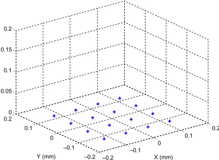
Figure 5 Arrangement of sensors. Figure 4 the calculation steps for the random complex algorithm (RCA).
Calculate the centroid point according to formula (16) and obtain the function value
(17)
Generally,
If , replaces of
If , replaces of
If , do Step 5; if , do Step 6
Step 5 The contraction phase
When the number of iterations is less than the maximum number of iterations, the reflection point is improved with the formula:
(18) where represents the contractive cycles when the
contractive point as the worst point,
[0,1].
If , replaces of
If , replaces of
Step 6 Coordinate and the function value of the worst point are replaced by the
newly obtained point
Return to Step 2
Step 4 Obtain the coordinate and function value of reflection point and for comparison with that of the worst point.
=1.2 (αis the reflection coefficient) α
gen = gen + 1
,
is a constant), R is a random number in (
accuracy. The simulation is based on the layout for 16 three-dimensional magnetic sensors evenly arranged on the 240 ×
240 mm square area X-Y plane, as shown in Figure 5.9
In the simulation, the RCA and the LM algorithms are compared for algorithm characteristics, based on the nonlin-ear magnetic positioning model.
tolerance of the initial guess of the
parameters and stability of the algorithm
The nonlinear optimization algorithms usually require an initial guess of the parameters, or their bounds, to search for the optimal value. If the initial parameters (or bounds) are chosen with large error, the algorithms may fail to give the
Medical Devices: Evidence and Research downloaded from https://www.dovepress.com/ by 118.70.13.36 on 24-Aug-2020
Dovepress
he et al
correct (global optimization) solution because there might be many local optima. Therefore, the chosen optimization algorithm should have large tolerance for the initial guess of the parameters.
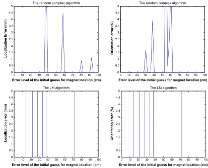
For all the test vectors, the vector Vr = [–0.05, –0.00, 0.97, 0.00, –1.00, 0.00] is the most representative when the error levels of the initial location guess is 100 cm. The simulation results of RCA and the LM algorithm are shown in Figure 6.
For Figure 6, we observe that if the location error is 5 mm and direction error is 5%, the LM algorithm lapses when the initial guess of location is 15 cm, and RCA lapses when the initial guess of location is 36 cm.
For all the 32 test vectors, when the initial guess of locali-zation is in the range of 10–100 cm, if the location error is 5 mm and direction error is 5%, the simulation results of the proportion of successful points of the RCA and the LM algorithm are shown in Figure 7.
The simulation results show that when the limit for the initial guess of localization is 10 cm for the RCA and the LM
algorithm, all test points are successful. But when the limit for the initial guess of localization is extended to 30 cm, 37.5% of test points of the LM algorithm lapse, while the RCA can still successfully and accurately calculate the optimal position and direction. So the tolerance of the initial guess for RCA is higher than that for the LM algorithm. In Figure 9, with the increase in error level of the initial guess for magnet location, the proportion of successful points in the RCA and the LM algorithm will decrease, but the RCA is better than the LM algorithm. Thus, the stability of the RCA is better than that of the LM algorithm.
Denoise capacity
The algorithm and system implementation should be robust with regard to the noise in the sensor data. In a practical sys-tem, there is always some noise due to the influences of the human body and the environment. In this section, we present the simulation results for the denoising ability of the LM algorithm and RCA, and the results obtained by a real sensor array system with sixteen three-axis Hall effect sensor.
0 10 20 30 40 50 60 70 80 90 100 0
0.5 1 1.5 2 2.5 3 3.5 4 4.5
5 The random complex algorithm
Error level of the initial guess for magnet location (cm)
Localization Error (mm)
0 10 20 30 40 50 60 70 80 90 100 0
0.5 1 1.5 2 2.5 3 3.5 4 4.5
5 The random complex algorithm
Error level of the initial guess for magnet location (cm)
Orientation error (%)
0 10 20 30 40 50 60 70 80 90 100 0
0.5 1 1.5 2 2.5 3 3.5 4 4.5
5 The LM algorithm
Error level of the initial guess for magnet location (cm)
Localization error (mm)
0 10 20 30 40 50 60 70 80 90 100 0
0.5 1 1.5 2 2.5 3 3.5 4 4.5
5 The LM algorithm
Error level of the initial guess for magnet location (cm)
Orientation error (%)
Figure 6 Position and orientation errors for the error levels of the initial guess of location. Abbreviation: lM, levenberg–Marquart.
Medical Devices: Evidence and Research downloaded from https://www.dovepress.com/ by 118.70.13.36 on 24-Aug-2020
Dovepress localization and orientation of the capsule endoscope by RCA
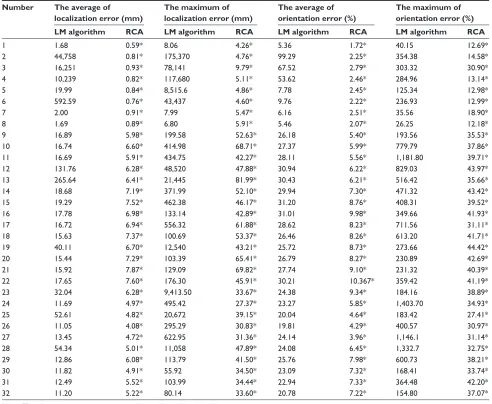
Table 1 the average and maximum of localization and orientation errors
Number The average of localization error (mm)
The maximum of localization error (mm)
The average of orientation error (%)
The maximum of orientation error (%) LM algorithm RCA LM algorithm RCA LM algorithm RCA LM algorithm RCA
1 1.68 0.59* 8.06 4.26* 5.36 1.72* 40.15 12.69*
2 44,758 0.81* 175,370 4.76* 99.29 2.25* 354.38 14.58*
3 16,251 0.93* 78,141 9.79* 67.52 2.79* 303.32 30.90*
4 10,239 0.82* 117,680 5.11* 53.62 2.46* 284.96 13.14*
5 19.99 0.84* 8,515.6 4.86* 7.78 2.45* 125.34 12.98*
6 592.59 0.76* 43,437 4.60* 9.76 2.22* 236.93 12.99*
7 2.00 0.91* 7.99 5.47* 6.16 2.51* 35.56 18.90*
8 1.69 0.89* 6.80 5.91* 5.46 2.07* 26.25 12.18*
9 16.89 5.98* 199.58 52.63* 26.18 5.40* 193.56 35.53*
10 16.74 6.60* 414.98 68.71* 27.37 5.99* 779.79 37.86*
11 16.69 5.91* 434.75 42.27* 28.11 5.56* 1,181.80 39.71*
12 131.76 6.28* 48,520 47.88* 30.94 6.22* 829.03 43.97*
13 265.64 6.41* 21,445 81.99* 30.43 6.21* 516.42 35.66*
14 18.68 7.19* 371.99 52.10* 29.94 7.30* 471.32 43.42*
15 19.29 7.52* 462.38 46.17* 31.20 8.76* 408.31 39.52*
16 17.78 6.98* 133.14 42.89* 31.01 9.98* 349.66 41.93*
17 16.72 6.94* 556.32 61.88* 28.62 8.23* 711.56 31.11*
18 15.63 7.37* 100.69 53.37* 26.46 8.26* 613.20 41.71*
19 40.11 6.70* 12,540 43.21* 25.72 8.73* 273.66 44.42*
20 15.44 7.29* 103.39 65.41* 26.79 8.27* 230.89 42.69*
21 15.92 7.87* 129.09 69.82* 27.74 9.10* 231.32 40.39*
22 17.65 7.60* 176.30 45.91* 30.21 10.367* 359.42 41.19*
23 32.04 6.28* 9,413.50 33.67* 24.38 9.34* 184.16 38.89*
24 11.69 4.97* 495.42 27.37* 23.27 5.85* 1,403.70 34.93*
25 52.61 4.82* 20,672 39.15* 20.04 4.64* 183.42 27.41*
26 11.05 4.08* 295.29 30.83* 19.81 4.29* 400.57 30.97*
27 13.45 4.72* 622.95 31.36* 24.14 3.96* 1,146.1 31.14*
28 54.34 5.01* 11,058 47.89* 24.08 6.45* 1,332.7 32.75*
29 12.86 6.08* 113.79 41.50* 25.76 7.98* 600.73 38.21*
30 11.82 4.91* 55.92 34.50* 23.09 7.32* 168.41 33.74*
31 12.49 5.52* 103.99 34.44* 22.94 7.33* 364.48 42.20*
32 11.20 5.22* 80.14 33.60* 20.78 7.22* 154.80 37.07*
Note: the values with asterisks represent the better values of two algorithms. Abbreviations: RCA, random complex algorithm; lM, levenberg–Marquart.
0 10 20 30 40 50 60 70 80 90 100
0 0.2 0.4 0.6 0.8 1 1.2 1.4 1.6 1.8 2
Error level of initial guess for magnet location (cm)
Percentage of the effective points (%)
RCA
Levenberg–Marquardt
Figure 7 Proportion of effective points for the different initial errors of position. Abbreviation: RCA, random complex algorithm.
For all the 32 test vectors, when the initial guess of locali-zation is 10 cm, under different noise levels (0.1–1,000, where 1,000 is approximately 40% full sensing range) of random noises, the average and maximum localization and orientation errors of the LM algorithm and RCA are shown in Table 1.
According to Table 1, when the noise level is from 0.1 to 1,000, the RCA has smaller fluctuation, and the average value of localization and orientation error of the RCA is smaller than that of the LM algorithm.
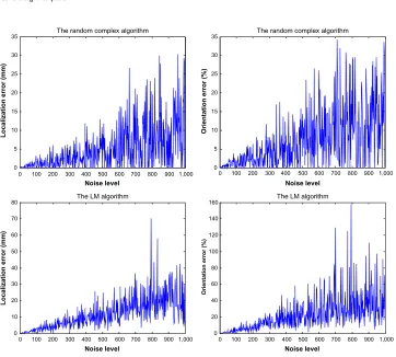
For the real vectors Vr1=[0.0853, –0.0956, 0.0520, 0.9183, 0.3958, 0.0000] and Vr2=[–0.815, 0.070, 0.097, 0.2169, 0.9762, 0.0000], when the initial guess of localization is 10 cm and the noise level, dl, is in the range of 0 to 1,000, the simulation results of the RCA and the LM algorithm are shown in Figures 8 and 9.
Medical Devices: Evidence and Research downloaded from https://www.dovepress.com/ by 118.70.13.36 on 24-Aug-2020
Dovepress
he et al
0 100 200 300 400 500 600 700 800 900 1,000 0
0.5 1 1.5 2 2.5 3 3.5 4
4.5 The random complex algorithm
Noise level
Localization error (mm)
0 100 200 300 400 500 600 700 800 900 1,000 0
2 4 6 8 10 12
14 The random complex algorithm
Noise level
Orientation error (%)
0 100 200 300 400 500 600 700 800 900 1,000 0
1 2 3 4 5 6×10
4 The LM algorithm
Noise level
Localization error (mm)
0 100 200 300 400 500 600 700 800 900 1,000 0
50 100 150 200 250
300 The LM algorithm
Noise level
Orientation error (%)
Figure 8 Position and orientation errors via noise level; vector Vr1. Abbreviation: lM, levenberg–Marquart.
0 100 200 300 400 500 600 700 800 900 1,000 0
5 10 15 20 25 30
35 The random complex algorithm
Noise level
Localization error (mm)
0 100 200 300 400 500 600 700 800 900 1,000 0
5 10 15 20 25 30
35 The random complex algorithm
Noise level
Orientation error (%)
0 100 200 300 400 500 600 700 800 900 1,000 0
10 20 30 40 50 60 70
80 The LM algorithm
Noise level
Localization error (mm)
0 100 200 300 400 500 600 700 800 900 1,000 0
20 40 60 80 100 120 140
160 The LM algorithm
Noise level
Orientation error (%)
Figure 9 Position and orientation errors via noise level; vector Vr2. Abbreviation: lM, levenberg–Marquart.
Medical Devices: Evidence and Research downloaded from https://www.dovepress.com/ by 118.70.13.36 on 24-Aug-2020
Dovepress localization and orientation of the capsule endoscope by RCA
0 5 10 15 20 25 30 0
2 4 6 8 10 12 14 16 18 20
Sample number
Orientation error (%
)
RCA
Levenberg-Marquardt RCAmeanO LMmeanO
0 5 10 15 20 25 30
0 2 4 6 8 10 12 14 16 18 20
Sample number
Localization error (mm)
RCA
Levenberg-Marquardt RCAmeanP LMmeanP
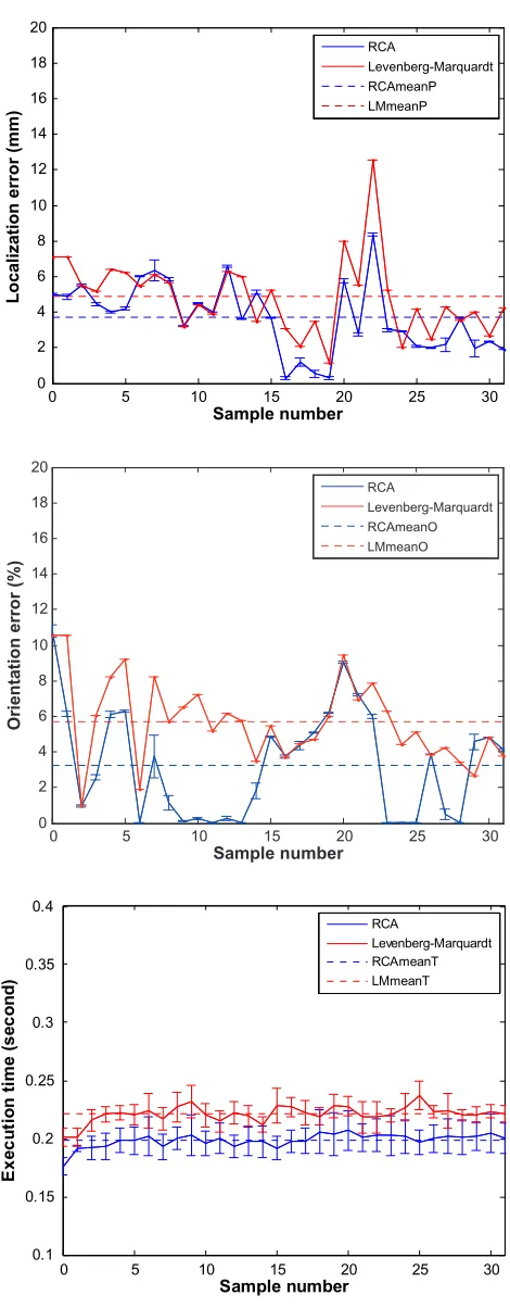
Figure 10 Comparison for the position and direction error and execution time of real data.
Abbreviations: lMmeanP, the average value of position error of lM algorithm; RCAmeanP, the average value of position error of RCA algorithm; lMmeano, (the average value of direction error of lM algorithm; RCAmeano, the average value of direction error of RCA algorithm; lMmeant, the average value of execution time of lM algorithm; RCAmeant, the average value of execution time of RCA algorithm; RCA, random complex algorithm.
From the simulation results, the average of the position error for the RCA is 0.76 mm, and the maximum value is 4.60 mm; the mean value of the orientation error is 2.22%, and the maximum value is 12.99%. The average of the posi-tion error for the LM algorithm is 592.59 mm, and the maxi-mum value is 4.34×104 mm; the mean value of the orientation
error is 9.75%, and the maximum value is 236.93%. From the simulation results, the average of the posi-tion error for RCA is 4.91 mm, and the maximum value is 34.50 mm; the mean value of the orientation error is 7.32%, and the maximum value is 33.74%. The average of the posi-tion error for the LM algorithm is 11.82 mm, and the maxi-mum value is 55.92 mm; the mean value of the orientation error is 23.09%, and the maximum value is 168.41%.
From the above figure, when the noise level dl ranges from 0 to 1,000, the condition of failure may occur for the LM algorithm but does not happen for the RCA; comparing with the LM algorithm, the noise immunity of the RCA is stronger.
Real experiment and comparison
with testing results
We built an actual experimental system, which consists of magnetic sensors, amplifiers, an analog-to-digital (A/D) con-verter, and a computer. The 16 magnetic sensors (Figure 7) are made of three-axis Hall sensors. In the system, the magnetic sensors receive the magnetic signals and convert them to electrical signals. The amplifiers amplify (or adjust) the signal magnitude until suitable to the range for A/D conversion. Then, the computer selects the particular signal channel and samples the signal using a 12-bit A/D converter (we tried a 16-channel, ISA bus data acquisition card [PCL-818L; Advantech Co, Ltd, Taipei, Taiwan]). In the experimental process, 32 positions of magnet are selected and the cor-responding data of magnetic induction intensities in each position is obtained. Based on the data, the RCA compares with the LM algorithm in terms of the position and direction error, and the execution time of the algorithm, and the result is shown in Figure 10.
In Figure 10, in each position among 32 positions, when the algorithms (RCA and LM) were run, we obtained the aver-age values for positioning and direction errors and the run-ning time of the algorithms, with error bars (95% confidence interval) for all of the mean values. The error bars specify the size of the uncertainty of the measurement data. For the LM algorithm, the position error is less than 12.51 mm, and the average value is 4.86 mm; the direction error is less than 10.56%, and the average value is 5.71%; and the execution
0 5 10 15 20 25 30
0.1 0.15 0.2 0.25 0.3 0.35 0.4
Sample number
E
xe
cu
ti
on
t
im
e
(s
ec
on
d)
RCA
Levenberg-Marquardt RCAmeanT LMmeanT
Medical Devices: Evidence and Research downloaded from https://www.dovepress.com/ by 118.70.13.36 on 24-Aug-2020
Medical Devices: Evidence and Research
Publish your work in this journal
Submit your manuscript here: http://www.dovepress.com/medical-devices-evidence-and-research-journal Medical Devices: Evidence and Research is an international,
peer-reviewed, open access journal that focuses on the evidence, technology, research, and expert opinion supporting the use and application of medical devices in the diagnosis, treatment and management of clini-cal conditions and physiologiclini-cal processes. The identification of novel
devices and optimal use of existing devices which will lead to improved clinical outcomes and more effective patient management and safety is a key feature. The manuscript management system is completely online and includes a quick and fair peer-review system. Visit http://www. dovepress.com/testimonials.php to read real quotes from authors.
Dovepress
Dove
press
he et al
time of the algorithm is less than 0.24 seconds, and the average value is 0.22 seconds. Alternately, for the RCA, the position error is less than 8.34 mm, and the average value is 3.70 mm; the direction error is less than 10.80%, and the aver-age value is 3.27%; and the execution time of the algorithm is less than 0.21seconds, and the average value is 0.20 seconds. Obviously, for the 32 positions in the actual measured data, the RCA performs better than the LM algorithm for the posi-tion, the direcposi-tion, and the execution time.
Summary
As mentioned above, the positioning and tracking technology of the capsule is the key technology for capsule endoscopy. To realize stable and accurate localization, we must find appropriate algorithms. Based on the magnetic positioning model of the capsule endoscope with an embedded permanent magnet, we propose a new localization algorithm – the RCA. Simulation results show that the RCA is better than the LM algorithm with regard to the stability, the initial guess setting range, and noise immunity. We have tested and compared actual experimental data, based on an actual test system, and find that the RCA is better than the LM algorithm with regard to the position accuracy and the execution time of the algorithm. For the actual localization system, we can design a hybrid algorithm combining the RCA nonlinear algorithm with other algorithms, by first using other algorithms to find a initial position of the capsule and then using the RCA to track it in a real system.
Acknowledgments
This work was supported by the National Natural Science Foundation of China (grant number 61273332) and Ningbo Science and Technology (Innovation Team) plan project (grant number 2014B82015).
Disclosure
The authors report no conflicts of interest in this work.
References
1. Iddan G, Meron G, Glukhovsky A, Swain P. Wireless capsule endoscopy. Nature. 2000;405(6785):417.
2. Golden RN, Silverstein FE, inventors. Apparatus and method for locat-ing a medical tube in the body of a patient. United States patent US 19975622169. April 22, 1997.
3. Prakash NM, Spelman FA. Localization of a magnetic marker for GI motility studies: an in vitro feasibility study. Presented at: Engineering in Medicine and Biology Society, 1997: Proceedings of the 19th Annual International Conference of the IEEE; October 30–November 2;1997; Chicago, IL.
4. Hu C. Localization and Orientation System for Robotic Wireless Capsule Endoscope [dissertation]. Edmonton: University of Alberta; 2006.
5. Liu L, Liu W, Hu C, Meng MQH. Hybrid magnetic and vision localiza-tion technique of capsule endoscope for 3D recovery of pathological tissues. Presented at: IEEE 9th World Congress on Intelligent Control and Automation (WCICA); June 21–25; 2011; Taipei.
6. Wang K, Yan G, Jiang P, He W, Guo X. [Localization system for electrical capsule based on permanent magnetic field]. Sheng Wu Yi Xue Gong Cheng Xue Za Zhi. 2007;24(5):1148–1151. Chinese. 7. Yang W, Hu C, Meng MQH, Song S, Dai H. A six-dimensional magnetic
localization algorithm for a rectangular magnet objective based on a particle swarm optimizer. IEEE Trans Magn. 2009;45(8):3092–3099. 8. Popek KM, Mahoney AW, Abbott JJ. Localization method for a
magnetic capsule endoscope propelled by a rotating magnetic dipole field. Presented at: IEEE International Conference on Robotics and Automation (ICRA); May 6–10, 2013; Karlsruhe.
9. Hu C, -H Meng M, Mandal M. Efficient linear algorithm for magnetic localization and orientation in capsule endoscopy. Conf Proc IEEE Eng Med Biol Soc. 2005;7:7143–7146.
10. Hu C, Yang W, Chen D, Meng MQ, Dai H. An improved magnetic localization and orientation algorithm for wireless capsule endoscope. Conf Proc IEEE Eng Med Biol Soc. 2008;2008:2055–2058.
11. Hu C, Li M, Meng MH, Song S. A new tracking system for three magnetic objectives. IEEE Trans Magn. 2010;46(12):4023–4029. 12. Hu C, Meng MH, Mandal M. Efficient magnetic localization and
orientation technique for capsule endoscopy. International Journal of Information Acquisition. 2005;2(01):23–36.
13. Andersson J. Multiobjective Optimization in Engineering Design Appli-cations to Fluid Power Systems [dissertation]. Linköping: Linköping University; 2001.
Medical Devices: Evidence and Research downloaded from https://www.dovepress.com/ by 118.70.13.36 on 24-Aug-2020