Themed Section : Engineering and Technology
Seismic Analysis of Irregular RC Structure with Cross-Bracing
System
Rohan Chavan1, Prachi Sohoni2
1M.Tech Structure, Walchand College of Engineering, Sangli , Maharashtra, India
2Assistant Professor, Department of Applied Mechanics, Walchand College of Engineering, Sangli, Maharashtra,
India
ABSTRACT
Steel bracing system is one of the most suitable methods for improvement of reinforced concrete structures against lateral loading. Bracing systems is very efficient in reducing lateral displacements by increasing stiffness and strength. In proposed problem G+11 story irregular RC buildings are analysed with and without cross bracing system, which is one of the best of concentric bracing systems. Non-linear time history analysis is carried out in order to find out response of structure for various ground motions. ETABS 2016 software is used for analysis purpose. The performance of the building is evaluated in terms of story drifts, lateral displacements, bending moments, axial forces and base shear.
Keywords: Irregularity, Bracing Systems, Maximum Story Displacement, Story Drift, Time History Analysis.
I.
INTRODUCTIONThe primary design of structural systems used in building is to transfer gravity loads. Besides these vertical loads, buildings are also subjected to lateral loads caused by earthquake, wind, blasts etc. Hence the major concern in the design of the multi-storey buildings is to have enough lateral stability of the structure to resist lateral forces and to control the lateral drift. Currently, there are many structural systems such as rigid frame, braced frame and shear-walled frame, frame-tube, braced-tube, bundled-tube and outrigger systems that can be used to enhance the lateral resistance in tall buildings.
In many cases laterally braced systems make a building stiffer against horizontal forces, and thus minimize the amount of relative lateral movement and consequently the damage. It is seen that both structural and non-structural damages are observed during earthquake ground motions are primarily produced by lateral displacements. Therefore, in
order to increase the seismic strength of framed structures, steel bracing or shear walls are often used. However, considering the ease of construction and the relatively low cost, steel bracing appears to be a better alternative. Steel bracings can be arranged like diagonal, cross bracing or X, V, inverted V or Chevron. In this study, irregular reinforced concrete buildings are analysed with cross bracing system, which is one of the effective bracing types.
A. Proposed Work
The main purpose is to find effect of bracing in terms of displacement, drift, base shear and column forces.
II.
MODELLING OF BUILDINGFor this study G+11 storied RCC buildings with irregular plans of Plus, L and C shapes with cross bracing system. ETABS software has been used for modelling and analysis purpose. The optimised section for bracings is found out from various IS sections with the help of ETABS.
A. Building Plan and Dimensions
G+11 storey building located in zone V is used for the study. Floor height is provided as 3m. Fixity is
provided at all supports. The details and dimensions of buildings are given in Table I.
TABLEI
DIMENSIONAL DETAILS OF THE BUILDINGS
Grade of concrete M30
Grade of steel Fe415
Size of beam 300mmx400mm
Size of column 300mmx700mm
Thickness of slab 125mm
Type of bracing used Cross bracing (X)
Storey height 3m
No. of story 12
For each irregular shape building, 2 models have been prepared one is without bracing and another is with bracing. The difference in behaviour of the structures before and after bracing is analysed using time history analysis. The optimised locations for bracings are found out after various trials and the further analysis is carried out with these final locations. ETABS auto-select command is used to find the most optimised section out of all IS sections. The most efficient section was found to be ISHB-225.
Model 1: PLUS shape building without bracing Model 2: PLUS shape building with bracing
Model 3: L shape building without bracing Model 4: L shape building with bracing Model 5: C shape building without bracing Model 6: C shape building with bracing
For further clarification about geometry, the plans and 3D views of the building models 2, 4 and 6. Model 1, 3 and 5 are same except bracings.
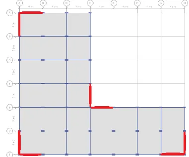
Figure 1: Plan of Model 2 (bracing locations are marked with red line)
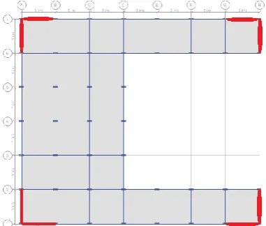
The bracing positions are marked with red colour. Equal number of bracings provided in Model No. 2, 4 and 6 to keep the weight of the structure same during comparison.
Figure 3: Plan of Model 6 (bracing locations are marked with red line)
Figure 4: 3D view of Model 2
Figure 5: 3D view of Model 4
Figure 6: 3D view of Model 6
B. Loading Details
For given structure loading is applied as per IS 875 part I, part II and IS 1893:2016.
Live load: 4kN/m2
Dead load: 1.5kN/m2
1) Earthquake Load Parameters :
TABLEII
EARTHQUAKELOADPARAMATERS
Earthquake zone V
Importance factor, I 1.2
Type of soil Medium soil (Type II)
Response reduction factor, R
5
Zone factor, Z 0.36
2) Time History Data :
Various time histories were applied to the structure and the response was checked. The following five time histories, which gave maximum response, were selected and used in further analysis.
Imperial Valley
Santa Monica
Friuli Italy
Gazli USSR
III.
RESULTS AND DISCUSSIONSAll the six models have been analysed using time history analysis to evaluate the seismic response of structure. Five different time histories are used for the analysis. The results are found in terms of maximum story displacement, story drift, base shear and column forces.
A. Maximum Story Displacement
Comparative study of maximum story displacement is shown in Fig 7, 8 & 9 and Table III, IV & V.
Imperial Valley S Monica Friuli Italy Gazli USSR El centro 25 50 75 100 125 150 175 200 225 250 189.01 205.44 167.39 152.47 145.24
54.87 64.77 48.27 77.95
52.54
Ma
x. Stor
y Disp. (
mm)
Time History
Without Bracing With Bracing
Figure 7: Plus Shape- Max. Story Displacement
Imperial Valley S Monica Friuli Italy Gazli USSR El centro 25 50 75 100 125 150 175 200 225 250 186.93 206.75 161.81 158.91 155.32 67.77 95.76 60.68 101.88 66.43 Ma x. Stor y Disp.( mm) Time History Without Bracing With Bracing
Figure 8: L Shape- Max. Story Displacement
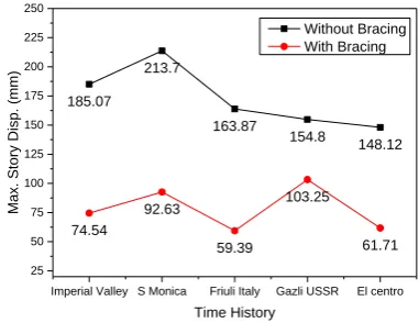
Imperial Valley S Monica Friuli Italy Gazli USSR El centro 25 50 75 100 125 150 175 200 225 250 185.07 213.7 163.87 154.8 148.12 74.54 92.63 59.39 103.25 61.71 Ma x. Stor
y Disp. (
mm)
Time History
Without Bracing With Bracing
Figure 9: C Shape- Max. Story Displacement
We can observe from figure that there is reduction in maximum story displacement to great extent after application of bracings.
TABLEIII
MAXIMUM STORY DISPLACEMENT-PLUS SHAPE
Max. story disp.(mm)
Plus Shape Percentage
reduction Model 1 Model 2 Imperial Valley
189.01 54.87 70.97
Santa Monica
205.44 64.77 68.47
Friuli Italy 167.39 48.27 71.16
Gazli USSR 152.47 77.95 48.87
El centro 145.24 52.54 63.83
Maximum story displacement in Plus shape model is reduced by 45% to 70% after addition of bracing system.
TABLEIV
MAXIMUM STORY DISPLACEMENT-L SHAPE
Max. story disp.(mm)
L Shape Percentage
reduction Model 3 Model 4
Imperial Valley
186.93 67.77 63.75
Santa Monica
Friuli Italy 161.81 60.68 62.50
Gazli USSR
158.91 101.88 35.89
El centro 155.32 66.43 57.23
Maximum story displacement in L shape model is reduced by 35% to 64% after addition of bracing system.
TABLEV
MAXIMUM STORY DISPLACEMENT-C SHAPE
Max. story disp.(mm)
C Shape Percentage
reduction Model
5
Model 6
Imperial Valley
185.07 74.54 59.72
Santa Monica
213.70 92.63 56.65
Friuli Italy 163.87 59.39 63.75
Gazli USSR 154.80 103.25 33.30
El centro 148.12 61.71 58.33
Maximum story displacement in C shape model is reduced by 33% to 64% after addition of bracing system.
B. Maximum Story Drift
Comparative study of maximum story displacement is shown in Table VI, VII & VIII.
TABLEVI
MAXIMUM STORY DRIFT -PLUS SHAPE
Max. story drift (mm)
Plus Shape Percentage
Reduction Model 1 Model 2
Imperial Valley
20.77 5.36 74.19
Santa Monica
25.17 6.99 72.23
Friuli Italy 18.98 4.51 76.24
Gazli USSR
23.98 8.14 66.06
El centro 18.09 5.35 70.43
Addition of bracings results in 65% to 76% reduction in maximum story drift in Plus shape model.
TABLEVII
MAXIMUM STORY DRIFT -L SHAPE
Max. story drift (mm)
L Shape Percentage
Reduction Model 3 Model 4
Imperial Valley
20.48 6.77 66.94
Santa Monica 25.67 9.94 61.28
Friuli Italy 18.64 5.81 68.83
Gazli USSR 25.30 10.95 56.72
El centro 19.43 6.36 67.27
Addition of bracings results in 55% to 67% reduction in maximum story drift in L shape model.
TABLEVIII
MAXIMUM STORY DRIFT -CSHAPE
Max. story drift (mm)
C Shape Percentage
Reduction Model 5 Model 6
Imperial Valley
19.65 7.57 61.48
Santa Monica 25.23 9.91 60.72
Friuli Italy 18.26 5.89 67.74
Gazli USSR 23.68 11.34 52.11
El centro 17.82 6.32 64.53
C. Base Shear
The base shear of all the three irregular buildings increases after addition of bracings. But the bracings add up very less weight so the increase in base shear is also very less i.e. 0.64% to 0.65%.
TABLEIX
BASE SHEAR OF BUILDING MODELS
Base shear (kN) X-
Direction Y- Direction
Plus Shape Model 1 4625.88 4625.75
Model 2 4655.57 4656.44
L Shape Model 3 4625.88 4625.75
Model 4 4656.11 4655.98
C Shape Model 5 4715.38 4715.25
Model 6 4745.61 4745.48
D. Column Forces
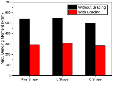
Addition of bracings reduces the bending moments in the columns. All the three buildings show reduction in BM as shown in Table X. On the contrary, there is increase in axial force as shown in Table XI.
TABLEX
MAXIMUM BENDING MOMENTS IN COLUMNS
Bending Moment (kNm)
Without Bracing
With Bracing
Percentage Reduction
Plus Shape 541.36 293.43 45.79%
L Shape 546.17 308.816 43.46%
C Shape 499.2739 285.297 42.86%
Plus Shape L Shape C Shape
0 100 200 300 400 500 600 700
Ma
x. Ben
ding
Mo
me
nt
(kNm)
Without Bracing With Bracing
Figure 10: Max. Bending Moment in Columns
TABLEXI
MAXIMUM AXIAL FORCE IN COLUMNS
Axial Force (kN)
Without Bracing
With Bracing
Percentage Increase
Plus Shape
4631.91 5385.76 16.28%
L Shape
4559.86 6136.37 34.57%
C Shape
4486.62 5880.82 31.07%
Plus Shape L Shape C Shape
0 1000 2000 3000 4000 5000 6000 7000 8000
Ma
x. Axial F
or
ce (
kN)
Without Bracing With Bracing
Figure 11: Maximum Axial Force in Columns
IV.
CONCLUSIONSamount of lateral displacement, bending moment. Following conclusions can be drawn from this study.
1) The additional weight of bracings applied is
473.44kN which is less than 1% of self-weight of structure. This little addition improves the performance considerably.
2) Bracing system effectively reduces lateral
displacements (up to 70%) and story drift (up to 75%) of the structure compared to bare frame.
3) Steel bracing also helps to reduce member
forces considerably.
4) In all the concept of using steel bracings in
reinforce concrete structures is advantageous to resist the earthquake forces.
V.REFERENCES
[1] Adithya, M., Swathi rani, K. S., Shruthi, H. K.,
Ramesh, B. R. (2015). "Study on effective bracing systems for high rise steel structures."
SSRG International Journal of Civil Engineering, 2(2), 21-25.
[2] Akhila, L. N. H., and Kumar, A. S. (2016).
“Dynamic analysis of an irregular RC building
with different bracing systems.” International
Journal of Science and Research, 5(7), 880-884.
[3] Alashkar, Y., Nazar, S., Ahmed, M. (2015). "A
comparative study of seismic strengthening of RC buildings by steel bracings and concrete
shear walls." International Journal of Civil and
Structural Engineering Research, 2(2), 24-34.
[4] Mehrabi, F. R., and Prasad, D. R. (2017).
"Effects of providing shear wall and bracing to seismic performance of concrete building."
International Research Journal of Engineering and Technology, 4(2), 890-896.
[5] Mishra, R., Sharma, A., Garg, V. (2014).
"Analysis of RC building frames for seismic forces using different types of bracing systems."
International Journal of Engineering Research & Technology, 3(7), 1135-1140.
[6] Narasimha, M. K., Darshan, S. K., Karthik, A. S.,
Santosh, R., Shiva Kumar, K. S. (2016)."Effective study of bracing systems for irregular tall steel
structures.” International Journal of Scientific &
Engineering Research, 7(5), 1059-1066.
[7] Naxine, D., and Prasad, R. V. R. K. (2016).
“Comparative study in the analysis of multistorey RCC structure by using different
types of concentric bracing system.”
International Journal of Engineering Sciences & Research Technology, 5(7), 483-488.
[8] Sangle, K. K., Bajoria, K. M., Mhalungkar, V.
(2012). “Seismic analysis of high rise steel frame
with and without bracing.” 15th World
Conference on Earthquake Engineering, Lisboa.
[9] Singla, S., Kalra, M., Kalra, R., Kaur, T. (2012).
"Behavior of RC framed building with different
lateral bracing systems." International
Conference on Advances in Civil Engineering,