© 2015, IRJET.NET- All Rights Reserved
Page 958
Application of Classical Lamination Theory and Analytical Modeling of
Laminates
Uttam. S. Koruche
1, Subhas. F. Patil
2,
1
Dept of Mechanical Engineering, KLE Dr. M.S Sheshgiri College of Engg & Tech, Belagavi, Karnataka, India
2Dept of Mechanical Engineering, KLE Dr. M.S Sheshgiri College of Engg & Tech, Belagavi, Karnataka, India
---***---Abstract -
Extensive research has been carried out onFRP (Fiber Reinforcement Polymer) composites and on variety of laminates. In this paper, work has been done
on unsymmetric 00/300/-450 graphite/epoxy laminate
and symmetric 00/900/00 graphite/epoxy laminate with
different mechanical and thermal loading conditions. Theoretical model is developed to show the mechanical response of a laminate. Determination of response of a laminate involves developing stress‐strain relations for a composite plate. The macromechanical analysis has been carried out for a laminate. Based on applied in-plane loads of extension, shear, bending and torsion, stresses and strains are found in the global axes of each ply. Stresses and strains in each ply are calculated for the laminates subjected to thermal loads. Analytical models developed helps to calculate fairly accurately mechanical properties of each lamina. Finally results are computed through CLT (Classical Lamination Theory) and ANSYS. Conclusion is drawn based on computed results.
Key Words:
CLT, graphite/epoxy, laminate and stress
1. Introduction
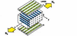
A lamina is a thin layer of a composite material that is generally of a thickness of the order of 0.125 mm. A laminate is constructed by stacking a number of such lamina in the direction of the lamina thickness (Figure 1).The design and analysis of laminated structures demands knowledge of the stresses and strains in the laminate. Also, design tools, such as failure theories, stiffness models, and optimization algorithms, need the values of these laminate stresses and strains. However, the building blocks (Figure 2) of a laminate are single lamina, so understanding the mechanical analysis of a lamina precedes understanding that of a laminate. A lamina is unlike an isotropic homogeneous material. For example, if the lamina is made of isotropic homogeneous fibers and an isotropic homogeneous matrix, the stiffness of the lamina varies from point to point depending on whether the point is in the fiber, the matrix, or the fiber–matrix interface. Accounting for these variations will make any kind of mechanical modeling of the lamina very complicated. For this reason, the macromechanical analysis of a lamina is
based on average properties and considering the lamina to be homogeneous [1].
Fig -1: Laminate with 3 lamina showing fiber and matrix
The thermo mechanical properties required for the analysis were obtained from tests on unidirectional laminates [2]. The fundamental solutions of concentrated forces and moments on an infinitely extended Unsymmetric laminate are developed and discussed [3]. It should be recognised that similar behaviour can also be achieved using less sophisticated designs, such as applying off-axis material
1. Fig -2: Lamina stacked to make laminate
alignment to otherwise balanced and symmetric laminates or by using un-balanced and symmetric design [4], Unsymmetric CFRP laminates are studied. These hybrid laminates are studied using analytical, finite element and experimental techniques [5]. Usually, uncoupling is obtained using symmetric stacking sequences, but in this case bending orthotropy is very difficult to be obtained [6]. The sensitivity of the FEM to model inputs and manufacturing accuracy was explored, and it was found that the laminate thickness and accuracy of ply angles were highly influential on the ability of the FEM to predict accurate deformations [7].
2. Statement of the problem
In this paper, study is done by taking 3 layer laminate composite, and calculating strains and stresses for different type of laminates with different orientation of lamina are stacked.
© 2015, IRJET.NET- All Rights Reserved
Page 959
In case 1: unsymmetric 0ₒ/30ₒ/-45ₒ graphite /epoxylaminate under biaxial loading (mechanical loading) without considering thermal loading condition is taken in to validation by classical lamination theory.
In case 2: symmetric 0ₒ/90ₒ/0ₒ graphite/epoxy laminate
under uniaxial loading along with thermal loading conditions under proper curing and room temperature is validated by finding strains and stresses through classical lamination theory. Now both cases are taken in to analytical validation through ANSYS. Results obtained from classical lamination theory and ANSYS mechanical APDL (ANSYS Parametric Design Language) are compared.
3.
Mathematical model
3.1 Stress-Strain Relations for an Orthotropic Material The Generalized Hooke’s Law of stress and strain of any
matrix, are stress components, are strain components
The Generalized Hooke’s Law for an Orthotropic Material reduces to
(3.3)
3.2 Hooke’s Law for Lamina under plane stress state A thin plate is a prismatic member having a small thickness, and it is the case for a typical lamina. If a plate is thin and there are no out-of-plane loads, it can be considered to be under plane stress. If the upper and lower surfaces of the plate
are free from external loads, then ,
and .This assumption then reduces the
three-dimensional stress–strain equations to two-three-dimensional stress–strain equations.
Fig -3:
Unidirectional laminaA unidirectional lamina falls under the orthotropic material category. If the lamina is thin and does not carry any out-of-plane loads, one can assume plane stress
conditions for the lamina. Therefore, taking ,
and .
Equation (3.3) for an orthotropic plane stress problem can then be written as
(3.4)
Inverting Equation (3.4) stress–strain relationship is,
(3.5)
Where are the reduced stiffness coefficients, which are related to the Compliance coefficients as Stiffness coefficients in terms of engineering or technical constants is
(3.6) = longitudinal Young’s modulus (in direction 1)
= transverse Young’s modulus (in direction 2) = major Poisson’s ratio, where the general Poisson’s = in-plane shear modulus (in plane 1–2)
3.3 transformed reduced stiffness matrix for angle lamina:
The coordinate system used for showing an angle lamina is as given in Figure 4. The angle between the two axes is denoted by an angle θ.
Fig -4: Angle lamina showing local and global axes
Relation between stress and strain in global axis is,
© 2015, IRJET.NET- All Rights Reserved
Page 960
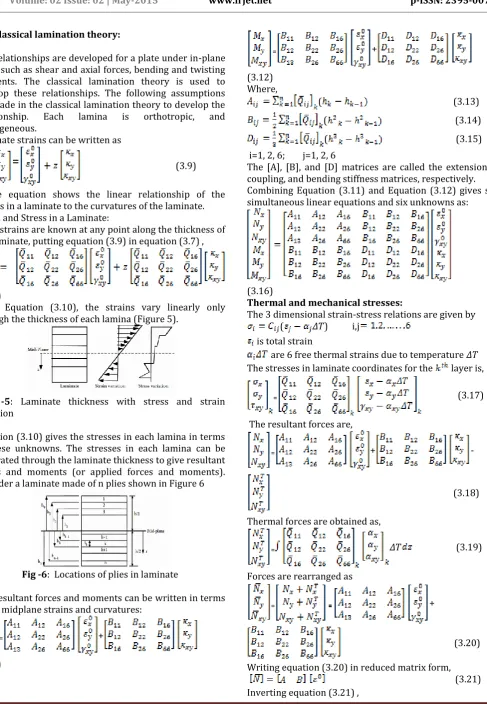
3.4 Classical lamination theory:The relationships are developed for a plate under in-plane loads such as shear and axial forces, bending and twisting moments. The classical lamination theory is used to develop these relationships. The following assumptions are made in the classical lamination theory to develop the relationship. Each lamina is orthotropic, and homogeneous.
Laminate strains can be written as
(3.9)
Above equation shows the linear relationship of the strains in a laminate to the curvatures of the laminate. Strain and Stress in a Laminate:
If the strains are known at any point along the thickness of the laminate, putting equation (3.9) in equation (3.7) ,
(3.10)
From Equation (3.10), the strains vary linearly only through the thickness of each lamina (Figure 5).
Fig -5: Laminate thickness with stress and strain variation
Equation (3.10) gives the stresses in each lamina in terms of these unknowns. The stresses in each lamina can be integrated through the laminate thickness to give resultant forces and moments (or applied forces and moments). Consider a laminate made of n plies shown in Figure 6
Fig -6: Locations of plies in laminate
The resultant forces and moments can be written in terms of the midplane strains and curvatures:
₌ + coupling, and bending stiffness matrices, respectively. Combining Equation (3.11) and Equation (3.12) gives six simultaneous linear equations and six unknowns as:
(3.16)
Thermal and mechanical stresses:
The 3 dimensional strain-stress relations are given by
( 𝛥𝛵) i,j
is total strain
are 6 free thermal strains due to temperature 𝛥𝛵 The stresses in laminate coordinates for the layer is,
₌ (3.17)
Writing equation (3.20) in reduced matrix form,
© 2015, IRJET.NET- All Rights Reserved
Page 961
(3.22)
4. Theoretical and analytical calculation 4.1 CLT theory on case 1:
Fig -7: Stacking sequence of graphite/epoxy laminate
In case one glass/epoxy laminate with 3 layered unsymmetrical 0, 30,-45 degree lamina stacked on one other, staking sequence is shown in figure 7.
Fig -8: Ply surface position and thickness
Stresses and strains are found by applying classical laminate theory on this laminate and obtained strains and stresses, and calculated strains and stresses for same model in ansys and compared these analytical values with theoretical readings obtained by classical laminate theory.
Table 4.1 Mechanical properties for graphite epoxy lamina [8]
Property symbol Units Graphite/epoxy
Fiber volume
Using equations from mathematical model, stresses are given as
4.2 Validating case 1 in ANSYS:
For 3 layered unsymmetrical 0,30,-45 degree graphite/epoxy laminate shell 181 is used as element. By using shell element laminate can be easily modeled. Where each shell thickness in case 1 is 0.005 m, Model is created by taking square cross section of each side of 1m and meshing is done by element edge length of 0.5, meshing is done for entire laminate at a time, 3 lamina are stacked on one other to get single laminate, each lamina consisting of matrix and fiber elements.
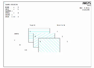
Fig -9: Lamina stacking sequence with fiber orientation representation
© 2015, IRJET.NET- All Rights Reserved
Page 962
Now to apply constraints, node at the centre of laminate isselected and all degrees of freedom set to zero. Loads of 1000 N/m is applied on laminate in both x and y directions.
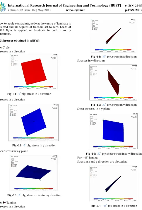
4.3 Stresses obtained in ANSYS:
For ply,
Stresses in x direction
Fig -11: ply, stress in x direction
Stresses in y direction
Fig -12: ply, stress in y direction
Shear stress in x-y plane
Fig -13: ply, shear stress in x-y direction
For lamina, Stresses in x direction
Fig -14: ply, stress in x direction Stresses in y direction
Fig -15: ply, stress in y direction Shear stresses in x-y plane
Fig -16: ply shear stress in x- y direction
For lamina,
Stress in x and y direction are plotted as
© 2015, IRJET.NET- All Rights Reserved
Page 963
Fig -18: ply stress in y directionShear stress in x-y plane
Fig -19: ply shear stress in x- y direction
Stresses for entire laminate, Stresses in x direction
Fig -20: Stresses in x direction for laminate
Stresses in y direction
Fig -21: Stresses in y direction for laminate
Shear stress in x-y plane of laminate
Fig -22: Shear stress in x-y plane for laminate
4.4 CLT theory on case 2:
In this case symmetric 0/90/0 degree graphite epoxy laminate is taken in to consideration and thermal loads are included under certain curing and room temperature along with mechanical loads .
Fig -23: 0/90/0 degree graphite epoxy laminate with fiber orientation
Layers are stacked on one other with green colour of fiber indicates 0 degree ply, blue colour indicates 90 degree ply. Since this cross-ply laminate having 3 layers, it is symmetric about it’s middle surface. This is the reason why, there is no coupling between bending and extension..Layer 1 is outer layer and fibers are in x direction, layer 2 is inner layer and fibers are in y direction, due to symmetry layer 3 is similar to layer 1.Thickness of both outer layers is equal to 0.127mm, Thickness of inner layer is equal to 10 times, thickness of outer layer 1.27 mm, Total laminate thickness is equal to 1.524mm.
Table 4.2 Mechanical properties of this graphite epoxy laminate [9]
Property symbol Units Graphite/
epoxy Longitudinal elastic
modulus
GPa 290
Transverse elastic modulus
GPa 6.9
Major Poisson’s ratio 0.25
Shear modulus GPa 4.8
Longitudinal
coefficient of thermal expansion
μm/m/°C -1.04
Transverse
coefficient of thermal expansion
© 2015, IRJET.NET- All Rights Reserved
Page 964
This composite was cured at 370 but is sitting in a roomat 70 . Thus we must consider the residual stresses resulting from the temperature difference.
Curing temperature 370 Room temperature Change in temperature
Stresses in each lamina is given as For lamina
For lamina
4.5 Validating case 2 in ANSYS:
Same size of laminate is modelled as taken in case 1 ,mechanical properties are also mentioned along with thermal coefficient of expansions and both curing and room temperature also specified in this case. Meshing is done in same way as in case one. Mechanical loading and uniform temperature are also specified to get final solution.
Fig-24: Stacking sequence of graphite/epoxy
Fig -25: Model of case 2 with element numbers
Stresses in case 2:
For lamina 1, Stress in x direction
Fig -26: stresses in x direction
Stresses in y direction
Fig -27: For lamina 2, stresses in x direction
Fig -28: Stresses in x direction
Stresses in y direction
Fig -29: Stresses in y direction
© 2015, IRJET.NET- All Rights Reserved
Page 965
Fig -30: stresses in x directionStresses in y direction
Fig -31: stresses in y direction
5. RESULT
Stresses calculated in both symmetric and unsymmetrical graphite/epoxy laminate with different mechanical and thermal loading condition by applying classical lamination theory and analysed in ANSYS. Thus obtained theoretical analytical studies on the damage initiation in composite laminates at cryogenic temperatures’, Original research article composite structures, Volume 76, 2006, pp. 62-66 . [3] Wilfried Becker, ‘Concentrated forces and moments on laminates with bending extension coupling’, Original research article composite structures, Volume 30, 1995, pp. 1-11.
[4] C.B. York, ‘On Extension–Shearing coupled laminates’, Original research article composite structures, Volume 120, 2015, pp. 472-482.
[5] Stephen Daynes, Paul Weaver, ‘Analysis of unsymmetric CFRP–metal hybrid laminates for use in adaptive structures’, Original research article Volume 41, 2010, pp. 1712-1718.
[6] E. Valot, P. Vannucc, ‘Some exact solutions for fully orthotropic laminates’, Original research article composite structures, Volume 69, 2005, pp. 157-166 .
[7] Robynne E. Murray, Darrel A. Doman, Michael J. Pegg , ‘Finite element modelling and effects of material uncertainties in a composite laminate with bend–twist coupling’, Original research article composite structures, Volume 121, 2015, pp. 362-376 .