Design of Higher Capability and Reliable long
Distance Network and Performance Analysis
Dr.T.Venkateswarlu1, Durgam Chaitanya Reddy2
Professor, Dept. of ECE, SVU College of Engineering, Tirupati, Andhra Pradesh, India1
M.Tech, Dept. of ECE, SVU College of Engineering, Tirupati, Andhra Pradesh, India2
ABSTRACT: This paper deals about the use of DWDM technique and its design. The DWDM technique refers to optical signals multiplexed in the range of 1550nm. It works effectively in the range of C-Band which has the wavelength from 1530-1565 nm. This technique enables us to increase the throughput by decreasing the usage of the medium which is the optical fibre. It deals with the twin concept of Optical transport network and Wavelength division multiplexing. By implementing in DWDM, the network gets optimised to have extended coverage area and maximization of bandwidth. DWDM terms like throughput, latency, Bit Error Rate, Optical Signal to Noise ratio are analysed by this technique.
KEYWORDS: DWDM (Dense Wavelength Division Multiplexing), multiplex, throughput, Optical transport network, Wavelength division multiplexing, latency, Bit error rate, Optical signal to noise ratio.
I. INTRODUCTION
The concept of combining many signals of different wavelength in a single optical fibre is called as the Wavelength Division Multiplexing. It has different types in it such as Broad WDM, Coarse WDM, and Dense WDM. Of which the Dense WDM has the major advantage in today’s data needs by transmitting signals over long distance at higher data rate. It multiplexes number of optical signals from different transmitters and transmits it through a single fibre. In the receiver end, all the different signals are split from the multiplexed signals. The major advantage of this technique is that it requires a single optical fibre medium instead of one fibre for a transmitter. This technique is protocol independent. This system provides greater bandwidth over any other existing optical system. This technique allows having a single fibre medium instead of handful of fibre for transmission of signals over long distance. It uses the Raman/ EDFA (Erbium Doped Fibre Amplifier) which gives the advantage that it does not require any regenerator for boosting the power of the signal frequently. The signal transmitted by this technique is 4 to 8 times better than the TDM (Time Division Multiplexing) signal and without regeneration it can be transmitted for about 300 Km. DWDM is well adaptive and can transmit variety of data which may differ in wavelength by bits in parallel or by character in serial manner. The emergence of this technique is an important phenomenon for optical transmission technology. It created the revolution by increasing the embedded fibre capacity. Networking industries faced the major issue of tremendous need for bandwidth. The development of optical networks along with the DWDM technique created the new network evolution.
The existing system of SDH (Synchronous Digital Hierarchy) and TDM (Time Division Multiplexing) can be opted for voice traffic and not the high speed data traffic. In order to support this need, very intelligent all-optical network device should be developed which will combine the features of SDH and the bandwidth increasing property of DWDM. The concept of optical fibre switching, loss control, packet switching and network topologies and synchronization has major role in the measure of throughput of the network.
II. LITERATURE REVIEW
Bharat T. Doshi et al.[1998] they evaluated alternative transport architectures for carrying IP-based traffic using the projected traffic data, nodal configuration, and optical fiber connectivity of a realistic, national-scale IP backbone. They compared the option of carrying IP directly versus IP over ATM for three types of transport architecture: SONET bidirectional line-switched rings (BLSRs), mesh networks of optical (or electrical) cross connects; and DWDMs without underlying optical cross connects (OXCs) that is, with one or more wavelength links between each pair of IP switches. These options also include restoration choices.
C. Develder et al [2004] they discussed optical packet switching (OPS) has been proposed as a strong candidate for future metro networks. This paper assesses the viability of an OPS-based ring architecture as proposed within the research project DAVID (Data and Voice Integration on DWDM), funded by the European Commission through the Information Society Technologies (IST) framework. Its feasibility is discussed from a physical-layer point of view, and its limitations in size are explored. Through dimensioning studies, they show that the proposed OPS architecture is competitive with respect to alternative metropolitan area network (MAN) approaches, including synchronous digital hierarchy, resilient packet rings (RPR), and star-based Ethernet.
Sorin Tibuleac and Mark Filer [2010] they described Reconfigurable optical add/drop multiplexers (ROADMs)
based on 1˟N wavelength-selective switches (WSS) are evolving to support DWDM networks with higher capacity and
increased flexibility in wavelength routing. Different WSS technologies can be employed to provide colourless and steerable functionality for ring, or meshed architectures. Improvements in specifications of WSS modules operating on the 50 GHz wavelength grid have enabled 40 GB/s transmission rates through extensive ROADM networks. The same ROADMs are also expected to support 100 GB/s transmission in the near future.
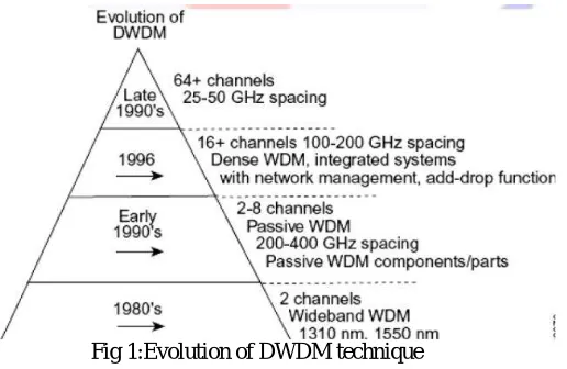
Fig 1:Evolution of DWDM technique
III.KEYCHARACTERISTICSOFDWDM
Here, we discuss the most important characteristics of the DWDM networks.
Component reliability, system availability and system margin is obtained by well- engineered devices.
An optical amplifier has two important components: the optical fibre with Erbium doped and an amplifier.
When laser is used to energize the erbium, it acts as the gain medium which amplifies the signal. The use of connector instead of medium results in the accumulation of dust which causes damage to the connector.
When a channel gets added or removed from the fibre, optical amplifier should be automatically adjusted for
optimal performance. When a signal with high power is transmitted, degradation in performance occurs whereas for low power, it is insufficient to provide enough gain for amplifier.
Silicon based optical amplifiers works similar as fluoride based optical amplifiers at the range of 1530 to 1565
nm. However fluoride based amplifier is costlier to implement.
Fig 2: Typical DWDM system
IV.DWDM SYSTEM COMPONENTS
Thefigure shows the typical DWDM networking components. The major components include:
Optical Terminal Multiplexer(OTM)
Optical Add Drop Multiplexer(OADM)
Optical Line Amplifier(OLA)
Optical Cross Connect(OXC)
A. OPTICAL TERMINAL MULTIPLEXER IT CONSISTS OF
Optical Transponder Unit (OTU)
Optical Multiplexer Unit (OMU)
Optical De-multiplexer Unit (ODU)
Optical Amplifier (OA)
Common Control Cards (NCP,OHP, OSC, LACT)
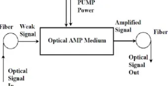
B. OPTICAL AMPLIFIERS
It amplifies the optical signals directly without need for the signal to be converted in to electrical form. It does not allow performing the OEO (Optical- Electrical- Optical)conversion. It increases the strength of the signal with addition of little amount of noise. It is an analog device which performs the amplification process with addition of some unwanted signals. IT is used to compensate the attenuation losses in the signal passing through the fibre.
We can use either EDFA (Erbium Doped Fibre Amplifier) or Raman Amplifier. Erbium doped Fibre Amplifier is the widely used optical amplifier for long range fibre optic communication. It amplifies light in 1.5μm wavelength region efficiently. This is of great importance to Telecom industry where they acquire minimum loss. Its application includes the boosting of the data transmitter power with EDFA amplifier for long distance fibre cable or for the fibre optic splitter which has maximum loss. Eg: Traditional Cable TV system now used, which transmits to several fibre using a single transmitter. Raman amplifier is now mostly attracted because of its smaller noise figure and cheaper than EDFA amplifier.
C. OPTICAL ADD DROP MULTIPLEXER
It is a device which is used to drop or add some wavelength while passing the remaining wavelength signal. It does not require any OEO (Optical- Electrical- Optical) conversion. We have fixed OADM as well as new generation OADM called ROADM (Reconfigurable Optical Add Drop Multiplexer). As per the situation ROADM can be configured using the software from remote station.
Fig 4: Optical Add Drop Multiplexer
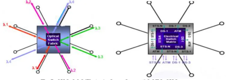
D. OPTICAL CROSS CONNECT
It is widely used in Telecommunication Industry for switching high speed optical signal into optical cables. Today’s OXC are very popular as it converts the optical data streams into electrical using Electronic cross connect and vice versa. This type is called as Hybrid or Opaque OXC. Another method of realising an OXC is switching the optical signals in all the optical devices. This type is called as Transparent or Photonic cross connect.
Fig 5: OXC-OOO(Photonic Cross Connect)&OEO-OXC
V. IMPLEMENTATION
VI.DESIGN
Here, we have designed a network of DWDM technique for different input wavelengths. The design goal is to achieve the transmission power and receive power of about +18±3 dB. The design has three sections, first is the transmitter part (OTM), then Add drop multiplexer, and the receiver part (OTM). The communication is through the optical fibre with the length of 360 Km and with spacing 0.8nm.
Fig 7:Design of 40 lamda DWDM
By taking 40 lamdas as input with 0.8nm spacing and with optical fiber length of 360km and by simulating the design without OADM and the output OSNR can be calculated in WDM analyzer after the loop i,e, end of the fiber optical signal as output that should be greater than 14db and BER analysis is taken as output.In BER analyzer the output less than 10-6 is good and less than 10-9 is excellent quality of signal.
In this DWDM design used for long distance. In this we can increase the distance than the present system by using OADM(optical add drop multiplexer).By this we can increase the quality and throughput of the signal.
VII. RESULT ANALYSIS
The output of the design 40 lamda DWDM without OADM in WDM analyser OSNR values should be greater than 14db as shown in following fig 9.
Fig 9: WDM analyzer without OADM
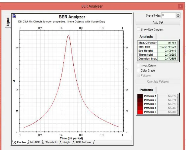
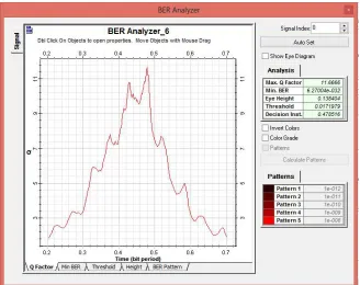
The output of 40 lamda DWDM without OADM in BER analysis displays the quality of the signal should be less
than 10-6 is good and less than than 10-9 is excellent quality of signal as shown in the following fig 10.
The output of the design 40 lamda DWDM with OADM in WDM analyser OSNR values should be greater than 14db as shown in following fig 11.
Fig 11:WDM analyser with OADM
The output of 40 lamda DWDM with OADM in BER analysis displays the quality of the signal should be less than
10-6 is good and less than than 10-9 is excellent quality of signal as shown in the following fig 12.
VIII. ADVANTAGES OF DWDM
In this section the advantages of implementing the system are discussed.
It increases the bandwidth in terms of both speed and distance.
There is no need for update or replacement of the existing system.
It allows less fibre cores to be used for transmission of high capacity of signals.
Allows using a single fibre core to have a maximum number of channels for transmission.
It provides easy expansion of network as a single fibre can be used for transmission; there is no need for extra
cables to be laid.
Low cost of expense as it uses the existing cable.
It has capacity to satisfy next generation data rate with high speed.
IX.CONCLUSION
This paper gives the brief discussion about the DWDM technique, its components and design of the network with efficient transmission of power. The Bit error ratio is also analysed. Since there is a very big need for huge data rate, this technique with enormous number advantage and application act as the base for the future communication needs. As stated above, this technique along with the current technique of SDH will have an absolute effective network formation to handle the increasing data rate. This technique will have some of the losses which may occur due to the dispersion of signal, splice loss, connector loss, insertion loss due to multiplexing number of wavelengths. Thus, DWDM technique is the most important milestone for the communication background in order to meet the huge demand of data rate.
X. ACKNOWLEDGEMENT
The author would like to thank Mr.Vetrivel and Dr.T.Venkateswarlu for their guidance in preparation of this
article and the issues faced in the design.
REFERENCES
1. J.G.Proakis, Digital Communication, 4th Ed.,McGraw-Hill,2000.
2. S.Walklin and J.Conradi, “Multilevel signalling for increasing the reach of 10Gbps light-wave systems”, J. Of lightwave Technol., vol.17, pp.2235-2248,1999.
3. E.Deservire, Erbium Doped Fibre Amplifiers: principles and Applications, Wiley, 1994.
4. ”DWDM pluggable transceiver multisource agreement (MSA) website.” [online]. Available: http://www.hotplugdwdm.org/. 5. ”Statistical Confidence levels for estimating error probability”, Maxim Engineering Journal, vol.37, 2007.
6. G.P.Agarwal, Lightwave Technology: Telecommunication Systems (Wiley, Hoboken, NJ, 2005). 7. R.Ramasami and K.Sivaranjan, Optical Networks (Morgan, San Francisco, 2009).
8. I.P.Kaminow, et al, ”A Wideband All-Optical WDM Network”, IEEE Journal on selected Areas in Communications”, vol.14, No.5, June 1996, pp.(780-799.)
9. http://www.ee.buffalo.edu/faculty/paololiu/566/Dense%20Width %20Division Multiplexing.ppt 10. https://aresu.dsi.crns.fr1/IMG/pdf/dwdm_ciena.pdf
11. http://yenista.com/DWDM-Transmitter.html 12. https://en.wikipedia.org/wiki/Optical_amplifier
13. J.M. Kahn and K.PoHo, “Modulation and Detection Techniques for DWAM Systems”, Optical Communication Theory and Techniques (Ed.) E.Foresrieri, ISBN: 978-0-387-23132-7, (2005).
14. S.Song,”DWAM and the Future Integrated Services Network”, IEEE Canadian Review,(2000). 15. G.P.Agrawal,”Fiber Optic Communication Systems”, 3rd Ed., Wiley,(2002).
16. ”Super-Channels DWAM Transmission beyond 100Gb/s”, by Infinera Corporation,(2012).
17. R.Ramaswami&K.Sivarajan, ”Optical Networks, A perspective” , Morgan Kaufmann Publication, 3rd edition, 2009. 18. Alberto Aloisio et.al., ”Performance Analysis of a DWAM Optical Transmission System”, 0018-9499, 2012 IEEE.