703
Wind Inter connection of Grid at the Distribution level
to improve the Power Quality by Using Resonant
Controller
Azra Zaineb1, J. Sridevi2
EEE, Department1,2,Geethanjali College of Engineering & Technology1 Gokaraju Rangaraju Institute of Engineering & Technology2
Email:[email protected]1,[email protected]2
Abstract- Sustainable power source assets are as a rule progressively associated in dispersion frameworks using power electronic converters. This Paper manages an exceptional control technique To beautify the Power excellent at the dissemination framework by making use of a four-leg Inverter. The Inverter is appearing multifunction in that ability as 1) manage converter to infuse manage constituted of RES to the network, and a pair of) shunt APF to repay modern-day unbalance, stack cutting-edge sounds, stack receptive strength request and load nonpartisan present day. This new control idea is exhibited with broad MATLAB/Simulink reproduction thinks about. The Performance was tried for Proposed Resonant controller and Conventional PI controller and THD is likewise thought about.
1. INTRODUCTION
Sustainable strength source is energy that is collected from inexhaustible belongings like daytime, wind, rain, tides, waves and geothermal power[1].Wind control is the usage of wind move thru breeze mills to mechanically manage turbines for electricity. Twist control,asan other to consuming petroleum products, is rich, inexhaustible, broadly appropriated, clean, creates no gas emanations all through task, expends no water, and uses next to no land[2]. The net impacts on the air are far less tricky than those of non-inexhaustible power sources. Wind control gives variable power, that is predictable from year to year however has vital variety over shorter time scales.
A breeze cultivate is a group of twist turbines inside a similar area utilized for generation of electrical power. A huge breeze homestead may incorporate numerous hundred individual breeze turbines appropriated over a broadened region. A breeze homestead may likewise be set seaward. Lion's share of all huge breeze turbines have comparative plan — a level pivot wind turbine having an upwind rotor with 3 sharp edges, snared to a nacelle over a tall tubular pinnacle..
2. SYSTEM DESCRIPTION
The proposed framework comprises of a breeze turbine framework which is associated with lattice through AC-DC-AC converter as appeared in Fig.1.Here AC to DC change is done through a Diode Bridge Rectifier(DRB) and DC to AC transformation is finished by 4-leg Voltage Source Inverter(VSI). A DC connect is utilized to interface AC-DC-AC converter and matrix. Also, network is associated with
704 is going about as a channel.
Because of the irregular idea of wind turbine framework, the produced control is of variable nature. The dc-connect assumes an necessary component in exchanging this variable electricity from wind turbine framework to the lattice. Wind turbine framework is spoken to as present resources related to the dc-connection of a community interfacing inverter[3]. Fig.2. demonstrates the precise outline of energy exchange from the breeze turbine framework to the network by means of the dc-connect. The current infused by wind turbine framework into dc-interface at voltage level Vdc can be given as
= (1)
Where is the power generated from RES.
The present day flow on the alternative facet of dc-hyperlink may be represented as,
= = (2)
Where Pinv, PG and PLoss are total energy to be had at grid-interfacing inverter facet, lively power provided to the grid and inverter losses, respectively. If inverter losses are negligible then PRES=PG.
3. CONTROL SYSTEM DESIGN
3.1 Control of Grid Interfacing Inverter:
The utilization of the four-leg electrical converter as a productive interface for inexhaustible and feasible dispersed vitality assets is picking up a ton of consideration with the advances in control gadgets innovation. One among the key advancements inverter based appropriated age (DG) frameworks is that the four-leg voltage source inverter (VSI) that is used to work in self-ruling four-wire microgrids. Four-leg VSI have turned out to be increasingly regular in four-wire microgrid, thus they can accomplish an appropriate control conspire in self-sufficient mode
however moreover manage the endorsed control quality needs.
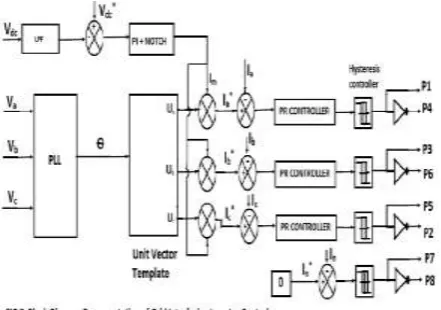
The control chart of framework interfacing inverter for a 3-stage 4-wire framework is appeared in Fig. 3. The fourth leg of inverter is utilized to repay the unbiased current of load. The principle point of proposed approach is to control the power at PCC during:1) PRES = 0; 2) PRES< add up to stack control (PL); and 3) PRES>PL .While playing out the power administration task, the 4-leg inverter is effectively controlled in a way with the end goal that it always draws/supplies central dynamic power from/to the network. In the event that the heap Related to the PCC is non-directly or unequal or the combo of every, the given control approach likewise repays the song, unbalance, and unbiased modern. The obligation proportion of inverter switches are shifted in a strength cycle with the quit aim that the combination of load and inverter infused manage shows up as adjusted resistive load to the lattice. The direction of dc-connect voltage conveys the information in regards to the trading of dynamic power in the middle of wind turbine framework and lattice. Hence the yield of dc-connect voltage controller brings about a dynamic current Im. The augmentation of dynamic current segment Im with solidarity matrix voltage vector formats (Ua, Ub and Uc) creates the reference framework streams (Ia*, Ib*and Ic*). The reference matrix impartial current is set to zero, being the quick entirety of adjusted network streams. The framework synchronizing point (Ɵ) acquired from stage bolted circle (PLL) is utilized to create solidarity vector format as [4]– [6].
Ua = Sin(Ɵ) (3)
Ub = Sin(Ɵ - ) (4)
Uc = Sin(Ɵ - ) (5)
705 do away with the presence of switching ripples at the
dc-hyperlink voltage and within the generated reference contemporary alerts.In order to inject into the grid, the same amount of energy that is being extracted from the windturbine system, a power balance is performed in the system through the dc-link voltage. The dc-link voltage,Vdc, is set to a fixed
reference value, Vdc*, that can only be keptconstant by
injecting the appropriate amount of current to the grid, ig. The dc-link voltage is controlled with a PI
controller augmented with a notch filter ―Eq.(6)‖, as can be seen in Fig. 3.
PI Notch(s) = ( + ) (6)
Where kpis the proportional gain, and ki is the integral
gain, ξzand ξ pare the damping coefficients of the
notch filter zerosand poles, respectively, and ωn is the
central frequency of thefilter[7]. It is to be noted that the controller gains are different to the PIcontrollers. The dc-link voltageerror at nth sampling instant is
and integral gains of dc-voltage regulator. The on the spot values of reference three phase grid currents are computed as
I*a = Im .Ua (9)
I*b = Im .Ub (10)
I*c = Im .Uc (11)
The impartial modern, gift if any, because of the masses connected to the neutral conductor have to be compensated via forth leg of grid-interfacing inverter and hence ought to not be drawn from the grid. In other words, the reference cutting-edge for the grid impartial present day is considered as zero and may be expressed as
I*n = 0. (12)
The reference grid currents (Ia*, Ib*, Ic* and In*)are in comparison with actual grid currents ( Ia, Ib, Ic and In ) to compute the modern-day-day errors as
Iaerr = I*a – Ia (13)
The immediate grid contemporary command, i*g, is injected into the grid by using the inverter, controlled with the aid of a proportional-resonant (PR) controller
PR(s) = kp+kr (17)
In which kp and kr are the proportional and resonant profits, respectively, and ωr is the resonant frequency. The proportional gain has a different value than the controllers previously described. This form of controller ensures zero monitoring blunders at the resonant frequency Which is ready to the grid frequency. The controller has been tuned to obtain a closed-loop bandwidth of 500 Hz, a worst-case disturbance rejection frequency reaction of −30 dB, and a resonant frequency of 50 Hz.
The output of PR controller is fed to hysteresis controller which generates switching pulses (P1 to P8) for the gate drives of four-leg VSI. These
Similarly the charging currents Iinvad, Iinvbd, Iinvcd, and Iinvnd on dc bus due to the each leg of inverter may be expressed as
IInvd = IInva(P1-P8) (21)
The switching pattern of each IGBT interior inverter may be formulated on the premise of error between actual and reference modern-day of inverter, which may be explained as:
If IInva<(I*Inva- hb), then upper switch S1 will be OFF (P1=0) and lower switch S4will be ON (P4=1) in the phase ―a‖ leg of inverter.
706 nonlinear load at PCC under shifting inexhaustible
creating conditions. A breeze turbine framework with variable yield control is associated on the dc-connection of lattice interfacing inverter. An unequal 3-stage 4-wire nonlinear load, whose unbalance, sounds, and responsive power should be adjusted, is associated on PCC.
The performance of the proposed control approach hassystem parameters as given in Table I.
Table1. System Parameters
S.No. Description Parameters
1 3-phase Supply(r.m.s)
Vg=100V,60Hz
2 DC link Voltage Vdc=300V
3 3-phase Non linear Load
R=26.66Ω, L=10mH
4 1-phase Linear Load (A-N)
R=36.66Ω, L=10mH
5 1-phase Non-Linear Load (C-N)
R=26.66Ω, L=10mH
6 DC-Link Capacitance & Voltage
Cdc=3000μF,Vdc=90V
7 Coupling Inductance
Lsh=2.0 Mh
The waveforms of grid voltage(Va,Vb,Vc), grid
currents (Ia,Ib,Ic,In), unbalanced load current
(ILa,ILb,ILc,ILn) and inverter currents(IInva, IInvb, IInvc, and
IInvn )are shown in Fig.4. The corresponding
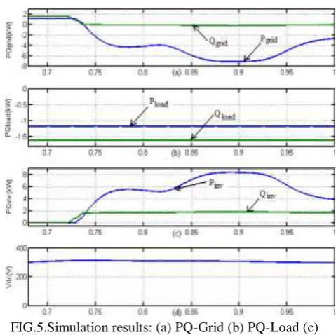
active-reactive powers of grid, load and inverter are shown in Fig. 4.
FIG.4.Simulation results: (a) Grid Voltages (b)Grid Currents (c)Unbalanced load currents (d) Inverter currents
Positive estimations of lattice dynamic receptive forces and inverter dynamic responsive forces infer that these forces spill out of network side towards PCC and from inverter towards PCC, separately. The dynamic and receptive forces consumed by the heap are indicated by positive signs. The dynamic and responsive power streams between the inverter, load and matrix amid increment and lessening of vitality age from RES can be seen from Fig. 5. The dc-connect voltage over the matrix
interfacing inverter (Fig. 5(d)) amid various working condition is kept up at steady level so as to encourage the dynamic and receptive power stream. Along these lines from the reenactment comes about, it is obvious that the lattice interfacing inverter can be viably used to remunerate the heap receptive power, current unbalance and current music notwithstanding dynamic power infusion from RES. This empowers the network to supply/get sinusoidal and adjusted power at UPF.
FIG.5.Simulation results: (a) PQ-Grid (b) PQ-Load (c) PQ-Inverter (d)dc-link voltage
The Total Harmonic Distortion of grid currents for different phases for proposed and conventional approach is as shown in Table 2.
Table 2.Total Harmonic Distortion
Description Grid
Currents
THD (%)
Proposed
Phase a 6.88 Phase b 7.48 Phase c 6.64
Conventional
Phase a 14.12 Phase b 16.34 Phase c 15.37
5. CONCLUSION
707 The people group interfacing inverter with the
proposed system can be utilized to:
I) infuse genuine power produced from RES to the framework, and additionally,
ii) work as a shunt Active Power Filter (APF),
iii) The Total Harmonic bending (THD) is also decreased effectively.
This approach in this way wipes out the requirement for extra power molding gear to enhance the nature of energy at PCC. Broad MATLAB/Simulink reenactment comes about have approved the proposed approach and have demonstrated that the framework interfacing inverter can be used as a multi-work gadget.
REFERENCES
[1] Ellabban, Omar; Abu-Rub, Haitham; Blaabjerg, Frede (2014). "Renewable strength resources: Current reputation, destiny prospects and their permitting technology". Renewable and Sustainable Energy Reviews.39:748–764 [749]. Doi:10.1016/j.Rser.2014.07.113.
[2] Fthenakis, V.; Kim, H. C. (2009). "Land use and power technology: A existence-cycle analysis". Renewable and Sustainable Energy Reviews.
Thirteen (67):1465.
Doi:10.1016/j.Rser.2008.09.017.
[3] Mukhtiar Singh, VinodKhadkikar,Ambrish Chandra, Senior Member, ―Grid Interconnection of Renewable Energy Sources at the Distribution Level With Power-Quality Improvement Features‖ IEEE Trans. On Power Electronics,, Vol.26, no.1,pp.307- 315Jan. 2011
[4] Khadkikar, A. Chandra, A. O. Barry, and T. D. Nguyen, ―Application of UPQC to guard a touchy load on a polluted distribution community,‖ in Proc. Annu. Conf. IEEE Power Eng. Soc. Gen. Meeting,2006, pp. 867–872.
[5] Carlos Lumbreras, Juan Manuel Guerrero, Pablo Garcia, Fernando Briz, and David DazReigosa,, ―Control of a Small Wind Turbine in the High Wind Speed Region,‖ IEEE Trans. On Power Electronics,, Vol. 31, no.10,pp.6980-6991 Oct. 2016