ISSN(Online): 2319-8753 ISSN (Print): 2347-6710
I
nternational
J
ournal of
I
nnovative
R
esearch in
S
cience,
E
ngineering and
T
echnology
(A High Impact Factor, Monthly, Peer Reviewed Journal) Visit: www.ijirset.com
Vol. 7, Issue 10, October 2018
Implementation of Various Error Detection
and Correction Techniques in Communication
Sandeep Singh1, Neeraj Gupta2, Rashmi Gupta2
M. Tech Student, Dept. of ECE, Amity University Haryana, Gurugram, India1
Assistant Professor, Dept. of ECE, Amity University Haryana, Gurugram, India2
ABSTRACT: To achieve high performance and better Quality Of data transmission, error detecting and correcting techniques are used. There are many different errors detecting and correcting techniques are available. It can improve the performance as well as the quality of the data transmitted.
When a digital signal is transmitted between two systems, the signal gets distorted because of the addition of noise to the transmitted signal. The noise can introduce an error is the binary train of bit travelling from one system to the other. This means that a 0 may change to 1 or a 1 may change to 0. This error can become serious problems with the accuracy and performance of the digital system. Therefore, it is essential to detect and correct the errors. In digital communication errors are introduced during the transmission of data from the transmitter to receiver due to noise or some other reasons. The reliability of data transmission gets severely affected and distorted because of these added errors on data. The detection and correction of transmission error added one or more than one extra bits during the time of transmitting the signal. The extra bits are known as parity bits. These parity bits detect or sometimes correct the errors.
KEYWORDS:Single bit error, Burst error, Parity check, Two-dimensional parity check, cyclic redundancy check, Error correction, Error detection
I.INTRODUCTION
ISSN(Online): 2319-8753 ISSN (Print): 2347-6710
I
nternational
J
ournal of
I
nnovative
R
esearch in
S
cience,
E
ngineering and
T
echnology
(A High Impact Factor, Monthly, Peer Reviewed Journal) Visit: www.ijirset.com
Vol. 7, Issue 10, October 2018
II.ERRORONCOMMUNICATION
A. Single Bit Error:
One is a single bit error, suppose sending a bit sequence may be a character says 0 0 0 0 0 0 1 0 an 8-bit ASCII code. There are sending one of the bits may get corrupted and it may become 0 0 0 0 1 0 1 0, this corresponds to a particular character and at the receiver, this has been transmitted.
Fig. 1.Single-bit error
This is very common in parallel transmission, suppose sending 8 bits simultaneously using 8 lines, so using 8 lines sending and whenever sending 8 bits, then one of the lines may be faulty, whenever a particular line is faulty obviously signal coming through the line will be in errors a result this will lead to a single bit error, if a particular line is faulty [3].
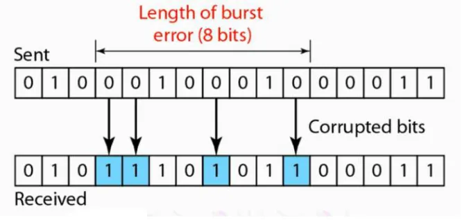
B. Burst Error:
Another type of error, which is known as burst error, burst errors occur whenever more than one bit gets corrupted. Suppose sending a long sequence 0 0 1 0 0 0 1 0 and so on, so the duration of noise is covering 4 bits. There is a possibility that some of these bits become 1. It is not necessary that all the bits will get corrupted so out of these 8 bits, the 4 bits have got correct, corrupted leading to signal at the other end of the receiving. This is essentially multiple bit error and call it burst error because a heavily noise is responsible for this kind of error.
ISSN(Online): 2319-8753 ISSN (Print): 2347-6710
I
nternational
J
ournal of
I
nnovative
R
esearch in
S
cience,
E
ngineering and
T
echnology
(A High Impact Factor, Monthly, Peer Reviewed Journal) Visit: www.ijirset.com
Vol. 7, Issue 10, October 2018
III. ERROR DETECTION TECHNIQUES
Simple Parity Check, Two-dimensional Parity check, Checksum, Cyclic redundancy check.
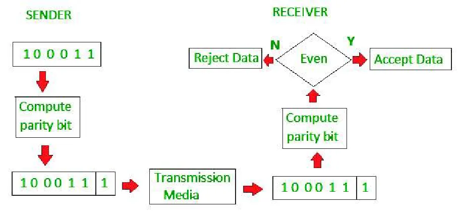
A. Simple Parity Check:
The most common approach is parity checking, which involves counting all the 1 bit in the data and adding one more bit to make the total number of 1 bit even (even parity) or odd (odd parity). The extra bit is called parity redundant bit. The method is also called vertical redundancy check (VRC). The performance of a simple parity check scheme, here all single bit errors are detected and it can detect all the single bit errors and also it can detect burst errors. However, this can detect burst errors only when the number of bits in error is odd, but when the number of bits in error is even. This technique is not foolproof again has burst errors that invert more than one bit, particularly if an even number of bits are inverted due to error, the error is not detected by using this simple parity check scheme.
Fig. 3. Even-parity checking scheme
So, to overcome this limitation, use two-dimensional parity checks. In two-dimensional parity check the performance is improved by using the number of bits that means more redundancy.
B. Two-dimensional Parity check:
ISSN(Online): 2319-8753 ISSN (Print): 2347-6710
I
nternational
J
ournal of
I
nnovative
R
esearch in
S
cience,
E
ngineering and
T
echnology
(A High Impact Factor, Monthly, Peer Reviewed Journal) Visit: www.ijirset.com
Vol. 7, Issue 10, October 2018
Fig. 4. Two-dimensional parity-check code
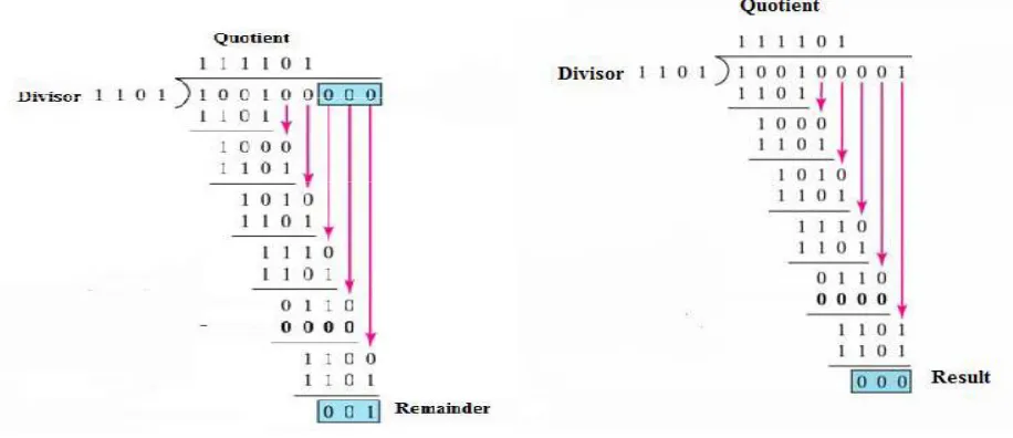
C. Cyclic redundancy check:
ISSN(Online): 2319-8753 ISSN (Print): 2347-6710
I
nternational
J
ournal of
I
nnovative
R
esearch in
S
cience,
E
ngineering and
T
echnology
(A High Impact Factor, Monthly, Peer Reviewed Journal) Visit: www.ijirset.com
Vol. 7, Issue 10, October 2018
Fig. 5. Mechanism of CRC at sender and Receiver side
ISSN(Online): 2319-8753 ISSN (Print): 2347-6710
I
nternational
J
ournal of
I
nnovative
R
esearch in
S
cience,
E
ngineering and
T
echnology
(A High Impact Factor, Monthly, Peer Reviewed Journal) Visit: www.ijirset.com
Vol. 7, Issue 10, October 2018
IV. ERROR CORRECTION TECHNIQUES
In error correction two basic approaches are used the first approach that is based on backward error correction. This backward error correction is based on this when an error is detected in a frame. The sender is asked to retransmit the data or a frame means that the receiver will check the error detector by one of the schemes. Then it will send information to the sender and ask the sender to retransmit the frame once again. This approach is known as automatic repeat request and this scheme is known as backward error correction, because going back to transmission once again and this particular scheme.
Positive ACK:When the receiver receives a correct frame, itsendsacknowledge to the sender.
Negative ACK: When the receiver receives a damaged frame or error frame, it sends a NACK back to the sender and
the sender again retransmit the correct frame.
Retransmission: The sender sends the data and maintains a clock limit and sets a fix timeout period. If an acknowledgement of a data-frame previously transmitted does not arrive before the timeout at the transmitter time period. The sender understand data was loosed and not reach to transmitter, it again sends data frame and wait for acknowledgement.
There are three types of techniques available for control the errors by Automatic Repeat Requests (ARQ).
(1) Stop-and-wait ARQ, (2) Go-Back-N ARQ, (3) Selective Repeat ARQ
ISSN(Online): 2319-8753 ISSN (Print): 2347-6710
I
nternational
J
ournal of
I
nnovative
R
esearch in
S
cience,
E
ngineering and
T
echnology
(A High Impact Factor, Monthly, Peer Reviewed Journal) Visit: www.ijirset.com
Vol. 7, Issue 10, October 2018
A. Forward error correction:
In forward error correction, send a frame specially encoded such that in some cases, the receiver can correct the errors but, in some cases, they couldn't correct errors. There were certain cases, where it's not perfect. So, we still need some way to ask the sender to retransmit to send again for example, send a frame and because of errors it doesn't get to the destination, it says that's a lost frame. On this method, Sender sends a frame to the destination and the destination sends back an ACKthat frame is a positive acknowledgment. If received the frames with errors on this approach receiver give a negative acknowledgement and send a frame to the destination. The destination sends back a message NAK that frame sent me has errors, that's an acknowledgment that something's gone wrong and if detected something's gone wrong [2].
B. Automatic Repeat Request or ARQ:
When we combine that with a positive acknowledgement we'll need a timeout mechanism the approach. The sender sends a frame to the destination, and wait for a positive acknowledgment, if the destination receives that frame, it sends back a positive acknowledgement. If sending the frame and there's an error and the destination, doesn't receive the frame and waiting for a positive acknowledgement. So here implements a timeout mechanism, after sending frame wait for some time, if I don't receive the ACK within that time, then I'll assume, it's lost and resend or retransmit it. This process is called automatic repeat request or ARQ [9].
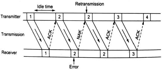
C. Stop-and-wait ARQ:
ISSN(Online): 2319-8753 ISSN (Print): 2347-6710
I
nternational
J
ournal of
I
nnovative
R
esearch in
S
cience,
E
ngineering and
T
echnology
(A High Impact Factor, Monthly, Peer Reviewed Journal) Visit: www.ijirset.com
Vol. 7, Issue 10, October 2018
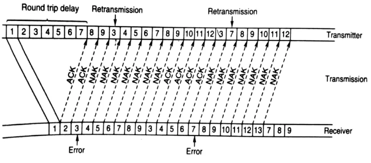
D. GO-Back-N ARQ:
At the receiver, the N-1 received vectors. Therefore, the receiver needs to store only one receive vector at a time. Because of the continuous transmission and we transmission support vector, then go back N ARQ scheme is more efficient than the stop and wait ARQ and it can be implemented at moderate cost communication protocols [5]. Then go back N ARQ scheme becomes inefficient when the round-trip delay is large and the data transmission rate is high. As shown in figure the transmitter transmits code vector 1 and does not wait for acknowledgement and its continuous transmit the next code vector 2 3 4 5 6 7 8 9 and receiver send the ACK and NAK. There for 3 respectively, then transmitter stop transmission of the code vector after 9. And firstly, retransmit the all data from 3 to 9 which was in not acknowledge from the receiver after that transmit next code vector.
Fig. 10. Go-Back-N ARQ
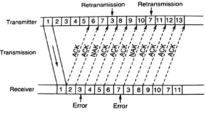
E. Selective repeat ARQ:
ISSN(Online): 2319-8753 ISSN (Print): 2347-6710
I
nternational
J
ournal of
I
nnovative
R
esearch in
S
cience,
E
ngineering and
T
echnology
(A High Impact Factor, Monthly, Peer Reviewed Journal) Visit: www.ijirset.com
Vol. 7, Issue 10, October 2018
Fig. 11. Selective Repeat ARQ
V.CONCLUSION
A cyclic redundancy checks this type of polynomial code is which is a bit string is represented in the form of polynomials with coefficients of 0 and 1 only. Polynomial arithmetic uses a modulo-2 arithmetic, i.e., addition and subtraction are identical to EX-OR. It is more powerful than the parity check and checksum error detection. The errors in communication system usually in bust error, the parity check method is not useful in detecting the errors under such conditions. The checksum error detection method can be used successfully in detecting such errors. In this method, the checksum is transmitted along with every block of data byte.
REFERENCES
[1] S G S Shiva K C Fung and H S Y Tan, (1970), “On Permutation Decoding of Binary Cyclic Double-Error-Correcting Codes of Certain Lengths”, IEEE Transaction on Information Theory, pp 641-643.
[2] Forouzan, “Data Communications and Networking”.
[3] I.S.Reed,“A class of multiple-error-correcting codes and thedecoding Scheme,” IRE Trans. Inf. Theory” , vol. IT-4, pp.38–49, 1954. [4] E.J.Weldon Jr., “Difference-set cyclic codes,” Bell SystemTech. J.vol. 45, pp. 1045–1055, 1966.
[5] Hamming, R W, (1950),” Error Detecting and Error Correcting Codes”, the Bell SystemTechnical Journal, Soc, Industrial Appl. Math., Vol. 26, No. 2.
[6] D J C Mackay, “Near Shannon limit performance of low-density parity check codes”, Electronics Letters, Vol. 33 N0. 6, 1997, pp. 457-458. [7] S. Lin and D. J. Costello, Error Control Coding: Fundamentals and Applications. New Jersey: Prentice-Hall, 1983.
[8] S B Wicker, (1994), Error Control Systems for Digital Communication and Storage, Prentice Hall Publishers. [9] George Clark and J Cain,” Error correcting code for digital communications” John Willey Publishers.