Range Migration Techniques for Short-Range MIMO Array Imaging
Jing Yang, Xiaozhou Shang, and Zhi-Ping Li*
Abstract—This paper presents a short-range imaging algorithm for multiple-input-multiple-output (MIMO) array. One of the steps in a previous method utilizes 2-D STOLT interpolation to transform 3-D data into 2-D data, which is not strict in the view of mathematical derivation and lack of physical meaning. The convolution operation which is analyzed by physical process of angular spectrum propagation is used to explain multi-static configuration and reduce the 3-D data into 2-D ones. This paper gives the physical phenomena of the whole process of imaging. We also explain the different physical meanings of FFT between transmitters and receivers. Numerical simulations show the consequence of STOLT interpolation in the previous algorithm and demonstrate the performance of the proposed algorithm.
1. INTRODUCTION
Nowadays, short-range human security screening equipment is strongly desired to have fast operational capabilities and mobility [1, 13, 14]. Synthetic aperture radar (SAR) [2] which gets the signal by relative movement between target and radar is often used in imaging of satellites and airplanes. The speed of imaging in these systems is slow because of mechanical of scanning. The antennas of a phased array radar [3] are distributed evenly and densely involving excessive communication bandwidth and cumbersome processing in hardware. Multiple-input Multiple-output (MIMO) [4] radar is an emerging radar system. It is composed of arrays of transmitters and receivers, and its Point Spread Function (PSF) is multiplied between patterns of transmitters and receivers. On one hand, MIMO radar can acquire data for a shot by using multiple parallel channels, which results in a quick image; on the other hand, it can achieve the same resolution using lower number of physical channels making it easily portable, because a coherent MIMO radar uses closely spaced antennas and allows coherent signal evaluation to improve resolution. The greatest strength of an MIMO radar is that it can perform well with fewer hardware resources but at the cost of putting more burden to software. Therefore, a kind of short range and fast imaging algorithm is a key part of an MIMO radar used in rapid human security instrument.
Typical imaging algorithms are Back Projection (BP) [6] and Range Migration (RM) [5]. The results of BP algorithm based on time and spatial domains are very accurate; however, it computes so slowly that it cannot satisfy rapid imaging requirements. On the other hand, RM algorithm is based on spectral domain. It computes quickly and also keeps result acceptably accurate. Therefore, RM algorithm will be a more suitable choice to study such applications.
At present, there are two kinds of MIMO radar standard algorithms, virtual array (VA)-RM [7] and MIMO-RM [8]. It is well known that the phase center of each group of transceivers is a virtual element for far-field situation. Regarding the short-range security applications, we need to compensate phase center error, but the option is limited. Since VA-RM algorithm cannot satisfy the requirement of
Received 1 September 2016, Accepted 21 October 2016, Scheduled 13 December 2016
* Corresponding author: Zhi-Ping Li (zhiping [email protected]).
short range, this algorithm will not be further explored in this paper. Whereas, MIMO-RM approach can achieve fast imaging using Fast Fourier Transform (FFT) over transmitter and receiver arrays. There have already been some papers [8, 12] discussing this approach; however, they do not explain the physical phenomena in much detail.
This paper describes the physical phenomena of MIMO-RM algorithm and is organized as follows. Section 2 presents the formulation of the MIMO range migration algorithm and its mathematical formulation. Then the process of convolution is detailed as a preferred alternative producing more precise results. Section 3 describes the algorithm implementation and data processing steps, in which we explain the different meanings of FFT over transmit arrays and FFT over receive arrays. Section 4 gives simulation results. Section 5 is the conclusion.
2. FORMULATION AND OPERATION OF CONVOLUTION
The essence of radar imaging is electromagnetic inverse scattering, which means that transmit arrays send electromagnetic waves to illuminate target which scatters the incoming radiation. Then, we measure the scattered field to get the geometric characteristics of this object. In order to quickly compute the problem, spectral domain imaging algorithm based on Discrete Fourier Transform (DFT) is used commonly. So the radar imaging process can be understood as finding the Fourier transform relationship between the radar echo data and the target characteristic function.
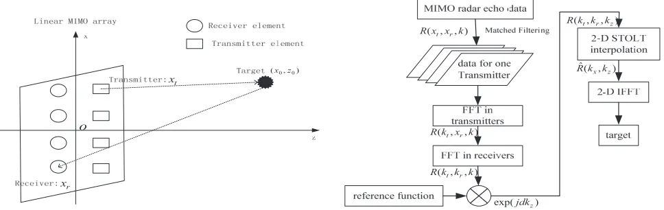
The MIMO linear array imaging geometry is illustrated by Figure 1. The Cartesian coordinate system O-XZ is established. x-axis and z-axis denote the azimuth and range directions, respectively. The locations of the target and antenna are both presented in the coordinate system. Assuming that the target’s characteristic function is A(x0, z0), the locations of transmit and receive arrays are xt and xr, respectively. Figure 1 shows the two-way propagation path of an MIMO radar system.
0 0
(x,z) t
x
r x
o
Figure 1. Imaging system geometry of the linear MIMO array.
( , , )t r R x x k
( , , )t r R k x k
( , , )t r R k k k
ˆ( , )x z R k k
exp(jdkz)
( , , )t r z R k k k
Figure 2. Block diagram of previous method of MIMO range migration.
According to Huygens-Fresnel principle [9], MIMO radar echo data R(xt, xr, k) is integral of all target scatters along various propagation directions. Since we care about focus position, the following derivation will ignore the influence of amplitude.
R(xt, xr, k) =
x0,z0
A(x0, z0)e−jkRte−jkRrdx0dz0 (1)
where k = 2πf /c is the wave number with c denoting the speed of light, f the frequency, and the exponential term represents a spherical wave propagation model. Rt andRrare the distances from the transmitter and receiver to the target, respectively, as given in the following.
Rt=
(xt−x0)2+ (d+z0)2 Rr =
where dis the distance between transmit/receive element and the center of target andz0 the distance between the center of target and other points on target.
Fourier transform is done alongxtand xr, then the method of stationary phase (MSP) [12] is used to solve integral as follows:
R(ktx, krx, k) =
x0,z0
A(x0, z0)e−jkz(z0+d)e−jkxx0dx0dz0 (3)
After acquiring spectral domain data, the form of no relation with integral variate is moved to the left of the equation.
R(ktx, krx, k) exp(jkzd) =
x0,z0
A(x0, z0)e−jkxx0e−jkzz0dx0dz0 (4)
wherekz =
k2−k2 rx+
k2−k2
tx,kx=krx+ktx (wave dispersion relation).
According to wave dispersion relation, the previous method uses STOLT interpolation to transform 3-D echo data (kt, kr, k) to 2-D target spatial spectrum (kx, kz), then construct the target image using 2-D inverse fast Fourier transform (IFFT). Figure 2 shows a data flow diagram of the whole imaging process. However, it is achieved by mathematic process. As we can see, it loses 1-D information because right-hand side of formula (4) is a 2-D integral whereas the left-hand side is 3-D echo data.
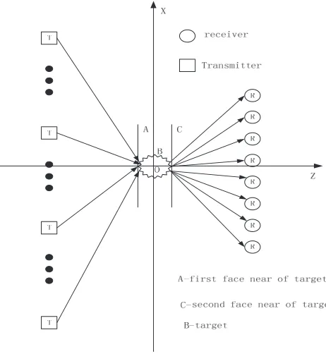
Through describing MIMO radar imaging process, this paper will show the physical process of electromagnetic waves propagation clearly, and explain how to solve the problem of transformation from 3-D echo data to 2-D target spatial spectrum. The convolution method is testified in the following text. Figure 3 shows a linear MIMO array which has several transmitters and receivers. In fact, transmit and receive antennas are set in the same line. In order to present the physical process of scattering in two-way propagation clearly, transmitters and receivers are drawn on opposite sides. Moreover, A is an incident field face and C a scattering field face, and both are close to B target. Transmitters T emit signal (e−jkxxt, only phase term preserved) which illuminates the target area B, and the incident field
is scattered by the isotropic scatter points in target area which is received by receiver R.
Figure 3. Electromagnetic wave propagation for MIMO radar.
( , , )t r
R x x k
( , , )t r
R k x k
( , , )t r
R k k k
exp(jdkz)
r
k
z
k
t
k
ˆ( , )x z
R k k
( , , )t r z
R k k k
target
In order to discuss the relation of propagation of electromagnetic wave, let a represent incident field, b represent target scattering character, and c represent scattering field. The FFT notations of these variables areA,B and C, which indicate the angular spectrum of incident field, target form and scattered field, respectively. The Fourier transform relations can be expressed as follows:
A=F F T(a), B=F F T(b), C =F F T(c)
According to scalar diffraction theory [10], the relation between field and target character is:
A⊗B =C where⊗ represents convolution.
The convolution can be solved by Fourier transform. Moreover, if a is a pure phase term, the following form is satisfied:
b=c×a∗
Now the target can be expressed in spectrum domain as follows:
B =C⊗A∗(−x) (5)
Therefore, the convolution ofC and A∗(−x) is the solution of targetB.
According to the angular spectrum solution of Helmholtz equation [11], the incident field A and scattered field C can be expressed by the spectrum of transmitter and receiver signal:
A=e−jkxxt ·e−j √
k2−kx2(d+z0)
C=R(xt, kx, k)·ej √
k2−kx2(d+z0)
Substituting these relations into formula (5), the imaging process can be written as:
b= R(xt, kxa, k)·e−j(kx−kxa)xtdxt·ej √
k2−kxa2 (d+z0) ej
√
k2−(kx−kxa)2(d+z0)
dkxaejkxax0dkxdk
The first integral onxtindicates the coherent superposition of all transmitters, and the integral on other variables can be settled to satisfy a Fourier relation as follow:
b=
R(kx−kxa, kxa, k)ejkz(d+z0)ejkxax0dkxadkxdk (6)
whereR(kx−kxa, kxa, k) =
R(xt, kxa, k)·e−j(kx−kxa)xtdxt,kz =
k2−k2 xa+
k2−(k
x−kxa)2 In formula (6), the first integral on xt is replaced by Fourier transform along transmitters, and ejkzd is considered as the reference function. A 2-D integral on k
xa and kx is demanded to acquire the integral of kz. After these procedures, the target can be solved from a 2-D Inverse Fourier transform of R.
3. ALGORITHM IMPLEMENTATION
This section deals with the practical implementation of the proposed MIMO-RM. The image reconstruction procedure is separated into seven steps as shown in the flow chart in Figure 4.
data is superposed alongkx to complete the convolution, which results in 2-D data form. The final step is 2-D IFFT to transform back to space domain to get the target.
During the interpolation,kz should be a real value, because the incident field should be constituted by travelling waves from the transmitter, so do the constrain of the received field. Therefore, the following relation must be met; otherwise, the evanescent wave should be ignored.
k2 ≥k2r, k2 ≥kt2
In practical implementation, the data that do not satisfy the criteria in the wavenumber domain are valued zero. Another detail is to calculate the convolution for discrete data in formula (6). Transmit and receive arrays are fused into the same grid and sampled with the same rate and quantization, which can be computed by simple shift and summation.
The image of resolution is determined by several parameters. The range-direction resolution and azimuth-direction resolution can be written respectively as:
δz = c
2B δx=
λcR LT +LR
where B represents bandwidth,R the distance from antennas to the target, λc the cutoff wavelength, LT the length of transmitter array, and LR the length of receiver array.
4. SIMULATIONS AND ANALYSIS
In order to verify this proposed approach and explain the confusion of previous MIMO-RM method, this paper gives 1-D array simulation results for comparison using MATLAB. The MIMO radar echo data are generated by using Huygens-Fresnel principle to calculate the propagation phase shift, which can be recognized as a simplification of data after matched filtering in real scenario.
Both transmit and receive apertures of a linear MIMO array are located at a distance of 1.5 m from target area. Both transmit and receive antennas are spaced with 0.01 m step with a span of 0.44 m in total, and the number of antennas is 45. This indicates a resolving capability of 0.017 m in azimuth direction.
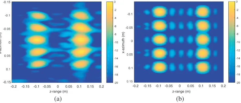
The target consists of a cluster of ten point scatterers distributed within an area of 0.1 m×0.1 m, five points along azimuth direction and two points along range direction. The frequency ranges from 28 GHz to 32 GHz, sampling a total of 201 points with a step of 20 MHz, which means 0.075 m of resolution in range direction.
Figure 5 compares the images obtained from previous method and the proposed method to show the focusing performance. The figure shows that the scatterer points in the previous method have high side-lobe and are not focused well. The reason is shown by their spectrum in Figure 6. We can see the lack of spectrum value of the previous method. This is caused by 2-D STOLT interpolation in 3-D data,
x-azimuth (m) x-azimuth (m)
z-range (m) z-range (m)
-0.2 -0.15 -0.1 -0.05 0 0.05 0.1 0.15 0.2
-0.15
-0.2 -0.15 -0.1 -0.05 0 0.05 0.1 0.15 0.2
(a) (b)
20 40 60 80 100 120 140 160 180 200 20 40 60 80 100 120 140 160 180 200
(a) (b)
Figure 6. Spectral distribution diagram after interpolation of (a) previous method, (b) proposed method.
Table 1. Compare the performance between previous and proposed method.
algorithm/performance side-lobe 3 dB beam-width computational time spectrum
previous method −9.96 dB 0.18 2.59 s missing
proposed method −11.21 dB 0.18 1.79 s integrity
because the spectrum should be calculated by a curve integral in the 3-D spectrum data and cannot be replaced by a single value of interpolation. However, the integral curve calculated in the convolution process in the proposed method acquires correct spectrum of target as shown in Figure 6(b). Table 1 shows the comparison of these two methods. Compared to the proposed method, the side-lobe level is higher and computational time is more with the previous method. Previous method consumes more time because of 2-D STOLT interpolation. The spectral distribution of previous method has some zero values, which result in high side-lobe level.
5. CONCLUSION
This paper puts forward the process of MIMO imaging according to physical phenomenon. The convolution relation is reviewed to interpret the implementation of STOLT interpolation in MIMO-RMA. The different meanings of FT between transmit and receive arrays are discussed. Finally, the results of simulation of the previous method and proposed approach are analyzed. The simulation demonstrates that the proposed method performs well on focusing and is an available algorithm for MIMO image.
REFERENCES
1. Kirschner, A. J., J. Guetlein, S. Bertl, et al., “A millimetre-wave MIMO radar system for threat detection in patrol or checkpoint scenarios,” SPIE Security + Defence, International Society for Optics and Photonics, 85440I-85440I-11, 2012.
2. Chen, C. C. and H. Candrews, “Target-motion-induced radar imaging,” IEEE Transactions on Aerospace &Electronic Systems, Vol. 16, No. 1, 2–14, 1980.
3. Greenwald, R. A., K. B. Baker, R. A. Hutchins, et al., “An HF phased-array radar for studying small-scale structure in the high-latitude ionosphere,”Radio Science, Vol. 20, No. 1, 63–79, 1985. 4. Li, J. and P. Stoica, “MIMO radar with colocated antennas,” IEEE Signal Processing Magazine,
5. Zhuge, X. and A. Yarovoy, “Near-field ultra-wideband imaging with two-dimensionalsparse MIMO array,”Proc. 4th EuCAP, 1–4, Apr. 2010.
6. Cui, G., L. Kong, and J. Yang, “A back-projection algorithm to stepped-frequency synthetic aperture through-the-wall radar imaging,” Asian and Pacific Conference on Synthetic Aperture Radar, 2007, Apsar 2007, 123–126, 2007.
7. Carrara, W. G., R. S. Goodman, and R. M. Majewski, Spotlight Synthetic Aperture Radar Signal Processing Algorithms, Artech House, Boston, MA, 1995.
8. Zhuge, X. and A. G. Yarovoy, “Three-dimensional near-field MIMO array imaging using range migration techniques,”IEEE Transactions on Image Processing, Vol. 21, No. 6, 3026–33, 2012. 9. Goodman, J. W. and M. E. Cox,Introduction to Fourier Optics, 2nd Edition, McGraw-Hill, 66–73,
1968.
10. Goodman, J. W. and M. E. Cox,Introduction to Fourier Optics, 2nd Edition, McGraw-Hill, 32–42, 1968.
11. Goodman, J. W. and M. E. Cox,Introduction to Fourier Optics, 2nd Edition, McGraw-Hill, 55–61, 1968.
12. Wang, H. J., “MIMO radar imaging algorithm,” National University of Defense Technology, 2010. 13. Dayi, F., R. Boehnke, M. Testar, et al., “Method for displaying an active radar image and handheld
screening device,” US9223018[P], 2015.