R E S E A R C H
Open Access
Three-dimensional shape measurement of
complex surfaces based on optimized
dithering fringe patterns
Feng Lu
1*, Chengdong Wu
1and Jikun Yang
2Abstract
Background:Optimized dithering fringe pattern is a promising method for high-speed, high-accuracy three-dimensional shape measurement. The recently proposed dithering optimization technology optimizes the fringe quality in either phase domain or intensity domain according to their objective functions. Phase-based optimization is direct and effective, but it is sensitive to projector defocusing levels. Intensity-based optimization is robust to projector defocusing levels, but it does not fully improve the phase quality. In practice, it is difficult to control defocusing levels so it is still a challenge to get high quality fringe patterns which affects the measurement quality under different defocusing levels.
Methods:In order to get high-quality binary dithered patterns which are robust to defocusing levels, this paper proposes a weight object function. This function combines two parts: a global intensity part and a local structure part. The global intensity measurement is based on the normalized mean squared error. The local structure measurement is based on residual error of intensity. To generate high quality fringe patterns, the weight object function is applied to the best patch framework.
Results and discussion:Both simulation and experimental results demonstrate that the phase-based optimization method and the proposed method perform better than the intensity-based optimization method under nearly focused. However the quality of measurement results from phase-based optimization will decrease with the defoucsing levels increasing. The proposed method is robust to the defocusing levels and it can still reduce the phase error when the projector is strongly defocused.
Conclusions:The proposed method can get high-quality binary dithered patterns under different defocusing levels by combining global similarity and local residual error of intensity. It inherits the merits of binary fringe pattern so that gamma calibration of projector is not required. In practice, the proposed method can be used to generate high quality fringe patterns. The experiment results verify that the proposed method can get better measurement results without considering the projector defocusing levels.
Keywords:Fringe analysis, Binary defocusing, Dithering, Optimization
* Correspondence:[email protected]
1Faculty of Robot Science and Engineering, Northeastern University,
Shenyang, China
Full list of author information is available at the end of the article
Introduction
In the past decades, digital fringe projection (DFP) methods have been proposed as one of the most reliable techniques to reconstruct the surface of objects because of their accuracy and efficiency [1–3]. Because it is easier and more convenient to generate fringe patterns and project patterns with a high speed, 3D shape measurement of dynamic objects has been rapidly expanding [4,5]. However, conven-tional DFP technique has major limitations: the projection nonlinearity and speed bottleneck [6–9]. These shortcom-ings make it difficult to be applied to high-quality and high-speed 3D shape measurement.
To overcome the bottleneck, binary defocusing tech-nique is recently developed which has successfully made speed breakthrough [10–12]. However, binary defocusing technique cannot achieve the same measurement capabil-ity compared with conventional DFP methods: (1) the measurement accuracy decreases due to high-frequency harmonics influence and (2) the measurement range is smaller since the projector must be properly focused for high-quality measurement [13–15]. Lately, pulse width modulation (PWM) [16] and optimal pulse width modula-tion (OPWM) [17] techniques are proposed to improve the fringe quality by eliminating high-frequency harmonics. However improvement is limited to wide fringe stripes, because the modulation is only one-dimensional without making full use of two-dimensional information.
Dithering technology is developed to take advantage of two-dimensional binary images so it could improve fringe quality of wide fringe stripes [18–21]. These techniques maintain low-frequency component so that the overall image is similar to the original pattern when a low-pass filter is applied. However, if fringe stripes are narrow, the improvement is rather small because high-frequency si-nusoidal fringe patterns are usually desirable since they provide better measurement quality when the period of fringe pattern is small.
Taking advantage of two-dimensional (2D) nature of the structured patterns, dithering optimization methods are developed for DFP systems [22–24]. According to their objective functions, these optimization methods can be classified into two categories: intensity-based optimization [25,26] and phase-based optimization [27,28]. The former makes the dithered pattern approximation for an ideal si-nusoidal fringe after defocusing. They are robust to pro-jector defocusing levels but they can not reduce phase errors efficiently. Since the ultimate goal of optimization is to generate high-quality phase, it is natural to optimize the pattern in the phase domain [29]. The latter makes the phase close to the desired linear phase when properly fo-cused. However, the phase-based optimization method is sensitive to different defocusing levels.
In order to address the aforementioned challenge, this paper proposes a weight object function combining
normalized mean squared error and intensity residual error. Instead of optimizing the whole pattern, our framework is optimizing pixels group by group to find the best binary patches, and then tiling the best patch to generate the full-size pattern utilizing symmetry and periodicity structure of the sinusoidal pattern. The pro-posed fringe patterns belong to dithering binary stripes so they inherit the property of dithering binary pattern which means that they can increase the measurement speed without using 8-bit information. It can also be used to overcome the gamma of projector without pro-jector non-linearity calibration. Moreover, these patterns can overcome the shortcomings from phase-based optimization and intensity-based optimization.
Both simulation and experiments demonstrate that the proposed method can achieve substantial phase quality improvements when the projector is at different de-focusing levels.
The rest of the paper is organized as follows. Section Methods explains the principles concerned in this tech-nique and the process of fringe pattern generation. Sec-tion Results and Discussion presents simulaSec-tion results, experimental results and the merits of the proposed technique. Section Conclusions summarizes this paper.
Methods
Three-step phase-shifting algorithm
Sinusoidal phase shifting algorithms are very widely used in conventional optical metrology due to their fast speed and high accuracy [30]. Typically, the more numbers of fringe patterns are used, the better measurement quality can be achieved. For high-speed 3D shape measurement, a three-step phase-shifting algorithm is usually adopted since it requires the minimum number of patterns to get the phase uniquely point by point. Since our research focuses on high-speed 3D shape measurement, a simple three-step phase-shifting algorithm with a phase shift of 2π/3is used to evaluate the proposed optimization algo-rithm. Three fringe images can be described as:
I1¼A xð ;yÞ þB xð ;yÞcos½φðx;yÞ−2π=3 ð1Þ
I2¼A xð ;yÞ þB xð ;yÞcos½φðx;yÞ ð2Þ
I3¼A xð ;yÞ þB xð ;yÞcos½φðx;yÞ þ2π=3 ð3Þ
Where A(x,y) is average intensity. B(x,y) is intensity modulation.ϕ(x,y) is the phase to be solved for:
ϕðx;yÞ ¼ tan−1 ffiffiffi 3 p
I1−I3
ð Þ
2I2−I1−I3 ð
4Þ
unwrapping method with three frequency phase-shifting algorithms.
Bayer-dithering technique
Dithering techniques have been developed to convert a higher bit depth into a lower bit depth, and this is analo-gous to halftone technique used in printing. Various dithering algorithms can be used to approximate an ideal sinusoidal fringe pattern, such as simple threshold-ing, random ditherthreshold-ing, and ordered dithering [31].
Among these dithering methods, Bayer-ordered dither-ing has been extensively utilized in many applications due to its simplicity and efficiency, which is adopted in this study. The Bayer dithering technique compares the original image with a2D grid of thresholds called Bayer kernel, and then the original image is quantized accord-ing to correspondaccord-ing pixels in the Bayer kernel: if the grayscale value is larger than the kernel, the pixel is turned to 1 (or 255 grayscale value), otherwise to 0. Neighboring pixels do not affect each other. Different kernels can generate completely different dithering ef-fects. Among the kernels used, Bayer has shown that if the sizes of the matrices are 2N(Nis an integer), there is an optimal dither kernel that results in the pattern noise being as high-frequency as possible. A low-pass filter can suppress the high-frequency noises. The Bayer kernel can be obtained by:
M1¼ 0 2
3 1
ð5Þ
Where M1 is the smallest base, and other larger pat-terns can be obtained by:
Mnþ1¼ 4 4Mn 4Mnþ2Un
Mnþ3Un 4MnþUn
ð6Þ
Where Un is n-dimensional unit matrix. In this re-search, we find that the Bayer kernel 8 × 8 produces the best results for all tested fringe stripes, and then it is utilized.
Weight objection function
Dithering optimization technique has been researched in reducing its overall phase error. The objective function of all these optimization techniques is to get the best fit of the binary patterns [32]. The optimization process can be described as a norm function such as Frobenius norm function:
min
B;G I xð ;yÞ−G xð ;yÞ B xð ;yÞF ð7Þ
Where ‖•‖ represents the Frobenius norm. I(x,y) is the ideal sinusoidal intensity pattern. G(x,y) represents a 2D Gaussian function. B(x,y) is a 2D binary pattern
and ∗ represents convolution. The optimization func-tion evaluates the global intensity similarity between the dithering pattern and its corresponding ideal pat-tern, but it just considers the global similarity without focusing on local structure similarity. In addition, NP problem makes it difficult to calculate the object func-tion [15].
The objective of all these optimization techniques is to obtain the best fit of the binary patterns which are close to the ideal sinusoidal pattern. The optimized binary patterns should be as close as possible to the ideal sinus-oidal patterns after applying Gaussian filter. The local detailed structure is one of the important resources in an image. It contains particular high-frequency compo-nents. In order to contain local similarity in the objective function, we propose a weighted object function (WOF). The objective function combines two parts: a global in-tensity part and a local structure part. The global inten-sity measurement is based on the normalized mean squared error (NMSE). The local structure measurement is based on the residual error of intensity (REI). If the intensity of ideal pattern areIand the intensity of dith-ering pattern isId,WOFcan be expressed as:
WOF¼ω1NMSE Ið;IdÞ þω2REI Ið;IdÞ ð8Þ
Where NMSE(I,Id) measures the global similarity and
REI(I,Id) measures the local similarity, respectively.
WOFgets the synthetic error between the ideal patternI
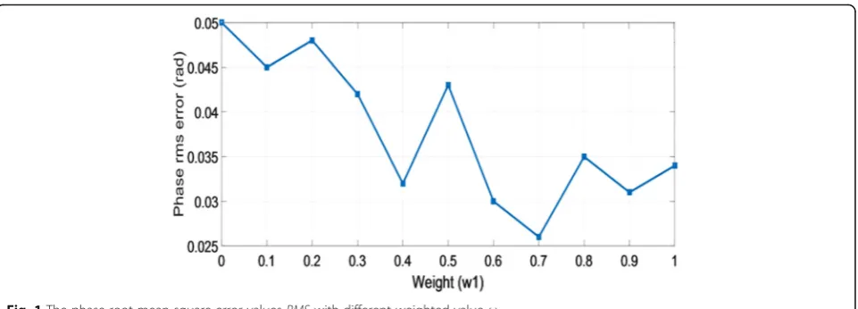
and the dithering patternId.ω1andω2are weighted fac-tors limited byω1+ω2= 1. Figure1illustrates phase root mean square error valuesRMS(rad) when weighted fac-torω1= 0~1. In order to simplify the description, we call it phase RMS error in the following parts. The lowest point of the broken line in Fig. 1 means the root mean square error valuesRMSvalue is the smallest whenω1is 0.7. Thus, in this research, we setω1= 0.7.
First a global intensity similarity is introduced into the WOF expression. NMSE(I,Id) can evaluate the global intensity similarity between the dithering pat-tern and the corresponding ideal patpat-tern. NMSE(I,Id) can be shown as:
NMSE Ið;IdÞ ¼
P
H
P
WðI xð ;yÞ−Idðx;yÞÞ2
P
H
P
WðI xð ;yÞÞ
2 ð9Þ
Because the existence of the third harmonics does not induce any phase errors for three-step phase-shifting algorithm [33], it can be proved that if the intensity error varies periodically at the frequency which is multiple of 3f0(f0is the fundamental frequency of the desired sinus-oidal pattern). The obtained phase map could be as same as the ideal phase map. The intensity error could not vary periodically but it is possible to separate the 3f0 harmonics from the total intensity error. Therefore, the intensity residual error functionREI(I,Id) is designed as:
REI Ið ;IdÞ ¼E xð ;yÞ−E3f0ðx;yÞ ð10Þ
E xð ;yÞ ¼G xð ;yÞ B xð ;yÞ−I xð ;yÞ ð11Þ
Where E(x,y) is the total intensity error between the defocused binary pattern and the ideal sinusoidal pat-tern. E3f0ðx;yÞ is the periodically harmonics.G(x,y) is a Gaussian function. B(x,y) is the binary dithered pattern. * is convolution. I(x,y) is the ideal sinusoidal pattern intensity.
It can be assumed that a periodical signal s(x) varies alongx direction for one period T(T = 3 N) ands3N(x) is one part of s(x). In order to extract the harmonicssN(x) from the whole signals3N(x), discrete Fourier transform is employed to obtain its spectrum S3N(k). After that, all those harmonics at the frequency (3l)thshould be retained and other harmonics should be removed. Therefore, the new sampled spectrumSN(k) can be described as:
SNð Þ ¼k S3Nð Þ k H kð Þ ð12Þ
H kð Þ ¼1
3comb
k
3 ¼
1 3
XN−1
l¼0
δ k
3−l
¼XN−1
l¼0
δðk−3lÞ
ð13Þ
Where H(k) is the Dirac comb function and every δ function is separated from each other at 3. According to
discrete Fourier transform theory and convolution principle, the filtering process in the spatial domain can be described as:
sNð Þ ¼x s3Nð Þ x h xð Þ ð14Þ
h xð Þ ¼ 1
3Ncomb x N ¼ 1 3N X2
m¼0
δ x
N−m
¼1 3
X2
m¼0
δðx−NmÞ
ð15Þ
Where h(x) is the spatial filtering function. ∗ repre-sents convolution. It turns out thath(x) is a Dirac comb function, but it is composed of threeδfunctions and the extent decreases to one-third. Therefore, the (3l)th
harmonics ofsN(x) can be solved for:
sNð Þ ¼x s3Nð Þ x δð Þ þx δðx−NÞ þδ x−
2N
ð Þ
3
¼s3Nð Þ þx s3Nðx−NÞ þs3Nðx−2NÞ
3
ð16Þ
Therefore, the (3l)th intensity error E3f0ðx;yÞ can be extracted from the intensity error E(x,y), which can be described as the following function:
E3f0ðx;yÞ ¼ 1
3 E x;ð yÞ þE xþ
T
3;y
þE xþ2T
3 ;y
ð17Þ
This function demonstrates a simple way to extract the (3l)th harmonics sN(x) out of signal without discrete Fourier transform. Firstly, s3N(x) is divided into three segments at the same lengthN. Secondly, three segments are added together to calculate an average segment. And finally, the (3l)thharmonicssN(x) are generated by period-ically extending the average segment along x direction three times. Then, the intensity residual error REI(I,Id) can be calculated.
Implementation in the best patch optimization framework
Instead of optimizing the whole fringe pattern, we use an idea which called binary patch, and then the patch are tiled to generate full-size patterns using symmetry and periodicity. Assuming that the desired sinusoidal fringe patterns vary alongxdirection: the best-fit binary pattern should be symmetric along x direction for one fringe period (T); and it should be periodic along theydirection. The period in every rowSyis defined as the period alongy direction. In this paper, we takeSx=T/2 as the patch col-umn period andTis the fringe period. The row periodSy for a best patch is set to different widths which are opti-mized respectively and from which the best one is chosen. This framework also includes two parts, the global inten-sity optimization and the further combined optimization. The process of optimization can be divided into the following major steps:
Step 1: Initial patch generation. Bayer dithered
sinusoidal fringes are generated firstly. The patch size of the row periodSyranges from 2 to 10. Then, according to the symmetry of the sinusoidal pattern and the optimization efficiency, the patch column periodSxis set toT/2 which is one half of fringe period.
Step 2: Patch optimization based on weighted error function. Each pixel (i,j) are mutated from 0 to 1 or
from 1 to 0. Because three step phase-shifting algorithm is used, there are eight groups: (0,0,0), (0,01), (0,1,0), (0,1,1), (1,0,0), (1,0,1), (1,1,0), (1,1,1). They are filtered by a Gaussian filter with size G= 5. Weighted error function is further optimized for
each group and the group error ζ is kept from the
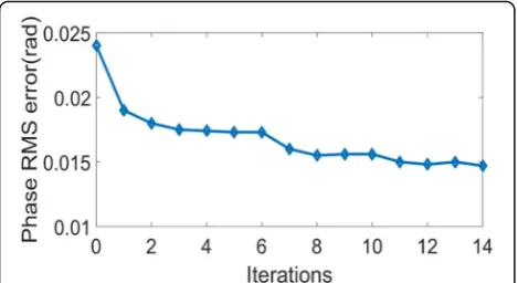
one with biggest absolute phase error to the smallest one. The further optimization is performed iteratively until phase RMS error is less than 0.01% or the number of iteration reaches maximum times.
Figure 2 shows the phase RMS error after each
round of optimization.
Step 3: Patch shifting. The global optimization binary patch is tiled and shifted to produce phase shifted fringes.
Step 4: Patch selection. After a number of patch mutations, a set of optimized patches are generated. From these patches, the best patch is selected based on the following two rules: (1) phase error does not change drastically if different sizes of Gaussian filter are applied; and (2) the resultant phase error is consistently small. These two rules imply that the best patch under one defocusing level may not be chosen.
Step 5: Fringe pattern generation. Utilizing symmetry and periodicity properties of fringe patterns, the desired size fringe pattern is generated by tiling the best patch together.
Figure3shows binary patterns before and after apply-ing the optimization algorithms. Figure 3a shows the desired sinusoidal pattern. The period of every fringe pattern is T= 20pixels. Figure 3b, c and d show three binary patterns comparison, which are respectively gener-ated by utilizing intensity-based optimization, phase-based optimization and the proposed method.
Phase-based optimization (p-opt) and intensity-based optimization (i-opt) are also two main categories to im-prove the quality of fringe patterns. In order to show the superiority of the proposed optimization method, we com-pare it with the norm Frobenius (NF), the p-opt [17], i-opt [14] and ideal sinusoidal fringe patterns under the same condition. Figure3shows the comparison among different
Fig. 3Example of binary patterns after applying different algorithms.aIdeal sinusoidal pattern (T= 20pixels);bintensity-based optimization
pattern;cphase-based optimization pattern;dproposed method optimization pattern
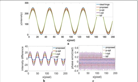
optimization. Figure4a shows the comparison between the ideal sinusoidal curve and cross-sections from different fringe patterns. Figure4b and c give the intensity difference and phase difference with i-opt, o-opt, NF and the pro-posed method. From the results we can find that the optimization framework can generate better quality and less phase error. Because NF just compares the global simi-larity without considering the local structure simisimi-larity, in the following section we just compare the intensity-based optimization, phase-based optimization and the proposed optimization.
Results and discussion
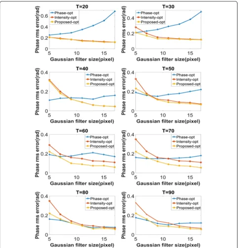
We evaluate the proposed algorithm through simulation where different periods are used. In this simulation, we use fringe periods T= 30,50,70 and 90 pixels. Different defocusing levels are expressed by applying different sizes of Gaussian filters. The size of Gaussian
filter-Granges from 5 to 17 and standard deviation isσ=G/3. When the size of Gaussian filter is 5 × 5 (σ= 5/3), it represents the case that the projector is nearly focused. When the size of Gaussian filter is 17 × 17 (σ= 17/3), it represents the case that the projector is defocused to a much more degree. In this simulation, the wrapped phase is obtained based on three-step phase-shifting algorithm and the phase RMS error is obtained by calculating the
difference between the phase obtained from the binary patterns and the phase obtained from the ideal sinusoidal fringe pattern. Figure5shows the phase RMS error com-parison among phase-based optimization (Phase-opt) [17], intensity-based optimization (Intensity-opt) [14] and the proposed best-patch optimization (Proposed-opt).
By analyzing the simulation, we can find that when the projector is nearly focused (Gaussian filter size is 5 × 5 and standard deviation is 5/3), the phase-based optimization has the lowest phase RMS error. When the period changes from 20 pixels to 90 pixels, the phase-based has the best phase quality. While with the Gaussian filter size increasing, the quality from phase-based optimization decreases because it is sensitive to filter sizes. When the pro-jector is slightly defocused (Gaussian filter size is 11 × 11 and standard deviation is 11/3 pixels). The phase error from the intensity-based optimization and the phase error from the proposed method decrease greatly as the filter size increases and they produce better results. They have the same tendency when the filter sizes increases. From simulation results, we can also find when the filter size is small, the proposed optimization almost have smaller phase RMS errors than the intensity-based optimization. It means that when projector is nearly focu-sed(the filter size is small), the proposed optimization can perform better than intensity-based optimization. Besides
Fig. 4The cross-section fringe comparison of different optimization.aThe comparison between ideal sinusoidal curve and cross section fringe
it is robust to defocusing levels. When the projector is slightly focused and strongly defocused (the filter size is large), the proposed optimization can still get high quality fringe pattern with less phase RMS error. Simulation has verified the superiority of the proposed optimization technique which can produce fringes with high phase quality under different de-focusing levels.
We also develop a 3D shape measurement system to verify the proposed method which consists of a DLP projector (Samsung SP-P310MEMX) and a digital CCD camera (Daheng MER-500-14U3M/C-L). The camera is attached with a 16 mm focal length lens (Computar M1614-MP) and the lens resolution is 1024 × 768. The resolution of projector is 800 × 600 and it has 0.49–2.80 m projection distance.
Fig. 7The deformed fringe pattern under different defocusing levels.athe deformed fringe pattern under nearly focused;bthe deformed fringe
pattern under slightly defocused;cthe deformed fringe pattern under strongly defocused
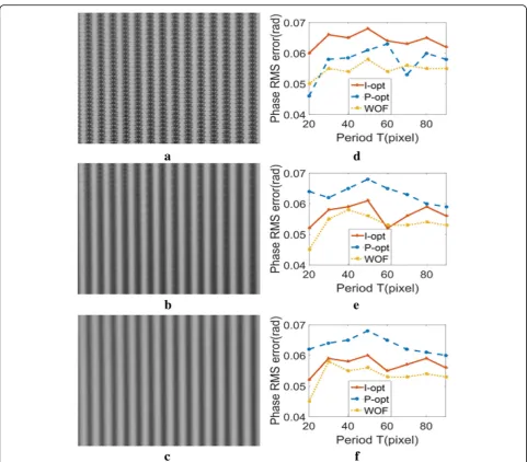
Fig. 6Experimental phase quality comparison among intensity-based optimization, phase-based optimization and the proposed method under
different amounts of defocusing.a-cshow dithering fringe patterns under different defocusing levels;d-fshow the corresponding phase
A uniform flat board is measured based on different optimization under three defocusing levels. Because phase-shifting algorithm with (n + 2) steps is insensi-tive to high-order harmonics up to thenth-order [20]. So in this research, the ideal phase is obtained by a ten-step phase-shifting algorithm and the period of fringe patterns is set to 20 pixels. Figure 6a-c show dithering fringe patterns which are optimized based on the proposed method from nearly focused, slightly defocused and strongly defocused respectively. Figure6d-f show the corresponding phase RMS errors and the phase RMS errors comparison from intensity-based optimization and phase-based optimization. This experimental re-sults show that when the projector is nearly focused, the proposed method and phase-based method have better phase quality and the intensity-based method has the largest rms error. With the defocusing levels in-creasing, the intensity-based method performs better than the phase-based method while the proposed method has small fluctuate. However phase errors are
still smaller. It indicates that the proposed method per-forms consistently well to get the better phase quality under three defousing levels.
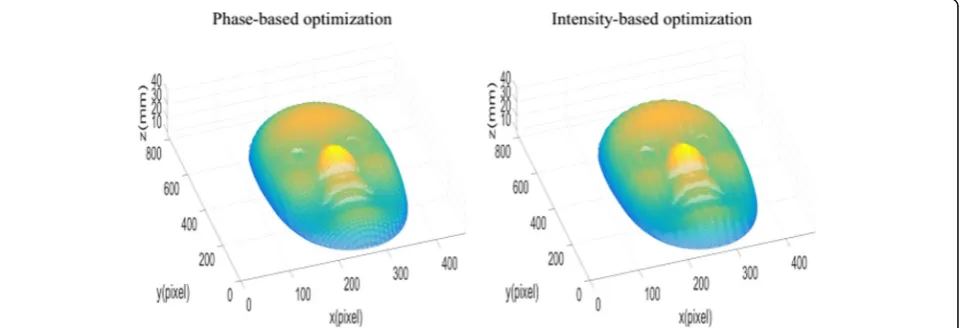
Furthermore, a more complex 3D statue is measured to compare these optimization methods under the same projector defocusing levels respectively. Figure 7 shows the deformed fringe pattern under nearly focused, slightly defocused and strongly defocused respectively. The measurement results are shown in Fig. 8. In order to compare the quality of results, Figs.9,10and11show the results based on phase optimization and the results based on intensity optimization at the same defocusing levels respectively. From the measurement results, it can be found that when the projector is nearly focused, the re-sult from the phase-based optimization appears slightly better than the intensity-based optimization method. Under slightly defocused and strongly defoucsed, the re-sults from the intensity-based optimization method have less errors than the results from phase-based optimization method. Because the proposed method decreases the
phase error and it optimizes the intensity errors, the pro-posed method can reconstruct smoother surface than both optimization methods.
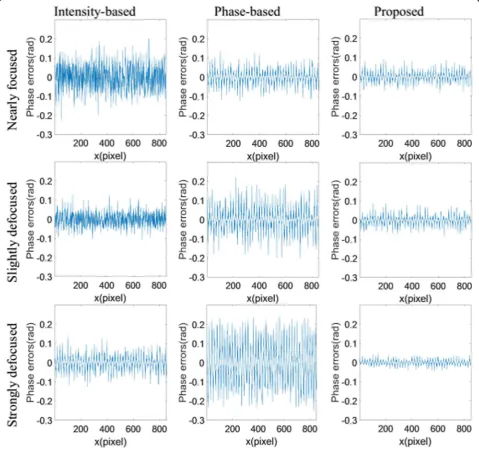
In order to give a more clear comparison, the phase er-rors of three dithering methods are calculated and they are shown in Fig. 12according to Figs. 8, 9, 10 and 11. When the projector is nearly focused, phase RMS errors of intensity-based optimization, phase-based optimization and the proposed optimization are 0.057 rad, 0.048 rad, and 0.045 rad. When the projector is slightly defocused, the corresponding phase RMS errors are 0.049 rad, 0.055 rad, and 0.045 rad for slightly defocused and when the projector is strongly defocused, the phase RMS errors are 0.045 rad, 0.058 rad and 0.042 rad. Table 1 lists the
corresponding measurement time based on Fig. 12. By comparison between the measurement time, it can be found that the proposed method can increase measurement speed.
These results also clearly show that phase-based optimization technology can improve phase quality
Fig. 12The phase error comparison of measurement results
Table 1The measurement time comparison between different optimization methods. (Unit:s)
P-opt I-opt Proposed method
Nearly focused 0.44 0.42 0.25
Slightly defocused 0.51 0.49 0.28
under a certain condition but it is sensitive to the amount of defocusing. The intensity-based optimization technol-ogy is able to improve the fringe quality with the defocus-ing levels increasdefocus-ing, but it can not reduce phase errors efficiently. The proposed technique has the same tendency with intensity-based optimization but it can increase the phase quality under different defocusing levels. The results are consistent with the simulation analysis.
Conclusions
This paper has presented an optimization method based on the weight objective function to generate high-quality sinusoidal fringe patterns. By using normalized mean squared error and residual error of intensity, the global similarity and local similarity can be optimized. Utilizing symmetry and periodicity properties of the fringe patterns, the desired fringe pattern is generated by tiling the best patch together. Simulation shows that the proposed fringes maintain high phase quality under different filter sizes. Experimental results also verify the feasibility and advantage of the proposed technique that the proposed method can generate high-quality binary fringes under dif-ferent defocusing levels.
Abbreviations
2D:Two-dimensional; 3D: Three-dimensional; DFP: Digital fringe projection; I-opt: Intensity-based optimization; NMSE: Normalized mean squared error; OPWM: Optimal pulse width modulation; P-opt: Phase-based optimization; PWM: Pulse width modulation; REI: Residual error of intensity; RMS: Phase root mean square; WOF: Weighted object function
Acknowledgments
This work was supported by National Key R&D Program of China (2017YBF1300900), the the National Natural Science Foundation of China (U1713216) and the Fund of Shenyang (17-87-0-00).
Funding
Faculty of Robot and Engineering of Northeastern University, Shenyang, China provides the funding for this research.
Availability of data and materials Details data has been provided in this paper.
Authors’contributions
All authors contribute equally in all the sections of this work. All authors read and approved the final manuscript.
Consent for publication Not applicable.
Competing interests
The authors declare that they have no competing interests.
Publisher’s Note
Springer Nature remains neutral with regard to jurisdictional claims in published maps and institutional affiliations.
Author details
1Faculty of Robot Science and Engineering, Northeastern University,
Shenyang, China.2Ophthalmology, General Hospital of Shenyang Military
Region, Shenyang, China.
Received: 19 April 2018 Accepted: 7 November 2018
References
1. Angelo, J.P., van de Giessen, M., Gioux, S.: Real-time endoscopic optical properties imaging. Biomed. Opt. Express.8(11), 5113–5126 (2017) 2. Reich, C., Ritter, R., Thesing, J.: 3-D shape measurement of complex
objects by combining photogrammetry and fringe projection. Opt. Eng.
39(1), 224–232 (2000)
3. Günther, P., Kuschmierz, R., Pfister, T., Czarske, J.: Distance measurement technique using tilted interference fringe systems and receiving optic matching. Opt. Lett.37(22), 4702–4704 (2012)
4. Feng, S., Zhang, Y., Chen, Q., Zuo, C., Li, R., Shen, G.: General solution for high dynamic range three-dimensional shape measurement using the fringe projection technique. Opt. Lasers Eng.59, 56–71 (2014)
5. Osten, W.: Application of optical shape measurement for the nondestructive evaluation of complex objects. Opt. Eng.39(1), 232–244 (2000)
6. Feng, S., Chen, Q., Zuo, C., Li, R., Shen, G., Feng, F.: Automatic identification and removal of outliers for high-speed fringe projection profilometry. Opt. Eng.52, 013605 (2013)
7. Zheng, D., Da, F.: Absolute phase retrieval for defocused fringe projection three-dimensional measurement. Opt. Commun.312(4), 302–311 (2014) 8. Zuo, C., Chen, Q., Gu, G., Feng, S., Feng, F.: High-speed three-dimensional
profilometry for multiple objects with complex shapes. Opt. Express.20, 19493–19510 (2012)
9. Heist, S., Kühmstedt, P., Tünnermann, A., Notni, G.: Theoretical considerations on aperiodic sinusoidal fringes in comparison to phase-shifted sinusoidal fringes for high-speed three-dimensional shape measurement. Appl. Opt.
54(35), 10541–10551 (2015)
10. Zhang, S., Van Der Weide, D., Oliver, J.: Superfast phase-shifting method for 3-D shape measurement. Opt. Express.18(9), 9684–9689 (2010)
11. Dreier, F., Günther, P., Pfister, T., Czarske, J.W., Fischer, A.: Interferometric sensor system for blade vibration measurements in turbomachine applications. IEEE Trans. Instrum. Meas.62(8), 2297–2302 (2013)
12. Heist, S., Lutzke, P., Schmidt, I., Dietrich, P., Kühmstedt, P.: High-speed three-dimensional shape measurement using GOBO projection. Opt. Lasers Eng.
87, 90–96 (2016)
13. Xu, Y., Ekstrand, L., Dai, J., Zhang, S.: Phase error compensation for three-dimensional shape measurement with projector defocusing. Appl. Opt.
50(17), 2572–81.6 (2011)
14. Takeda, M., Gu, Q., Kinoshita, M., Takai, H., Takahashi, Y.: Frequency-multiplex Fourier-transform profilometry: a single-shot three-dimensional shape measurement of objects with large height discontinuities and/or surface isolations. Appl. Opt.36, 5347–5354 (1997)
15. Wagner, C., Osten, W., Seebacher, S.: Direct shape measurement by digital wavefront reconstruction and multi-wavelength contouring. Opt. Eng.39(1), 79–86 (2000)
16. Ayubi, G.A., Ayubi, J.A., Di Martino, J.M., Ferrari, J.A., Di Martino, J.M., Ferrari, J. A.: Pulse-width modulation in defocused three-dimensional fringe projection. Opt. Lett.35(21), 3682–3684 (2010)
17. Wang, Y., Zhang, S.: Optimal pulse width modulation for sinusoidal fringe generation with projector defocusing. Opt. Lett.35(24), 4121–4123 (2010) 18. Garnica, G., Padilla, M., Servin, M.: Dual-sensitivity profilometry with
defocused projection of binary fringes. Appl. Opt.56(28), 7985–7989 (2017) 19. Zi-Xin, X.U., Chan, Y.H.: Removing harmonic distortion of measurements of a
defocusing three-step phase-shifting digital fringe projection system. Opt. Lasers Eng.90, 139–145 (2017)
20. Kite, T.D., Evans, B.L., Bovik, A.C.: Modeling and quality assessment of Halftoning by error diffusion. IEEE Int. Conf. Image Process.9(5), 909–922 (2000) 21. Kuschmierz, R., et al.: Optical, in situ, three-dimensional, absolute shape
measurements in CNC metal working lathes. Int. J. Adv. Manuf. Technol.
84(9-12), 2739–2749 (2016)
22. Dai, J., Li, B., Zhang, S.: Improve dithering technique for 3D shape measurement: phase vs intensity optimization[C]//Dimensional Optical Metrology and Inspection for Practical Applications II. Int. Soc. Opt. Photon. 8839, 883904 (2013)
23. Ettl, S., Kaminski, J., Knauer, M.C., Häusler, G.: Shape reconstruction from gradient data. Appl. Opt.47, 2091–2097 (2008)
25. Dai, J., Li, B., Zhang, S.: Intensity-optimized dithering technique for three-dimensional shape measurement with projector defocusing. Opt. Lasers Eng.53, 79–85 (2014)
26. Li, X.-X., Zhang, Z., Yang, C.: High-quality fringe pattern generation using binary pattern optimization based on a novel objective function. Opt. J. Light Electron Opt.127(13), 5322–5327 (2016)
27. Li, J., Hassebrook, L.G., Guan, C.: Optimized two-frequency phase-measuring-profilometry light-sensor temporal-noise sensitivity. JOSA A.
20(1), 106–115 (2003)
28. Dai, J., Zhang, S.: Phase-optimized dithering technique for high-quality 3D shape measurement. Opt. Lasers Eng.51(6), 790–795 (2013)
29. Li, B., Wang, Y., Dai, J., et al.: Some recent advances on superfast 3D shape measurement with digital binary defocusing techniques. Opt. Lasers Eng.
54, 236–246 (2014)
30. Sun, J.S., Zuo, C., Feng, S.J., Yu, S.L., Zhang, Y.Z., Chen, Q.: Improved intensity optimized dithering technique for 3D shape measurement. Opt. Lasers Eng.
66, 158–164 (2015)
31. Wang, Y., Zhang, S.: Three-dimensional shape measurement with binary dithered patterns. Appl. Opt.51(27), 6631–6636 (2012)
32. Dai, J., Li, B., Zhang, S.: High-quality fringe pattern generation using binary pattern optimization through symmetry and periodicity. Opt. Lasers Eng.
52(1), 195–200 (2014)
33. Zuo, C., Chen, Q., Gu, G., Ren, J., Sui, X., Zhang, Y.: Optimized three-step phase-shifting profilometry using the third harmonic injection. Opt. Appl.