i tif c n e C i o c n S f l e a r n e o n i c t e a 2 nr 0
et 1
1
n I
ISC 2011
Proceeding of the International Conference on Advanced Science,
Engineering and Information Technology 2011
Hotel Equatorial Bangi-Putrajaya, Malaysia, 14 - 15 January 2011
ISBN 978-983-42366-4-9
ISC 2011
International Conference on Advanced Science, Engineering and Information Technology
ICASEIT 2011
Cutting Edge Sciences for Future Sustainability Hotel Equatorial Bangi-Putrajaya, Malaysia, 14 - 15 January 2011
SR
IE AIV
UN IT NESIE DOKB
IN N
R AG
JA A L S A A E N P M N A A L U A T Y A S
S A I
REP
N I
NOI TAI COSSA STNEDUTS NA ISENOD Organized by Indonesian Students Association Universiti Kebangsaan Malaysia
Proceeding of the
Finite Element Analysis of Ultimate Load Capacity
of Slender Concrete-Filled Steel Composite Columns
Alireza Bahrami1, Wan Hamidon Wan Badaruzzaman,Siti Aminah Osman
Department of Civil and Structural Engineering, Universiti Kebangsaan Malaysia, Bangi, Selangor, Malaysia
1
Tel.:+60172685715, E-mail: [email protected]
Abstract— Ultimate load capacity of slender concrete-filled steel composite columns is investigated in this paper. Nonlinear analyses are done by the use of finite element software, LUSAS, to study the ultimate axial load behaviour of the columns. Verification of the finite element modelling is done by comparing the result with the corresponding experimental result reported by other researchers. Analyses are carried out to assess different shapes and number of cold-formed steel sheeting stiffeners with various thicknesses of cold-formed steel sheets and their effects on the behaviour and ultimate axial load capacity of the columns. The results are presented in the form of axial load-normalized axial shortening plots. It is demonstrated that the ultimate axial load capacity of the slender concrete-filled steel composite columns can be accurately predicted by proposed finite element modelling. Obtained results from the study show that various thicknesses of cold-formed steel sheets, and different shapes and number of stiffeners influence the ultimate axial load capacity and behaviour of the columns. Also, the ultimate axial load capacity of the columns is improved by increase of number of stiffeners. Moreover, increase of thickness of cold-formed steel sheet enhances the ultimate axial load capacity.
Keywords— Finite element analysis, Slender concrete-filled steel composite column, Ultimate axial load capacity, Cold-formed steel sheeting stiffener
I. INTRODUCTION
Concrete-filled steel composite columns have been increasingly used in civil projects worldwide, since they offer excellent structural benefits such as high strength, large stiffness, and high ductility. The critical local buckling stress of the steel sheet is improved by the concrete core. The steel sheet provides the confinement to the concrete which increases the strength and ductility of the concrete. Also, the role of the longitudinal and lateral reinforcement is served by the steel sheet and it acts as continuous formwork for the concrete which results in reducing construction costs.
Kloppel and Goder [1] conducted the earliest complete tests on concrete-filled steel tubes. 22 composite columns
with D/t ratios between 30 and 40 were studied by Gardner
and Jacobson [2]. Concrete-filled steel tubes under eccentric loading were tested by Neogi et al. [3]. Almost 270 circular, octagonal, and square composite columns were investigated by Tomii et al. [4]. Shakir-Khalil and Zeghiche [5] tested fourteen concrete-filled rectangular hollow section columns. Tests on nine 3-m long composite columns of concrete filled rectangular hollow sections and 12 short specimens were carried out by Shakir-Khalil and Mouli [6]. Grauers [7], Boyd et al. [8], and Morino et al. [9] reported tests on
walled steel tubular columns. Yu et al. [21] tested 28 thin-walled hollow structural steel columns filled with very high strength self-consolidating concrete. Bambach [22] reported experimental results of steel square hollow sections with externally bonded carbon fibre reinforced polymer. Experimental studies on circular concrete filled tube samples were performed by Chitawadagi et al. [23] to examine effect of parameters such as change in wall thickness of steel tube, strength of in-filled concrete, cross-sectional area of the steel tube, and length of the tube on the ultimate axial load and axial shortening of the columns. Tokgoz and Dundar [24] conducted 16 tests on concrete-filled steel tubular columns to investigate an experimental study on steel tubular columns in-filled with plain and steel fibre reinforced concrete.
Ultimate load capacity of slender concrete-filled steel composite columns under axial loading is the main focus of this paper. Proposed finite element modelling is verified by comparing the obtained result with the corresponding result from the test of the column done earlier by other researchers in [20]. Also, nonlinear finite element analyses are used to study different shapes and number of cold-formed steel sheeting stiffeners with various thicknesses of cold-formed steel sheets and their effects on the ultimate axial load capacity of the columns.
II. FINITE ELEMENT ANALYSIS
The finite element software LUSAS Version 14 was used to do the nonlinear analyses in this study. Modelling, convergence study, and verification of the method are presented in the following sections.
A. Modelling of the Columns
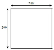
Cross-section of the concrete-filled steel composite column, UCFT 2-1 (without stiffener, mild steel) which refers to unstiffened concrete filled tube 2.34 m long, tested in the past by other researchers in [20], is shown in Fig. 1. 6-noded thin shell element TSL6 triangle in shape is chosen for steel sheet and 10-noded solid element TH10 is selected for concrete as the most appropriate elements. In order to obtain the ultimate axial load of the column due to buckling, the column must have some initial geometric imperfection. In this study, the small transverse force is used to create an initial geometric imperfection for the nonlinear analyses. A typical finite element mesh used for the slender
concrete-filled steel composite column is shown in Fig. 2. Support
conditions were appropriately modelled by restraining the nodes corresponding to the support points. Incremental displacement load with an initial increment of 1 mm is applied in the negative Y direction and acts axially to the column, simulating the load applied in the experiment.
Fig. 1 Cross section of the slender concrete-filled steel composite column (UCFT2-1, without stiffener, mild steel sheet of 2.5 mm, used in [20]) (All dimensions are in mm)
Fig. 2 Typical finite element mesh of the column used in the current study
The assumed uniaxial stress–strain curves for steel and concrete are shown in Fig. 3. Material properties for the concrete-filled steel composite column (UCFT2-1, without stiffener, mild steel) are given in Table I. Cold-formed steel sheet used in this study is BONDEK II with the yield stress,
fy, of 550 MPa.
Fig. 3 Typical stress–strain curves for steel and concrete
Table I
Material Properties for the Slender Concrete-Filled Steel Composite Column (UCFT2-1, Without Stiffener, Mild Steel) Used in [20] Material Poisson’s
Ratio υ
Elastic Modulus (MPa), Es
Yield Stress (MPa), fy
Compressive Strength (MPa), fc
Mild Steel 0.303 203000 270 -
Concrete 0.2 30600 - 58.3
B. Finite Element Discretization
Fig. 4 Results from the convergence study
C. Accuracy of the Finite Element Model
The concrete-filled steel composite column (UCFT2-1, without stiffener, mild steel) studied experimentally by Tao et al. in [20] was used to verify the finite element modelling in the present study. It is shown in Fig. 5 that the result obtained from the finite element analysis is very close to the one from the experiment. According the figure, the ultimate axial load capacity from the finite element analysis of the concrete-filled steel composite column (UCFT2-1, without stiffener, mild steel) is 2350 kN compared to 2305 kN from the experimental study which has 2% overestimation by finite element analysis. This approximation is within the acceptable accuracy and it is concluded from the verification study that the proposed finite element modelling is completely capable of predicting the behaviour of the columns in the study.
Fig. 5 Axial load-normalized axial shortening curves of the concrete-filled steel composite column (without stiffener, mild steel)
III. NUMERICAL ANALYSIS OF CONCRETE-FILLED STEEL COMPOSITE COLUMNS In view of the accuracy of the finite element model proposed, the method was used for the analysis of concrete-filled steel composite columns of same size and cross-section as the column (UCFT2-1, without stiffener, mild steel) tested by Tao et al. in [20], but with different thicknesses of cold-formed steel sheets and various shapes of the stiffeners namely V, T, Line, and Triangular stiffeners. Also, different number of the stiffeners was analysed. Furthermore, the effect of thickness of cold-formed steel sheet, and shape and number of the stiffeners on the ultimate axial load capacity and axial load-normalized axial shortening behaviour of the columns were investigated. Each of these columns was modelled as per the mesh mentioned
previously, appropriate restraints imposed at the boundaries and loading conditions incorporated. Following cross sections of the concrete-filled steel composite columns were analysed by the use of the finite element method. These can be divided into 4 categories and 8 subcategories. Figs. 6-9 show the cross sections of the concrete-filled steel composite columns with different number and shapes of the stiffeners.
1 on side 2 on side
Fig. 6 Cross sections of the concrete-filled steel composite columns (V stiffeners & cold-formed steel sheets of 1.5, 1.75 & 2 mm) (All dimensions are in mm)
1 on side 2 on side
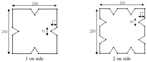
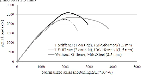
Fig. 7 Cross sections of the concrete-filled steel composite columns (T stiffeners & cold-formed steel sheets of 1.5, 1.75 & 2 mm)
1 on side 2 on side
Fig. 8 Cross sections of the concrete-filled steel composite columns (Line stiffeners & cold-formed steel sheets of 1.5, 1.75 & 2 mm)
1 on side 2 on side
Fig. 9 Cross sections of the concrete-filled steel composite columns (Triangular stiffeners & cold-formed steel sheets of 1.5, 1.75 & 2 mm)
IV. RESULTS AND DISCUSSION
Ultimate axial load capacities (Nu) obtained from the
nonlinear analyses of the columns based on various steel sheet thicknesses (t) and different number and shapes of the stiffeners are summarized in Table II, also axial load-normalized axial shortening plots for the columns are shown in Figs. 10 to 21.
Table II
Ultimate Axial Load Capacities of the Concrete-Filled Steel Composite Columns
No. Column t (mm) Nu (kN)
1 Without Stiffener, Mild Steel 2.5 2350
2 V Stiffener (2 on side) 1.5 2864
3 V Stiffener (2 on side) 1.75 3045
4 V Stiffener (2 on side) 2 3225
5 T Stiffener (2 on side) 1.5 2590
6 T Stiffener (2 on side) 1.75 2776
7 T Stiffener (2 on side) 2 2962
8 Line Stiffener (2 on side) 1.5 2263
9 Line Stiffener (2 on side) 1.75 2361
10 Line Stiffener (2 on side) 2 2516
11 Triangular Stiffener (2 on side) 1.5 2237
12 Triangular Stiffener (2 on side) 1.75 2341
13 Triangular Stiffener (2 on side) 2 2496
14 V Stiffener (1 on side) 1.5 2636
15 V Stiffener (1 on side) 1.75 2807
16 V Stiffener (1 on side) 2 2957
17 T Stiffener (1 on side) 1.5 2253
18 T Stiffener (1 on side) 1.75 2415
19 T Stiffener (1 on side) 2 2564
20 Line Stiffener (1 on side) 1.5 1880
21 Line Stiffener (1 on side) 1.75 2009
22 Line Stiffener (1 on side) 2 2141
23 Triangular Stiffener (1 on side) 1.5 1855
24 Triangular Stiffener (1 on side) 1.75 1976
25 Triangular Stiffener (1 on side) 2 2094
It can be perceived from the table and all the figures that the use of various thicknesses of cold-formed steel sheets with different shapes and number of the stiffeners is
effective on the ultimate axial load capacity of the columns.
For example, the ultimate axial load capacity of the column (without stiffener, mild steel) is 2350 kN which is improved to 3225 kN by the use of the column with V stiffener (2 on side) and steel sheet thickness of 2 mm, an increase of 37%. Also, it can be seen that the ultimate axial load capacity is enhanced by the increase of the number of steel sheeting stiffeners. For example, the ultimate axial load capacity of the column with Triangular stiffener (1 on side) and steel sheet thickness of 2 mm is 2094 kN which increases to 2496 kN when the column is made of two on side stiffeners, an enhancement of 19%. Moreover, according to the table and the figures, as the thickness of cold-formed steel sheet is increased from 1.5 to 2 mm the ultimate axial load capacity of the columns is enhanced which in most cases results into obtaining higher ultimate axial load capacity than that of the column without stiffener-mild steel. For example, the ultimate axial load capacity of the column with T stiffener (1 on side) is 2253 kN for the thickness of 1.5 mm, enhances to 2564 kN for the column with the thickness of 2 mm, an increase of about 14%. Meanwhile, the hierarchy of the different shapes of the stiffeners with same thickness of cold-formed steel sheet and same number of the stiffeners from the ultimate axial load capacity view is V, T, Line, and Triangular. For example, the ultimate axial load capacity of the columns with 2 on side stiffeners and cold-formed steel sheet thickness of 2 mm for different shapes of the stiffeners are 3225 kN, 2962 kN, 2516 kN, and 2496 kN, respectively for the columns with V, T, Line, and Triangular stiffeners.
Fig. 10 Axial load-normalized axial shortening plots for columns with different number of V stiffeners (cold-formed 1.5 mm) and without stiffener (mild steel 2.5 mm)
Fig. 12 Axial load-normalized axial shortening plots for columns with different number of Line stiffeners (cold-formed 1.5 mm) and without stiffener (mild steel 2.5 mm)
Fig. 13 Axial load-normalized axial shortening plots for columns with different number of Triangular stiffeners (cold-formed 1.5 mm) and without stiffener (mild steel 2.5 mm)
Fig. 14 Axial load-normalized axial shortening plots for columns with different number of V stiffeners (cold-formed 1.75 mm) and without stiffener (mild steel 2.5 mm)
Fig. 15 Axial load-normalized axial shortening plots for columns with different number of T stiffeners (cold-formed 1.75 mm) and without stiffener (mild steel 2.5 mm)
Fig. 16 Axial load-normalized axial shortening plots for columns with different number of Line stiffeners (cold-formed 1.75 mm) and without stiffener (mild steel 2.5 mm)
Fig. 17 Axial load-normalized axial shortening plots for columns with different number of Triangular stiffeners (cold-formed 1.75 mm) and without stiffener (mild steel 2.5 mm)
Fig. 18 Axial load-normalized axial shortening plots for columns with different number of V stiffeners (cold-formed 2 mm) and without stiffener (mild steel 2.5 mm)
Fig. 20 Axial load-normalized axial shortening plots for columns with different number of Line stiffeners (cold-formed 2 mm) and without stiffener (mild steel 2.5 mm)
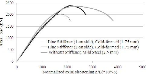
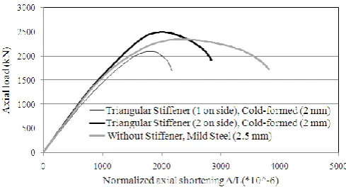
Fig. 21 Axial load-normalized axial shortening plots for columns with different number of Triangular stiffeners (cold-formed 2 mm) and without stiffener (mild steel 2.5 mm)
V. CONCLUSIONS
Behaviour and ultimate axial load capacity of the slender concrete-filled steel composite columns have been studied in this paper by the use of nonlinear finite element analyses. Accuracy of the finite element modelling of the columns was verified by comparison of the modelling result with the corresponding experimental study on the columns which can be concluded that the proposed three dimensional finite element modelling using LUSAS software is perfectly accurate to predict the ultimate axial load capacity and behaviour of the slender concrete-filled steel composite columns. The ultimate axial load capacity and the behaviour of the columns with different shapes and number of cold-formed steel sheeting stiffeners in various thicknesses of cold-formed steel sheets have been investigated and presented in this study by the use of nonlinear finite element analyses. It is concluded from the study that the use of various thicknesses of cold-formed steel sheets and different shapes and number of the stiffeners can affect the ultimate axial load capacity of the columns and in most cases it can be obtained higher than that of the column without stiffener-mild steel. Also, the ultimate axial load capacity of the columns is enhanced by the increase of the number of the stiffeners. Moreover, increase of the thickness of cold-formed steel sheet improves the ultimate axial load capacity of the columns. Meanwhile, the hierarchical order of different shapes of the stiffeners with same thickness of cold-formed steel sheet and same number of the stiffeners from the ultimate axial load capacity view is V, T, Line, and Triangular.
REFERENCES
[1] VK. Kloppel and W. Goder, ―An investigation of the load carrying
capacity of concrete-filled steel tubes and development of design formula,‖ Der Stahlbau, vol. 26(2), pp. 44–50, 1957.
[2] J. Garder and R. Jacobson., ―Structural behavior of concrete filled
steel tubes,‖ ACI J, vol. 65, pp. 404 –13, 1967.
[3] PK. Neogi, HK. San, and JC. Chapman, ―Concrete filled tubular steel
columns under eccentrical loading,‖ J Struct Eng, vol. 47(5), pp.
187–95, 1969.
[4] M. Tomii, K. Yashimaro, and Y. Morishita, ―Experimental studies
on concrete filled steel tubular stub column under concentric loading,‖ in Proc. of the International Colloquium on Stability of Structures under Static and Dynamic Loads, Washington: SSRC/ASCE, 1977, pp.718–41.
[5] H. Shakir-Khali and J. Zeghiche, ―Experimental behavior of concrete filled rolled rectangular hollow section columns,” Struct Eng; vol. 67(19), pp. 346–53, 1989.
[6] H. Shakir-Khalil and M. Mouli, ―Further tests on concrete-filled
rectangular hollow-section columns,‖ Struct Eng, vol. 68(20), pp.
405–13, 1990.
[7] M. Grauers, ―Composite columns of hollow steel sections filled with high strength concrete‖, PhD dissertation, Division of Concrete Structures, Chalmers University of Technology, Sweden, 1993. [8] FP. Boyd, WF. Cofer, and DI. Mc Lean, ―Seismic performance of
steel-encased concrete columns under flexural loading,‖ ACI Struct J, vol. May–June, pp. 355–64, 1995.
[9] S. Morino, K. Sakino, A. Mukai, and K. Yoshioka, ―US–Japan Cooperative Earthquake Research Program on CFT column systems‖ in Proc. of the 5th International Colloquium on Stability of Metal Structures, Chicago, 1996, pp. 83–92.
[10] M. A. Bradford, ‗‗Design strength of slender concrete-filled
rectangular steel tubes.‘‘ ACI Struct. J., vol. 93(2), pp. 229–235,
1996.
[11] A. E. Kilpatrick, ‗‗The behaviour of high-strength composite
concrete columns.‘‘ PhD thesis, Curtin University of Technology, Australia, 1996.
[12] B. Uy and S. B. Patil, ‗‗Concrete-filled high strength steel box
columns for tall buildings: behaviour and design.‘‘ Struct. Design
Tall Buildings, vol. 5, pp. 75–94, 1996.
[13] B. Uy and S. Das, ‗‗Behaviour and design of concrete filled fabricated steel box columns.‘‘ in Proc. 15th Australian Conf. on the Mechanics of Structure and Materials, Balkema, Rotterdam, 1997, pp. 129–134.
[14] SP. Schneider, ―Axially loaded concrete-filled steel tubes,‖ J Struct
Eng, ASCE; vol. 124(10), pp.1125–38, 1998.
[15] Y. C. Wang, ―Tests on slender composite columns,‖ J. Constr. Steel Res., vol. 49, pp. 25–41, 1999.
[16] L. H. Han, ―The influence of concrete compaction on the strength of
concrete filled steel tubes,‖ Adv Struct Eng-An Int J, vol. 3(2),
pp.131–7, 2000.
[17] N. E. Shanmugam and B. Lakshmi, ―State of the art report on
steel-concrete composite columns‖, J. Constr. Steel Res., vol. 57,
pp.1041–1080, 2001.
[18] L. H. Han and Y. F. Yang, ―Analysis of thin-walled steel RHS columns filled with concrete under long-term sustained loads,‖ Thin-Walled Struct., vol. 41, pp. 849–870, 2003.
[19] B. Young and E. Ellobody, ―Experimental investigation of
concrete-filled cold-formed high strength stainless steel tube columns‖, J.
Constr. Steel Res., vol. 62, pp. 484-492, 2006.
[20] Z. Tao, L. H. Han, and D. Y. Wang, ―Experimental behavior of
concrete-filled stiffened thin-walled steel tubular columns,‖
Thin-Walled Struct., vol. 45, pp. 517-527, 2007.
[21] Q. Yu, Z. Tao, and Y. -X. Wu, ―Experimental behaviour of high
performance concrete-filled steel tubular columns‖, Thin-Walled
Struct., vol. 46, pp. 362-370, 2008.
[22] M. R. Bambach, H. H. Jama, and M. Elchalakani, ―Axial capacity
and design of thin-walled steel SHS strengthened with CFRP,‖ J.
Construct. Build. Mater., vol. 47, pp. 1112–1121, 2009.
[23] M. V. Chitawadagi, M. C. Narasimhan, and S. M. Kulkarni, ―Axial capacity of rectangular concrete-filled steel tube columns – DOE approach,‖ J. Construct. Build. Mater., vol. 24, pp. 585–595, 2010. [24] S. Tokgoz and C. Dundar, “Experimental study on steel tubular