Design and Development of Vedic Mathematics based
BCD Adder
C. Sundaresan
School of Information Sciences, Manipal University, Manipal,
India
Somashekara Bhat
Manipal Institute of Technology, Manipal University,
Manipal, India
CVS Chaitanya
School of Information Sciences, Manipal University, Manipal,
India
J Mohan Kumar
School of Information Sciences, Manipal University, Manipal,
India
PR Venkateswaran
Welding Research Institute, BHEL, Tiruchirappalli,
India
ABSTRACT
In a conventional Binary Coded Decimal (BCD) representation is used in the scientific and computing calculation. Now they are also started to have impact in the processing unit. The only overhead in the converting the value from decimal to binary, processing and converting back to decimal. The direct reproduction of decimal value in computation produces the significant improvement in conversion and processing time. This paper is the extended version of Alp Arslan Bayracci and Ahmet Akkas et al of reduced delay Binary Coded Decimal (BCD) adder. When the design is simulated for the corner cases, the design was not responding as expected and we have proposed the modified design.
Keywords
BCD adder, decimal adder, higher valence adder, adder.
1.
INTRODUCTION
Human beings have preferred decimal numbers for all calculations although binary numbers are used as default base in all computers because of the storage and speed efficiency of binary hardware [1]. The efficiency of binary numbers was given in the report by John von Neumann at the Institute for Advanced Study [2]. Subsequently, the designers have preferred binary computers because of the speed and the simplicity of binary arithmetic. But nowadays, demand for the decimal arithmetic hardware in financial and commercial applications increasing. This is due to three reasons, as stated in the paper of Cowlishaw [3]
First, most of the commercial databases uses decimal format to store data than data in binary format. Therefore, if the binary hardware is used in processing the decimal data, then first decimal data is converted to binary format and once after it has been processed; later the binary data is converted back to decimal format. However, the hardware takes considerable amount of delay in the process of conversion between decimal and binary formats [1].
Second, representation of fractional decimal numbers in binary format will not be exact and hence, the approximate representations of fractional numbers are used in binary arithmetic operations. Thus for most financial and commercial
applications representing the decimal numbers in binary format is not tolerable.
Third, nowadays all financial applications use decimal software in order to get the exact results. This decimal software will be running on binary hardware, but the major drawback is that the speed of decimal software is less than the binary implementation in hardware [3]. When decimal software is used in applications like Internet-based warehouse, the software spends more than 50% of its processing time in decimal arithmetic, but for few applications overhead can even reach up to 90%.
In all arithmetic unit’s adder is used for addition of both binary and decimal formats numbers. Therefore many addition techniques have been invented, even for the decimal addition to make addition faster. This paper introduces the modified reduced delay BCD adder, also gives details about previously proposed reduced delay BCD adder and other five decimal adders.
The remainder of this paper is organized as follows: the paper initiates with the Literature review where most of the available the decimal adder is discussed, followed by the Modified Reduced Delay BCD adder design where it discusses about the proposed design and brings out the difference between the proposed design and reduced delay BCD adder, followed by results and discussion and finally the conclusion.
2.
LITERATURE REVIEW
The second adder is one that could support both binary and decimal additions as proposed in Hwang’s patent [5]. A binary carry look-ahead adder (CLA) is used to add two input operands. Unlike binary addition, decimal addition will require correction at the output. Therefore, for decimal addition, the final corrected result is obtained from the binary addition result in CLA and the carries generated (C[4],C[8],C[12],...). For the correction procedure, digit generate and digit propagate signals are computed for each digit. The digit generate signal dictates if the 4-bit result is in the range of [10, 15] and the digit propagate signal denotes if the 4-bit result is 9. These signals are used in CLA network and output is generated which is ORed with the carries from the binary CLA. Correction with addition of value 6 is performed based on the output from the OR gate mentioned above. Finally, carry out from each digit addition is considered to be decided whether an addition 1 is to be added to the output value for correction or not.
Third one employs redundant binary coded decimal (RBCD) which is based on [6]. In this adder, addition operation happens basically in three levels. Initially, BCD inputs are converted in RBCD format. Output is calculated using the operands in RBCD format in the second level. Finally the result is converted back to BCD. Conversion of output back to BCD from RBCD is based on carry propagation and hence the delay incurred by this step is directly proportional to the input operand lengths, whereas, the delay for the first two steps is constant and does not have dependence on the length of the operands. Hence, more the number of times the constant-time
addition are used, more fruitful the RBCD adder is [8].
Adder proposed by Schmookler et al. [7] is the fourth one worked out in this paper. One unique feature of this decimal adder that it determines the decimal carries before any addition operation, similar to the way CLA works. Two signals named K and L are computed for each decimal digit. K and L indicates that the sum output value is greater than or equal to 10, or greater than or equal to 8 respectively. Moreover, these signal solely can be used to determine the carries and the decimal addition result and hence making the module free from addition correction logic.
The final decimal adder explored is used in [8] for 64-bit decimal floating-point adder. Approach in this adder is – each operands are added a value 6 before the addition operation. It is essentially, a kind of pre-correction. This pre-corrected operands are added with a Kogge-Stone binary adder [9]. Finally, depending on the value of the output, value 6 is subtracted if required. This post correction unit is the one that holds the responsibility of detection of the correction requirement. Pre-correction and post-correction unit works in parallel for all digits
3.
MODIFIED REDUCED DELAY BCD
ADDER DESIGN
The conventional BCD adder [4] is very simple, but also very slow due to the carry ripple effect. If the BCD addition is analyzed carefully, we see that there are three cases :
Case 1:
The sum of two BCD digits is smaller than 9. In this case, it is certain that there is no carry output even if there is a carry
4
4
Cout Sum[3:0]
sum[1] sum[3] sum[2] sum[3] sum[0] sum[3]
Carry
Generate Carry
Propagate
Cin
N1
N2
4-Bit Binary Carry Look Ahead Adder
Cout Sum[3:0]
input. Furthermore, the result for this digit does not require a correction.
Case 2:
The sum of two BCD digits is greater than 9. In this case, a correction is required. Moreover, a carry output is produced regardless of the carry input.
Case 3:
The sum of two BCD digits is exactly 9. In this case, the input carry determines whether a correction is required and whether
a carry output is produced.
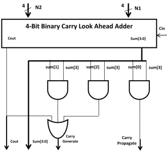
Figure 1 shows how the CG and CP signals of a digit are computed in our design. CG and CP signals are calculated from the SUM and Carry outputs of the first stage CLA adder using equations 1 and 2 respectively.
CP = Sum[3] . Sum[0] (1)
CG = Cout + Sum[3].Sum[2] + Sum[3].Sum[1] (2)
In the modified Adder-Analyzer block an additional input is given which in first stage is connected to Carry In(Cin) and for the remaining stages it is grounded. After having all CG and CP values the output carry of each digit can be calculated using carry network.
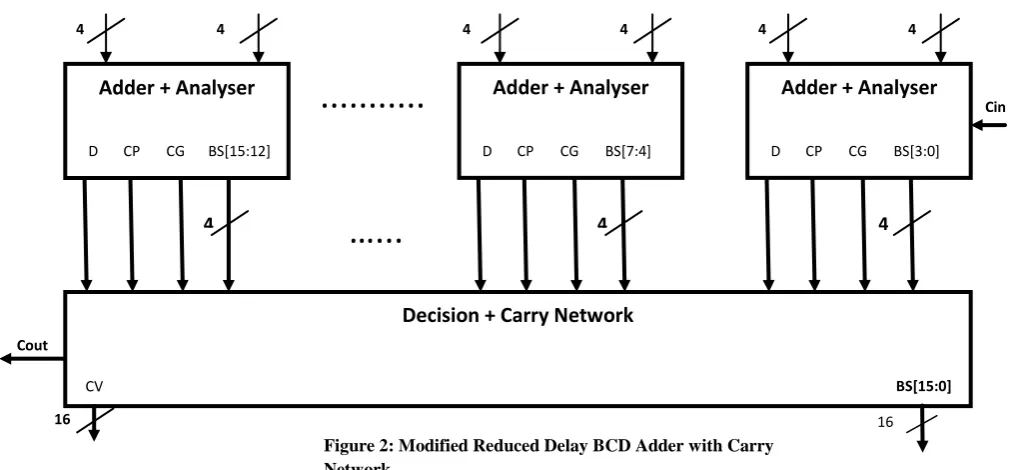
Carry Network can be a parallel prefix network which performs their operations in a constant time, irrespective of length of the inputs. In this paper Kogge-Stone prefix network is used as carry network as in [10]. The output of the carry network is used for correction of the output.
The integrated block diagram of Adder, Analyzer and Carry Network is shown in Figure 2. The carry for subsequent blocks are calculated in the carry network. The correction to the sum output of first stage adder is done by adding 0, 1, 6 or 7 to it. For each sum output, the present carry network output and previous carry network output determines the value to be added for correction. Unlike reduced delay BCD adder [10] in
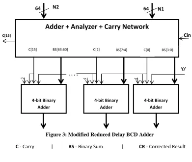
proposed adder Cin will not have a role in correcting the first stage output. Figure 3 shows the block diagram for modified reduced delay BCD adder which includes first stage CLA adder, Carry Network and Correction logic.
There are two major differences between reduced delay BCD adder and suggested one – First, for Adder and Analyzer block an extra input is given which is connected to Cin in the first stage and for subsequent stages this input is grounded. Second, Cin is no more used to correct the sum output of first stage adder.
4.
RESULTS AND DISCUSSIONS
A scalable n-bit modified reduced delay BCD adder and reduced delay are implemented in Verilog HDL and simulated with different corner case inputs. In case of reduced delay BCD adder, if the sum of first two digits is greater than 9 and Cin is zero the output correction from binary to BCD is found to be error some. Here two cases are mentioned which will explain the above scenario.
If the sum of the first digits in the both the operands is greater than 9 and Cin is one then the output is coming as expected, but if the Cin is zero, even though the sum value is greater than 9 the value added in the correction step is 4’b0000 instead of 4’b0110.
In the second case which is mentioned in Table 1, the first digits from the two inputs are 6 and 6 respectively and the sum output is ‘C’. Hence the correction value should have been 4’b0110 i.e., 6, which would have given the value 4’b0010 and a carry. But since Cin is zero the correction value is 4’b0000 which will lead to the erroneous output of ‘C’. Similar is the case with first scenario also.
In case of modified reduced delay BCD adder the above mentioned flaw is rectified by using Cin only in first stage adder and not in correction logic. The results for the modified reduced delay BCD adder can be observed in Table 2.
16
Cin
…...
...
.
Cout
Adder + Analyser
4 4
4 BS[3:0] CG
CP D
Adder + Analyser
4 4
4
Decision + Carry Network
BS[15:12] CG
CP D
CV
16
Adder + Analyser
4 4
4 BS[7:4] CG
CP D
BS[15:0]
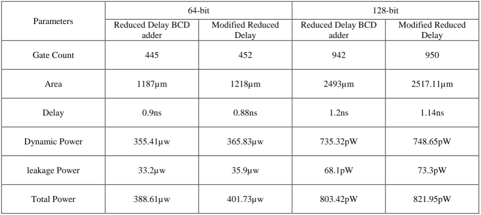
The reduced delay BCD adder [10] and the modified reduced delay BCD adder has been designed to support 64-bit and 128-bit decimal addition with BCD operands. All the adders are designed using Verilog HDL and the designs are optimized in synopsys design compiler using TSMC 65nm library and the results of 64-bit and 128 bit presented in table 3.
When Reduced Delay BCD (RBCD) adder is compared for delay with Modified Reduced Delay BCD adder (MRBCD), delay decreases by 2.2%. In terms of area, when Reduced Delay BCD (RBCD) adder is compared, Modified Reduced Delay BCD adder (MRBCD), area increases by 2.6%. Power calculations show that Reduced Delay BCD (RBCD) adder
shows an increase of 3.3% over Reduced Delay BCD adder (MRBCD).
When simulations are repeated for 128 bit design, the results are as in Table 3. In terms of delay, Modified Reduced Delay BCD adder (MRBCD), delay decreases by 5%. For area calculations, when Reduced Delay BCD (RBCD) adder is compared, Modified Reduced Delay BCD adder (MRBCD), area increases by 0.9%. Power calculations show, Modified Reduced Delay BCD adder (MRBCD), power increases by 2.3%.
Table 1 Simulation results of Reduced Delay BCD adder
Inputs Decimal Values
Carry In
(Cin) Sum Out
Carry Out (Cout)
Expected Sum Output
Expected Carry Out (Cout)
A 9999
0 9082 1 9098 1
B 9099
A 9999
1 9099 1 9099 1
B 9099
A 6626 0 209C 1 2102 1
C[15]
64
64
‘0’
. . . .
‘0’
‘0’
Cin
‘0 ’
N1
N2
Adder + Analyzer + Carry Network
4-bit Binary Adder
CR [63:60]
4-bit Binary Adder
CR [7:4]
4-bit Binary Adder
CR [3:0]
C
- Carry
|
BS
- Binary Sum
|
CR
- Corrected Result
BS[3:0} BS[7:4]BS[63:60] C[2] C[0]
C[15]
B 5476
A 6626
1 2103 1 2103 1
B 5476
Table 2 Simulation results of Modified reduced delay BCD adder.
Inputs Decimal Values
Carry In
(Cin) Sum Out
Carry Out (Cout)
Expected Sum Output
Expected Carry Out (Cout)
A 9999
0 9098 1 9098 1
B 9099
A 9999
1 9099 1 9099 1
B 9099
A 6626
0 2102 1 2102 1
B 5476
A 6626
1 2103 1 2103 1
B 5476
Table 3 Synthesis results of Reduced Delay BCD adder and Modified Reduced delay BCD adder for 64-bit & 128-bit
Parameters
64-bit 128-bit
Reduced Delay BCD adder
Modified Reduced Delay
Reduced Delay BCD adder
Modified Reduced Delay
Gate Count 445 452 942 950
Area 1187µm 1218µm 2493µm 2517.11µm
Delay 0.9ns 0.88ns 1.2ns 1.14ns
Dynamic Power 355.41µw 365.83µw 735.32pW 748.65pW
leakage Power 33.2µw 35.9µw 68.1pW 73.3pW
Total Power 388.61µw 401.73µw 803.42pW 821.95pW
5.
CONCLUSION
A details study of reduced delay BCD adder was done and few functional errors were identified when simulated with corner cases. A modified reduced delay BCD adder has been proposed by bringing in few changes in the normal reduced delay BCD adder. The proposed design can handle all the corner cases where the previous design failed.
6.
REFERENCES
[1] W Buchholz Fingers or Fists? (The Choice of Decimal or Binary Representation). Communications of the ACM, vol.2, issue 12, pg 3–11, December 1959.
[3] M. F. Cowlishaw. Decimal Floating-Point: Algorism for Computers. In Proceedings of 16th IEEE Symposium onComputer Arithmetic, pages 104–111, June 2003 [4] M. M. Mano. Digital Design, pages 129–131. Prentice
Hall, third edition, 2002.
[5] I. S. Hwang. High Speed Binary and Decimal Arithmetic Unit. United States Patent, (4,866,656), September 1989. [6] B. Shirazi, D. Y. Y. Young, and C. N. Zhang. RBCD: Redundant Binary Coded Decimal Adder. In IEEE Proceedings, Part E, No. 2, volume 136, pages 156–160, March 1989.
[7] M. S. Schmookler and A.W.Weinberger. High Speed Decimal Addition. IEEE Transactions on Computers, C-20:862– 867, Aug. 1971.
[8] J. D. Thompson, N. Karra, and M. J. SchulteB. A 64-Bit Decimal Floating-Point Adder. In Proceedings of the IEEE Computer Society Annual Symposium on VLSI, pages 297– 298, February 2004.
[9] P. M. Kogge and H. S. Stone. A Parallel Algorithm for The Efficient Solution of a General Class of Recurrence Equations. IEEE Trans. on Computers, C-22(8), Aug. 1973.