© 2005 - 2014 JATIT & LLS. All rights reserved.
ISSN: 1992-8645 www.jatit.org E-ISSN: 1817-3195
HARMONIC CURRENT SUPPRESSION BY SHUNT ACTIVE
POWER FILTER USING FUZZY LOGIC CONTROLLER
1AZIZ BOUKADOUM, 2 TAHAR BAHI
1 Department of Electrical Engineering, University of Tebessa, Algeria 2Department of Electrical Engineering, University of Annaba, Algeria
E-mail: 1 [email protected], 2 [email protected]
ABSTRACT
Harmonic current is known to be source of several problems in electrical power system due to the intensive use of the non-linear loads such as AC/DC converters. The harmonic current and reactive power consumed cause poor power factor and distort the supply voltage at the common coupling point or customer service point. Passive filters have been used as a solution to solve harmonic current problems, but they present several disadvantages, such as resonance affecting the stability of the system. The alternative solution, are an active power filters (APfs) that provides an effective solution for harmonics suppression and reactive power compensation. The performance and effectiveness of the active power filters depends upon different control strategies. In order to eliminate harmonics current generated in the power supply system by three-phase full-bridge diode rectifier converter and to provide a unitary power factor in the system. This paper present a novel compensation method based on fuzzy logic controller for shunt active power filter (SAPF). The principle of the Instantaneous Reactive Power Algorithm is applied for extracting the reference compensating currents of the shunt power converter. The fuzzy logic controller (FLC) is applied to regulate the DC capacitor voltage in order to improve the dynamic of the active power filter and to ensure sinusoidal main supply currents, confirmed to the international standards recommendation of IEEE 519 on harmonics levels. The simulation results are presented and interpreted.
Keywords: Harmonic, Fuzzy logic controller, Hysteresis, Shunt active power filter, Power quality.
1. INTRODUCTION
The non-linear loads such as power electronic equipments produce harmonics current. The harmonic current and reactive power cause poor power factor and distort the supply voltage at the common coupling point or customer service point [1],[2],[3]. The international standards recommendation and requirements for harmonic control in electrical power systems imposed some harmonic limits [4],[5]. In order to solve this problem, Firstly, different configuration are proposed of passive filters have been used to eliminate harmonics current and to compensate reactive power by increasing the power factor. But these filters have the disadvantages of large size; they are ineffective due to their inability to adapt to network parameters characteristic variation, problem of resonance, and deterioration of parameters [6]. The development of power electronic equipment, since the 1970s environment, active power filters (APFs) was been one of the most competitive modern solutions to suppressing harmonic pollution [7], enhance power quality, and insure the better power distribution system.
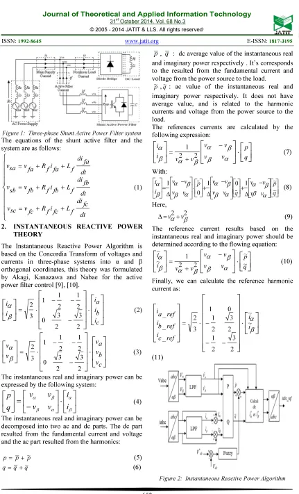
Figure 1: Three-phase Shunt Active Power Filter system
The equations of the shunt active filter and the system are as follows:
+ + = + + = + + = dt fc di f L fc i f R fc v sc v dt fb di f L fb i f R fb v sb v dt fa di f L fa i f R fa v sa v (1)2. INSTANTANEOUS REACTIVE POWER THEORY
The Instantaneous Reactive Power Algorithm is based on the Concordia Transform of voltages and currents in three-phase systems into α and β orthogonal coordinates, this theory was formulated by Akagi, Kanazawa and Nabae for the active power filter control [9], [10].
⋅ − − − ⋅ = c i b i a i i i 2 3 2 3 0 2 1 2 1 1 3 2 β α (2)
⋅ − − − ⋅ = c v b v a v v v 2 3 2 3 0 2 1 2 1 1 3 2 β α (3)The instantaneous real and imaginary power can be expressed by the following system:
⋅
−
=
β α α β β αi
i
v
v
v
v
q
p
(4)The instantaneous real and imaginary power can be decomposed into two ac and dc parts. The dc part resulted from the fundamental current and voltage and the ac part resulted from the harmonics:
p p
p= + ~ (5) q
q
q= +~ (6)
p, q : dc average value of the instantaneous real
and imaginary power respectively . It’s corresponds to the resulted from the fundamental current and voltage from the power source to the load.
p
~,q~: ac value of the instantaneous real and
imaginary power respectively. It does not have average value, and is related to the harmonic currents and voltage from the power source to the load.
The references currents are calculated by the following expression:
⋅ − + = q p v v v v v v i i α β β α β α β α 2 2 1 (7) With:
− ∆ + − ∆ + ⋅ − ∆ = q p v v v v q v v v v p v v v v i i ~ ~ . 1 0 . 1 0 1 α β β α α β β α α β β α β α (8) Here,∆=vα2+v2β (9)
The reference current results based on the instantaneous real and imaginary power should be determined according to the flowing equation:
⋅ − + = q p v v v v v v i i ~ ~ 2 2 1 ~ ~ α β β α β α β α (10)Finally, we can calculate the reference harmonic current as:
⋅ − − − ⋅ = β α i i ref c i ref b i ref a i ~ ~ 2 3 2 1 2 3 2 1 0 1 3 2 _ _ _ (11) [image:2.595.89.291.110.243.2]© 2005 - 2014 JATIT & LLS. All rights reserved.
ISSN: 1992-8645 www.jatit.org E-ISSN: 1817-3195
3. CONTROL OF DC BUS VOLTAGE
The advantage control of DC capacitor voltage source of shunt active power filter arises suitable transit of supply power necessary added to power active fluctuate. The storage capacity C absorbs the power fluctuations caused by the compensation of the reactive power. In the normal condition, the real power supplied by the source should be equal to that required by the load plus a low power to compensate the losses in the active filter [11]. Thus, the DC capacitor voltage can be kept equal to its reference. In abnormal condition such as presence of current harmonics, when the load changes, the equilibrium of power between the source and the load will be disrupted. In this case, the real power is compensated by the DC capacitor voltage. The changes of DC capacitor voltage from its reference most is regulate.
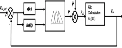
A. Fuzzy logic controller
[image:3.595.92.290.445.523.2]A fuzzy logic controller is based on a collection of control rules governed by the compositional rule of inference applied to maintain the constant voltage across the capacitor by minimizing the error between the capacitor voltage and its reference voltage [12],[13]. Figure. 3 shows the block diagram of fuzzy logic controller.
Figure 3: Control of dc bus voltage
A fuzzy logic controller (FLC) converts is advanced control strategy [14], the based fuzzy rules are constructed by expert experience or knowledge database. In the input of (FLC), the error e (k ) and the Change of error ∆e ( k ) have been placed of the angular velocity to be the input variables of the fuzzy logic controller. Then the output variable of (FLC) the fuzzy logic controller is presented by the control voltage µ (k), the type of fuzzy inference engine used is Mamdani. The linguistic input variables are defined as (N, Z, P,) which, negative, zero, and positive respectively. In The output the linguistic variables are defined as (PB, PM, PS) which, positive big, positive mean and, positive small zero respectively. The fuzzy rules are summarized in Table 1.
Table 1: Rule base table
∆e(k)
e(k) NB NS Z PS PB
N PB PS PS Z NB
Z PB PS Z NS NB
P PB Z NS NS NB
The instantaneous active power absorbed by the shunt active power filter can be expressed as:
2 )
2 1 (
dc v dc C dt
d dc
p = ⋅ (12)
For few variation value of DC capacitor voltage around its reference, we have:
dt dc v d dc v dc C dc
p ( )
2 1 *
⋅ ⋅ ⋅
= (13)
Applying Laplace transform:
s dc C dc v
s dc p s
dc v
⋅ ⋅ ⋅ =
*
) ( 2 )
( (14)
The instantaneous error e(k) between vdcand its
reference *
dc
v is given by :
dc v dc v k
e( )= * − (16)
The change of the error can be calculated by:
) 1 ( ) ( )
( = − −
∆e k e k e k (17)
The output of the fuzzy logic controller system is the change of the maximum currentµ(k), the
Product block outputs P is the result of multiplying of the error dc voltage e(k)and the
output maximum current of FLC, obtained according to following equation:
)
( ) ( )(k k e k
P =µ ⋅∆ (18)
4. HYSTERESIS CURRENT CONTROL
Hysteresis band current control does not need any information about the system parameters but has the disadvantage of uncontrolled switching frequency. The instantaneous value of the error can be calculated by subtracting from the identify reference harmonic currents (iref) obtained by using
bloc diagram of (p–q theory) (figure. 2.) And the injection harmonic currents (iinj), subtraction
between (iinj) and (iref) , introduced in hysteresis
Figure 4: Hysteresis band current control
5. SIMULATIONRESULTS
Simulations test is performed to confirm the validity of the proposed system. The shunt active power filter was examined through simulations Matlab/Simulink. All spectrum analysis harmonic figures are below the levels imposed by international standards recommendation IEEE 519-1992, in terms of total distortion harmonic (THD). The parameters of the simulated system are shown in Table 2.
Table 2: Parameters System
Figure 5 shows the main supply current distorted due to the presence of harmonics.
Figure 5: Main supply current (uncompensated)
In this case, the spectrum harmonics analysis, where the THD is 26.52%, that is far the limit of the harmonic standard, shown as Figure. 6.
Figure 6: Spectrum Harmonics (uncompensated)
The reference compensation current harmonic and injection active filter currents are shows by Figure.
7. The spectrum harmonics analysis can be seen in Figure 8, which contains the 5th, 7th, 11th, 13th, etc…
Figure 7: Reference and injection currents harmonic
Figure 8: Spectrum of compensate current harmonics
The filtering result can be seen in Figs. 9 and 10. The main supply current is sinusoidal and the THD decreases to 0.84 % before harmonic compensation that is within the limit of the harmonic standard.
Figure 9: Main supply current (compensated)
Figure 10: Spectrum Harmonics (compensated)
To verified that they are in phase. Figure 11, a, b shows the main supply current and voltage waveforms.
RMS supply phase voltage source 50 V, 50Hz
source impedance R=0.1 Ω, L=0.5mH
© 2005 - 2014 JATIT & LLS. All rights reserved.
ISSN: 1992-8645 www.jatit.org E-ISSN: 1817-3195
a) Before Compensation
[image:5.595.96.361.100.386.2]b) After Compensation Figure 11: Supply current and voltage
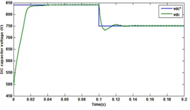
The figure 12 shows the DC capacitor voltage; we can see that its value follows up its reference at 840V. We have changed the reference value at t= 0.1s at 750V.
Figure 12: The DC capacitor voltage regulation
Figure 13 presents the evolution of the instantaneous three-phase active and undesirable consumable reactive power without SAPF.
Figure 13: Instantaneous active and reactive power (without SAPF)
Figures 14 and 15 present the waveform of the instantaneous active and reactive power and power factor correction with the use of SAPF. We can seen, that the power active and reactive and power factor also improved.
[image:5.595.307.504.239.441.2]Figure 14: Instantaneous active and reactive power after compensation (with SAPF)
Figure 15: Power factor correction (unit factor)
In all studied cases we observe that the DC link follows its reference and the line current is sinusoidal with a unit factor, this means that the control is robust.
5. CONCLUSION
[image:5.595.90.284.434.546.2] [image:5.595.91.282.605.708.2]REFERENCES:
[1.] A. Semmah, A. Massoum, Habib Hamdaoui, Patrice WIRA ‘’Comparative Study of PI and Fuzzy DC Voltage Control for a DPC- PWM Rectifier‘’, Przegląd Elektrotechniczny (Electrical Review), ISSN 0033-2097, R. 87 NR 10/2011. pp. 355-359.
[2.] A. kessal, L. rahmani, M. mostefai ‘’Power factor correction based on fuzzy logic controller with fixed switching frequency‘’,
Electronics and electrical engineering, 2012. no. 2(118) Elektronika ir Elektrotechnika.
[3.] Yu Chen and Bo Fu Qionglin Li “Fuzzy Logic Based Automodulation of Parameters PI Control for Active Power Filter”, World Congress on Intelligent Control and Automation June 25 - 27, 2008.
[4.] Karuppanan P and Kamala Kanta Mahapatra ‘’PI, PID and Fuzzy logic controller for Reactive Power and Harmonic Compensation‘’, ACEEE Int. J. on Electrical and Power Engineering, Vol. 01, No. 03, Dec 2010.
[5.] IEEE Standard, ‘’IEEE recommended practices
and requirements for harmonic control in electrical power systems’’, IEEE Std 519-1992, 12 April.1993.
[6.] T. Mahalekshmi ‘’Current Harmonic Compensation and Power Factor Improvement by Hybrid Shunt Active Power Filter‘’,
International Journal of Computer Applications (0975 – 8887) Volume 4 – No.3, July 2010.
[7.] L. Gyugyi and E. Strycula, “Active AC power
filters”, in Conf. Rec. IEEE-IAS Annu. Meeting, 1976, pp. 529–535.
[8.] H. Sasaki & T. Machida, “A new method to eliminate AC harmonic currents by magnetic flux compensation-considerations on basic design”, IEEE Trans. Power Appl. Syst., vol. PAS-90, No. 5, pp. 2009–2019, Jan. 1971.
[9.] F. Z. Peng, H. Akagi, and A. Nabae,
‘’Compensation characteristics of the combined system of shunt passive and series active filters’’, IEEE'Trans. Industry Applications, Vol. 29, No.1, pp. 144-152,1993.
[10.]H. Akagi, Y. Kanazawa and A. Nabae
’’Generalized theory of the instantaneous reactive power in three-phase circuits’’,
Proceeding International Power Electronics Conference.Tokyo, Japan, pp. 1375-1386, (1983).
[11.]P. Rathika and Dr. D. Devaraj ‘’Fuzzy Logic –
Based Approach for Adaptive Hysteresis Band and Dc Voltage Control in Shunt Active Filter’’, International Journal of Computer and Electrical Engineering, Vol. 2, No. 3, June, 2010, 1793-8163.
[12.]Saidah, M. Hery Purnomo, M. Ashari
‘’Advanced control of active rectifier using switch function and fuzzy logic for nonlinear behaviour compensation‘’, Journal of Theoretical and Applied Information Technology 30th June 2012. Vol. 40 No.2.
[13.] S. Chennai and M. T. Benchouia ‘’Intelligent
Controllers for Shunt Active Filter to Compensate Current Harmonics Based on SRF and SCR Control‘’, Strategies International Journal on Electrical Engineerin g and Informatics,Volume 3, Number 3, 2011.
[14.]A. Boukadoum, T. Bahi, A. Bouguerne, Y.