Abstract—In this paper, a robust control system with the fuzzy sliding mode controller and the additional compensator is presented. The additional compensator relaying on the sliding-mode theory is used to improve the dynamical characteristics of the drive system. Sliding mode control method is studied for controlling DC motor because of its robustness against model uncertainties and external disturbances, and also its ability in controlling nonlinear and MIMO systems. In this method, using high control gain to overcome uncertainties lead to occur chattering phenomena in control law which can excite unmodeled dynamics and maybe harm the plant. Different approaches, such as intelligent methods, are used to abate these drawbacks.. In order to enhancement the sliding mode controller performance, we have used fuzzy logic. For this purpose, we have used a PID outer loop in the control law then the gains of the sliding term and PID term are tuned on-line by a fuzzy system, so the chattering is avoided and response of the system is improved against external load torque here. Presented simulation results confirm the above claims and demonstrate the performance improvement in this case.
Index Terms— DC motor, fuzzy logic, PID, sliding mode.
I. INTRODUCTION
The proportional-integral-derivative (PID) controller is widely used in many control applications because of its simplicity and effectiveness. Though the use of PID control has been a long history in the field of control engineering, the three controller gain parameters, proportional gain KP,
integral gain KI, and derivative gain KD, are usually fixed. The disadvantage of PID controller is poor capability of dealing with system uncertainty, i.e., parameter variations and external disturbance. Robustness has gained more and more attention.
In recent years, there has been extensive interest in self-tuning these three controller gains. For examples, the PID self-tuning methods based on the relay feedback technique were presented for a class of systems [1, 2]. An adaptive PID
Manuscript received January 10, 2009.
Mohsen Fallahi is with the Department of Mechatronics Engineering, Semnan University, Semnan, Iran, (phone:0989173184529; e-mail:[email protected])
Sasan Azadi is with the Department of Electrical Engineering, Semnan University, Semnan, Iran, (e-mail: [email protected], [email protected]).
control PID control tuning was proposed to cope with the control problem for a class of uncertain chaotic systems with external disturbance [3]. A genetic algorithm was used to find the optimum tuning parameters of the PID controller by taking integral absolute error as fitting function [4]. Sliding mode control (SMC) is one of the popular strategies to deal with uncertain control systems [5-7]. The main feature of SMC is the robustness against parameter variations and external disturbances. Various applications of SMC have been conducted, such as robotic manipulators, aircrafts, DC motors, chaotic systems, and so on [8-10].
The sliding mode control is robust to plant uncertainties and insensitive to external disturbances. It is widely used to obtain good dynamic performance of controlled systems. However, the chattering phenomena due to the finite speed of the switching devices can affect the system behavior significantly. Additionally, the sliding control requires the knowledge of mathematical model of the system with bounded uncertainties. Reduced chattering may be achieved without sacrificing robust performance by combining the attractive features of fuzzy control with SMC. Fuzzy logic is a potent tool for controlling ill-defined or parameter-variant plants. By generalizing fuzzy rules, a fuzzy logic controller can cope well with severe uncertainties. Fuzzy schemes with explicit expressions for tuning can avoid the heavy computational burden [11-14].
DC motor are generally controlled by conventional Proportional – Integral – Derivative (PID) controllers, since they designed easily, have low cost, inexpensive maintenance and effectiveness. It is necessary to know system’s mathematical model or to make some experiments for tuning PID parameters. However, it has been known that conventional PID controllers generally do not work well for non-linear systems, and particularly complex and vague systems that have no precise mathematical models. To overcome these difficulties, various types of modified conventional PID controllers such as auto-tuning and adaptive PID controllers were developed lately. Also Fuzzy Logic Controller (FLC) can be used for this kind of problems. When compared to the conventional controller, the main advantage of fuzzy logic is that no mathematical modeling is required [15-17]
In this paper the combined solution we have proposed and designed a robust controller. We have used a PID outer loop in the control law then the gains of the sliding term and PID
Robust Control of DC Motor Using Fuzzy
term are tuned on-line by a fuzzy system.
II. MODEL OF A DC MOTOR
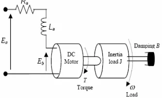
[image:2.612.96.263.160.261.2]DC motors are widely used in industrial and domestic equipment. The control of the position of a motor with high accuracy is required. The electric circuit of the armature and the free body diagram of the rotor are shown in fig. 1
Fig. 1: The structure of a DC motor
A desired speed may be tracked when a desired shaft position is also required. In fact, a single controller may be required to control both the position and the speed. The reference signal determines the desired position and/or speed. The controller is selected so that the error between the system output and reference signal eventually tends to its minimum value, ideally zero. There are various DC motor types. Depending on type, a DC motor may be controlled by varying the input voltage whilst another motor only by changing the current input.
In this paper a DC motor is controlled via the input voltage. The control design and theory for controlling a DC motor via current is nearly the same. For simplicity, a constant value as a reference signal is injected to the system to obtain a desired position. However, the method works successfully for any reference signal, particularly for any stepwise time-continuous function. This signal may be a periodic signal or any signal to get a desired shaft position, i.e. a desired angle between 0 and 360 degrees from a virtual horizontal line.
The dynamics of a DC motor may be expressed as:
a a a a a
t
E
dt
dI
L
I
R
V
=
+
+
(1)l
T
B
dt
d
J
T
=
ω
+
ω
−
(2)a T
I
K
T
=
(3)ω
a
a
K
E
=
(4)φ
ω
=
dt
d
(5) With the following physical parameters:
Ea: The input terminal voltage (source), (v); Eb: The back emf, (v);
Ra: The armature resistance, (ohm);
Ia: The armature current (Amp); La: The armature inductance, (H);
J: The moment inertial of the motor rotor and load, (Kg.m2/s2);
T: The motor torque, (Nm)
ω
: The speed of the shaft and the load (angular velocity),(Rad/s);
φ
: The shaft position, (rad);B: The damping ratio of the mechanical system, (Nms); T k: The torque factor constant, (Nm/Amp);
B k: The motor constant (v-s/rad).
[image:2.612.325.543.228.361.2]Block diagram of a DC motor is shown in fig. 2
Fig. 2: The block diagram of a DC motor
III. SLIDING MODE CONTROLLER
A Sliding Mode Controller is a Variable Structure Controller (VSC). Basically, a VSC includes several different continuous functions that can map plant state to a control. Surface and the switching among different functions are determined by plant state that is represented by a switching function. Without lost of generality, consider the design of a sliding mode controller for the following second order system: Here u (t) is the input to the system:
eq
s
u
u
u
=
+
(6) Whereu
s=
−
k
.
sat
(
s
/
φ
)
and constant factorφ
defines the thickness of the boundary layer.sat
(
s
/
φ
)
Is a saturation function that is defined as:>
≤
=
1
)
/
sgn(
1
)
/
(
φ
φ
φ
φ
φ
s
if
s
s
if
s
s
sat
(7)Fig3: Switching surface in the phase plane
The control strategy adopted here will guarantee the system trajectories move toward and stay on the sliding surface s 0 from any initial condition if the following condition meets:
s
s
s
≤
−
η
.
(8) Where
η
is a positive constant that guarantees the system trajectories hit the sliding surface in finite time .Using a sign function often causes chattering in practice. One solution is to introduce a boundary layer around the switch surface.This controller is actually a continuous approximation of the ideal relay control. The consequence of this control scheme is that invariance of sliding mode control is lost. The system robustness is a function of the width of the boundary layer.
The principle of designing sliding mode control law for arbitrary-order plants is to make the error and derivative of error of a variable is forced to zero. In the DC motor system the position error and its derivative are the selected coordinate variables those are forced to zero. Switching surface design consists of the construction of the switching function. The transient response of the system is determined by this switching surface if the sliding mode exists. First, the position error is introduced:
)
(
)
(
)
(
k
k
k
e
=
θ
ref−
θ
(9) Whereθ
ref(
k
)
andθ
(
k
)
are the respective responses of the desired reference track and actual rotor position, at the kthe sampling interval and e (k) is the position error. The sliding surface (s) is defined with the tracking error (e) and its integral (
edt
) and rate of change (.
e
).+
+
=
e
e
edt
s
1 2.
λ
λ
(10)Where
λ
1,
λ
20
are a strictly positive real constant. Thebasic control law of Sliding Mode Controller is given by: U=-ksgn(s) (11) Where K is a constant parameter, sign (·) is the sign
function and S is the switching function.
IV. DESIGN OF FUZZY PIDSLIDING MODE CONTROLLER
In this section, a fuzzy sliding surface is introduced to develop a sliding mode controller. Which the expression
)
/
(
.
sat
s
φ
k
−
is replaced by an inference fuzzy system for eliminate the chattering phenomenon.In addition, to improve the response of system against external load torque, the sliding mode controller designs with a PID out loop.
The designed fuzzy logic controller has two inputs and an output. The inputs are sliding surface (s) and the change of the sliding surface ( s. ) in a sample time, and output is the
fuzzy gain (
k
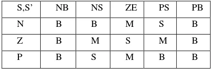
fuzz).The fuzzy controller consists of three stages: fuzzyfication, inference engine and defuzzyfication. Then, a 3*5 rule base was defined (Table 1) to develop the inference system. Both fuzzyfication and inference system were tuned experimentally. [image:3.612.326.546.391.464.2]The membership function of inputs variable are depicted in Fig. 3, 4 and the membership function of the output variable is depicted in Fig. 5
TABLE I: Fuzzy rule base
S,S’ NB NS ZE PS PB
N B B M S B
Z B M S M B
P B S M B B
Where NB=Negative big; NS: Negative Small; Z: Zero; PS: Positive Small; PB: Positive Big; M: Medium.
For example when S is (NS) and
.
s
is (P), sok
fuzz is Small(S).The sliding function is defined as:
+
+
=
e
e
edt
s
1 2.
λ
λ
(12) Whereλ
1,
λ
20
are a strictly positive real constant. The control law is defining as:)
sgn(
s
k
s
k
u
=
v+
(13) Wherek
vs
=
k
ve
+
k
ve
+
k
v 0tedt
.
λ
λ
andfuzz fuzz
v
v
N
k
k
Nk
k
=
,
=
[image:4.612.66.283.67.184.2]
Fig. 3: Membership functions for (s) normalized inputs
Fig. 4 Membership functions for (ds/dt) normalized inputs
Fig. 5Membership functions for (Kfuzz) normalized outputs
V. SIMULATIONRESULTS
In this section, the overall model of DC motor with sliding mode controller and fuzzy logic and PID is implemented in MATLAB/Simulink.
[image:4.612.323.570.134.304.2]The simulink model of the FSMC is shown in fig. 6 and the FPIDSMC is shown in fig. 7
Fig. 6: simulink block diagram of FSMC
Fig. 7: simulink block diagram of FPIDSMC
In order to test the robustness of the controllers against uncertainties and external disturbances and external load torque, we change the parameters of DC motor and use sine wave block with amplitude and frequency=2.
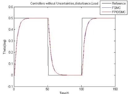
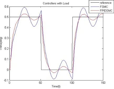
[image:4.612.65.282.222.337.2]Fig, 8 shows the controllers without Uncertainties, disturbances and external load torque, fig, 9 shows response of system against uncertainties in the system, fig, 10 shows the disturbance rejection of FPIDSMC and FSMC when the system operated under no load torque and fig. 11 shows the response of the system with a load disturbance torque.
[image:4.612.66.289.384.502.2] [image:4.612.340.547.460.612.2]Fig. 9: Simulated results comparison between the FPIDSMC and FSMC controller of DC motor with uncertainties
Fig. 10: Simulated results comparison between the FPIDSMC and FSMC controller of DC motor with external disturbances
Fig. 11: Simulated results comparison between the FPIDSMC and FSMC controller of DC motor with external load torque
VI. CONCLUSION
In this paper, a robust control system with the fuzzy sliding mode controller and the additional compensator is presented for a DC motor position control. According to the simulation results, the FPIDSMC and FSMC controllers can provide the properties of insensitivity and robustness to uncertainties and external disturbances, and response of the DC motor for FPIDSMC and FSMC controllers against uncertainties and external disturbance is the same. But the comparison between the position control of the DC motor by a FPIDSMC and a FSMC shows clearly that the FPIDSMC gives better performances than FSMC against external load torque. So proposed controller is a robust controller, and the chattering is avoided and response of the system is improved against external load torque.
REFERENCES
[1] A. Leva, “PID autotuning algorithm based on relay feedback,” IEE Porc-Control Theory Appl., vol. 140, 1993, pp. 328-337.
[2] Q. G. Wang, B. Zou, T. H. Lee, and Q. Bi, “Auto-tuning of multivariable PID controller from decentralized relay feedback,”
Automatica, vol. 33, 1997, pp. 319-330.
[3] W. D. Chang and J. J. Yan, “Adaptive robust PID controller design based on a sliding mode for uncertain chaotic systems,” Chaos Solitions & Fractals, vol. 26, 2005, pp. 167-175.
[4] A. Altinten, S. Erdogan, F. Alioglu, H. Hapoglu, and M. Alpbaz, “Application of adaptive PID with genetic algorithm to a polymerization reactor,” Chemical Eng. Comm., vol. 191, 2004, pp.1158-1172.
[5] J. Y. Hung, W. Gao, and J. C. Hung, “Variable structure control: a survey,” IEEE Trans. Ind. Electr., vol. 40, 1993, pp. 2-22.
[6] K. D. Young, V. I. Utkin, and Ü. Özgüner, “A control engineer's guide to sliding mode control,” IEEE Trans. Control Sys. Tech., vol. 7, 1999, pp. 328-342.
[7] A. S. I. Zinober, Variable Structure and Lyapnuov Control. Berlin: Springer-Verlag, 1994.
[8] Y. J. Huang and T. C. Kuo, “Robust position control of DC servomechanism with output measurement noise,” Electr. Eng., vol. 88, 2006, pp. 223-238.
[9] P. Guan, X. J. Liu, and J. Z. Liu, “Adaptive fuzzy sliding mode control for flexible satellite,” Engineering Appl. Arti Intelli., vol. 18, 2005, pp. 451-459.
[10] H. S. Choi, Y. H. Park, Y. S. Cho, and M. Lee, “Global sliding-mode control improved design for a brushless DC motor,” IEEE Control Systems Magazine, vol. 21, 2001, pp. 27-35.
[11] Koshkouei, A. J. and Zinober, A. S. I., sliding mode controller-observer design for SISO linear systems. Int. J. systems Science, 29, 1363-1373, 1998.
[12] Drakunov, S. V. and Utkin, V. I., Sliding mode control in dynamic systems. Int. J. Control, 55, 1029-1037, 1992.
[13] T.C. Manjunath," Design of Moving Sliding Surfaces in A Variable Structure Plant & Chattering Phenomena", International Journal of Electronics, Circuits and Systems Volume 1 Number 3,
[14] Mohammed Golam Sarwer, Md. Abdur Rafiq and B.C. Ghosh," Sliding Mode Speed Controller of a D.C Motor Drive", Journal of Electrical Engineering, The Institution of Engineers, Bangladesh ,Vol. EE 31, No. I & II, December 2004
[15] Ali J. Koshkouei and Keith J. Burnham," CONTROL OF DC MOTORS USING PROPORTIONAL INTEGRAL SLIDING MODE", Control Theory and Applications Centre, Coventry University, Coventry CV1 5FB, UK
[16] Bogumila Mrozek and Zbigniew Mrozek," Modelling and Fuzzy Control of DC Drive", 14-th European Simulation Multiconference ESM 2000, May 23-26, Ghent, pp186-190
[image:5.612.76.293.499.668.2]