Copyright to IJIRSET www.ijirset.com 44
An Efficient OFDMA Encoding and
Decoding Scheme Using MIMO
Architecture for Wireless Network
Applications
V.Naveen Kumar
1, Dr.T.Menakadevi
2, V.Anitha
3PG Scholar, Department of ECE, Adhiyamaan College of Engineering, Hosur, TN, India 1
Professor, Department of ECE, Adhiyamaan College of Engineering, Hosur, TN, India 2
Ph.D Scholar, Department of ECE, Adhiyamaan College of Engineering, Hosur, TN, India 3
ABSTRACT: OFDMA (Orthogonal Frequency Division Multiple Access) technique has been recently applied to wireless networks. CDMA (Code Division Multiple Access) is not suitable for designing a platform that requires computational power and flexiblility at the same time. The proposed encoding and decoding method helps to hold the performance and cost of OFDMA Networks. The proposed system reduces the area and power consumption comparing to the existing system. In transmitter module, source data from different sender are independently encoded with an orthogonal code of a standard basis and these coded data are mixed together by an XOR operation. Then, the sum of data can be transmitted to their destinations through the wireless infrastructure. In the receiver module, a sequence of chips is retrieved by taking an AND operation between the sum of data and the corresponding orthogonal code. After a simple accumulation of these chips, original data can be reconstructed. MIMO detection system based on multi-core principles where the computation nodes are interconnected using the Network On Chip (NOC) model.
I. INTRODUCTION
The Multi Input Multi Output (MIMO) technique has become a necessary ingredient in modem communication systems such as LTE/LTE-A and IEEE802.11n/ac [1], as it can improve the quality of wireless signal or data rate with the utilization of multiple antennas at the transmitter side either receiver side. MIMO technology is also widely used with Orthogonal Frequency Division Multiplexing (OFDM) modulation in contemporary wireless systems. Moreover, the system using large number of antennas, commonly known as the massive (or large-scale) MIMO system comes under the spotlight and draws interests both from theoretical and practical aspects[3].
Dr.T.Menakadevi et al., [4 & 5] has designed and implemented a Direct Digital Synthesizer using CORDIC approach, to increase the speed with minimum area requirement in FPGA. COordinate Rotation DIgital Computer (CORDIC) algorithm is an interesting technique for phase to sine amplitude conversion which provides fast and area efficient computations of sine and cosine functions. Anitha.V et al., [6] have designed VLSI Architecture of a Clock-gating Turbo Encoder for WSN applications. The proposed work is implemented using clock gating technique in order to reduce the power consumption. The architecture uses the fundamental Add Compare Select (ACS) operation. Due to the parallel processing operation of ACS blocks it has low processing steps, so that low transmission energy and less complexity about 71%.
Copyright to IJIRSET www.ijirset.com 45
dynamic and the system operates in various framework with different radio link conditions, quality or service requirements etc., there will be an increasing more flexible system configuration. Therefore, it is highly profitable to design and configurable.
MIMO detection system contains adequate computational power to support different modulation schemes and number of antennas, especially for the large number of antennas. Multi-core systems usually used dedicated point to point signal wires or shared buses to send communication data over the cores [11]. Such scheme has features of simplicity, easy to implement, and low-cost. However, multi-core systems with point to point interconnection scheme comes with a cost of lacking scalability and flexibility, especially when the number of cores increases and the amount of communication between the cores enlarges. As a result, it might not be suitable for designing a platform that requires computational power and flexibility at the same time.
To overcome this disadvantage, Network-on-chip has been proposed for data communication [12 & 13]. The NOC architecture consists of a number of Process Elements(PEs) connecting to a local Router(R) through a Network Interface Controller(NIC),where each Router is inter-connected to construct an on-chip network. Since different algorithms and applications can be realized using different numbers of PEs and different inter-connection topologies, the NOC structure has much better scalability and flexibility to support an application with versatile operation modes.
Since its debut, several works have been published designing particular applications on the NOC- based multi-core platform. To be specific, an optimized methodology for mapping embedded applications on NOC paradigm [14]. Realization of turbo decoder for wireless communications on the NOC-based multi-core systems are proposed by many authors [15]. This architecture is highly flexible and versatile to support various numbers of antennas and different modulation schemes. This paper is organized as follows. Reviews of the NOC-based multi-core system and detailed circuit architecture are given in Section 2 and Section 3. The proposed STBC Encoding/Decoding technique and Alamouti Scheme is presented in Section 4 and experimental results and discussion are illustrated in Section 5. Finally, this paper is concluded in Section 6.
II. NOC-BASED MULTI-CORE SYSTEM
In a multi-core system, the cores (or Processing Elements, PEs) need to communicate with each other or to the external controller. This is traditionally done via the bus or cross-bar switches. However, such structures are lacking of flexibility or scalability and thus are not suitable for modern System On Chip (SOC) platforms. The architecture of NOC in mesh topology is presented in Fig.1.
.
Fig.1 NOC architecture in Mesh topology
PE
0PE
1PE
2PE
3R R R R
PE
4PE
5PE
6PE
7R R R R
PE
8PE
9PE
1PE
1R R R R
PE
1PE
1PE
1PE
1Copyright to IJIRSET www.ijirset.com 46
For instance, the throughput of a NOC-based multi-core system can be easily increased by adding more PEs onto the network, while the complexity can be quickly decreased by removing the PEs out of the network.
III. DETAILED CIRCUIT ARCHITECTURES
The Processing Element (PE) is the core of the NOC structure. Through the inter-connection and interaction between the PEs, send them to the destination PE. When receiving packets from the source, the router examines the destination information and decides the next destination of the packets based on a specific routing algorithm. It describes simple XY routing algorithm, the router directs the packet to x -coordinate of destination first, followed by the y-coordinate.
In addition, the Network Interface Controller (NIC) is the agency between the PE and the router. The architecture of (a) the Detection Unit, (b) the sorter unit, and (c) the enumeration unit is presented in Fig.3.1. The packet transferred on network must go through NIC as it appends the needed network information with the packet. For example, the NIC adds data type and x-coordinate, y-coordinate when the
XY routing algorithm is used. Furthermore, the packet sent to the PE is also passed by the NIC where it removes the network information.
Fig.2 The architecture of (a) the Detection Unit, (b) the sorter unit, and (c) the enumeration unit
Copyright to IJIRSET www.ijirset.com 47
~
Enumeration unit, in which the architecture controls two multiplexers based on the employed modulation scheme to select the best two symbols according to the result of comparators. The computed PEDs will then be sent to the sorter to determine the two or three best combinations.
Head flit
Body flit
Tail flit
Fig.3 The typical pipelined operating for the router.
The body ‘flit’ and tail ‘flit’ all follow the route of head ‘flit’ and thus RU and AU keep their original state when receiving body ‘flit’ or tail’ flit’. Therefore body ’flit’ and tail ‘flit’ has two stall stages. Moreover, the information is carried by each type of the packets. The typical pipelined operating for the router is presented in above Fig.3.
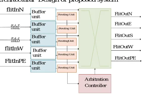
It is comprised of Buffer Units (BUs), Routing Units (RUs), Arbitration Controller (ACs), and Crossbar with five input/output ports representing, north, east, south, west, and local PE respectively. In Fig 3, the typical pipelined operating for the router is presented. In this structure, five RUs are running in parallel and each of them is responsible for one input port, whereas the BU is a First In First Out (FIFO) buffer with size equal to one flit for the wormhole switching. All flits coming from other routers first go to the buffer waiting to be routed.
This router implements a simple XY routing algorithm, where the RU routes the packet to x -coordinate of destination first, followed by the y-coordinate. Furthermore, the AC consists of five arbiters where each of them is responsible for one output port. In Fig.3, architectural overview for a typical router is presented. Once received a request from one or more RUs for using the output port, the arbiter only grants one request and controls crossbar to connect corresponding direction BU to the output port.
Architectural Design of proposed system
Arbitration Controller FlitOutN FlitOutE FlitOutS FlitOutW FlitOutPE flitInN Routing Unit Buffer unit itRouting Unit Buffer unit RoutingUnit Buffer unit Routing Unit Buffer unit Routing Unit Buffer unit flitInW FlitInPE
Fig.4 Architectural overview for a typical router.
BU RU AC Crossb
ar
BU Stall Stall Crossb
ar
BU Stall Stall Crossba
Copyright to IJIRSET www.ijirset.com 48
Fig.5 Proposed NOC architecture for MIMO-OFDM system
In this case, every 16 PEs are constructed as a cluster for processing one subcarrier. The number of subcarriers that can be processed at the same time depends on the number of clusters (and thus the number of PEs) in the system. In other words, the processing throughput of the entire system is related to the number of PEs in this multi-core system and leads to a design trade-off. More PEs can be instantiated when supporting a high-throughput application is desired, while less PEs are deployed when low area complexity and low power consumption are the major design goals. Proposed NOC architecture for MIMO-OFDM system is presented in above Fig.5.
In addition, a number of tree searching approaches have been proposed for realizing the near optimal MIMO detector. It is worth further researching on how to design and implement the NOC-based MIMO detector system.
IV. STBC ENCODING/DECODING
Space-time block codes (STBC) are a generalized form of Alamouti method, but have the same key property. These codes are orthogonal and can achieves full transmit diversity identify by the more number of transmit antennas. In further words, space-time block codes are a composite method of Alamouti space-time code, where the encoding and decoding method are the same as there in the Alamouti space-time code on both the transmitter and receiver sides.
At the receiver side, the signals received are first unify and then send to the maximal likelihood detector where the determination rules are executed. Space-time block codes were produce to carry out the maximum diversity order for the given more number of transmit and receive antennas subject to the control of having a simple linear decoding method.
Copyright to IJIRSET www.ijirset.com 49
pure training-based method to decrease the bandwidth efficiency considerably due to the use of a long training alignment which is certainly needed in order to reliable MIMO channel evaluate. Because of the computation complexity of blind and semi blind schemes, so many wireless communication devices still use pilot alignment to evaluate the channel parameters at the receiver side.
1. Alamouti Scheme
Alamouti strategy is the basic of the Space Time Coding method. The mathematical expression of this method containing two transmitter and one receiver antennas is also describe here. In this method, a two divide transmit diversity method is execute. Using two transmit antennas and one receive antenna, this method gives the same diversity arrangement as Maximal Ratio Receiver Combining (MRRC) with one transmit antenna and two receive antennas. This method may be generalized in to two transmitter and one receiver antennas to concede a diversity order of 2M. At the transmitter side, block of two symbols is accepted from the source data and send to the modulator.
After that, Alamouti space time encoder accepts the two modulated symbols, in this sample called s1 and s2 produces encoding matrix S where the symbols s1 and s2 are denotes to two transmitter antennas in two transmit time slots.
2. STBC Encoding/Decoding method
The encoder and decoder block diagram of the Alamouti method system is given in Fig 6. Here the data to be transmitted is modulated and fed to the space time encoder. The space time encoder consists of two transmit antennas as part of the multiple input multiple output (MIMO) technology. So here the data is transmitted through two separate antennas. Each transmitting and the receiving antenna pair has a channel, represented by different channel coefficients. These channel coefficients play a major role in the design of the system. As the total number of antennas multiplies at both the sides of the channel, hence complexity of the system also increases drastically.
Fig.6 Block Diagram of OFDMA Transmitter and Receiver
Copyright to IJIRSET www.ijirset.com 50
S[n] is a serial stream of binary digits. By inverse multiplexing, these are first de-multiplexed in to N parallel streams, and each one mapped to a (possibly complex) symbol stream using some modulation constellation (QAM, PSK, etc.). Note that the constellations may be different, so some streams may carry a higher bit-rate than others as given in Fig 6. From equation (1) and (2) the first and the second time slots of the received signals are analysed.
Fig.7 Block Diagram of OFDMA Encoding
In the first time slot, the received signal is,
………. (1)
In the second time slot, the received signal is,
………... (2)
V. RESULTS AND DISCUSSION
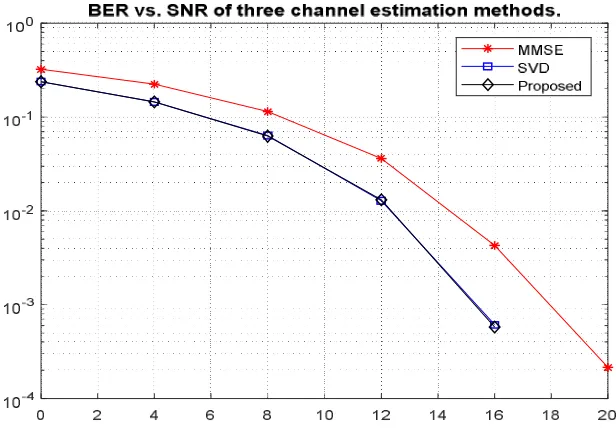
Alamouti space time code is an orthogonal method that can carry out the full transmit diversity of Nt = 2. The bit-error-rate (BER) versus signal to noise ratio (Eb/No (dB)) shows for Alamouti transmit diversity method on
Copyright to IJIRSET www.ijirset.com 51
Fig.8 Response of BER Vs SNR
Table 1 describes, Eb/N0 must be used with care on interference limited channels since additive white
noise (with constant noise density N0) is assumed, and interference is not always noise-like. In spread
spectrum systems the interference is sufficiently noise-like that it can be represented as I0 and added to the
thermal noise N0 to produce the overall ratio Eb/ (N0 + I0).
Copyright to IJIRSET www.ijirset.com 52
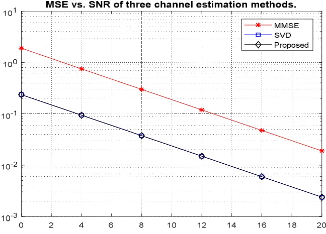
Fig.9 Response of MSE Vs SNR of three channel estimation methods
In Fig.9 it explains the response of MSE Vs SNR of three channel estimation methods. The performance of these two methods is compared by mathematical analysis and by simulation measuring Bit Error Rate (BER) and Mean Square Error (MSE) versus Signal to Noise Ratio (SNR).This result shows that, at higher SNR, the MMSE algorithm outperforms for both BER and SNR.
Table 2: MSE (Mean Square Error) Vs SNR (Signal to Noise Ratio)
Table 2 describes, increasing the values of MSE and SNR, partially decreasing Singular Value Decomposition (SVD) values (i.e.,) compared to MMSE, proposed system gives a good results and less power consumption.
VI. CONCLUSION
Copyright to IJIRSET www.ijirset.com 53
considered. In this case, the proposed system achieves about 65% accuracy. From the results it is noted that the Signal to Noise Ratio (SNR) and Bit Error Rate (BER) is reduced up to 4db and 0.001 respectively. So the proposed algorithm tends to decide which modulation scheme and the combination of antennas is to be used by the communication link. The better BER curve is achieved by this system which uses more number of antennas at both sides of the communication link. This is due to the fact that as the number of receiver antennas increases, the diversity of the system will increase. Finally as a future expansion of this paper, it is possible to introduce different modulation schemes to increase the data rates. Also we can increase the number of antennas at both transmitter and receiver without introducing any interference in between the antennas.
REFERENCES
[1]E.G. Larsson, F. Tufvesson, O. Edfors, T.L. Marzetta, “Massive MIMO for nextgeneration wireless systems”, IEEE Commun. Mag. 52 (2)186–195, 2014.
[2]A.Burg, M.Borgmann, M.Wenk, M.Zellweger, W.Fichtner, H.Bolcskei, “ VLSI implementation of MIMO detection using the sphere decoding algorithm”, IEEEJ. Solid State Circuits 40 1566–1577, 2005.
[3]T.-H.Kim, I.-C.Park, “Small-area and low-energy K-best MI MO detector using relaxed tree expansion and early forwarding”, IEEETrans.Circuits Syst.I: Regul. Pap. 57 (10) 2753–2761, 2010.
[4]T.Menakadevi and M.Madheswaran, “Direct Digital Synthesizer using Pipelined CORDIC Algorithm for Software Defined Radio”, International Journal of Science and Technology, Volume 2, June 2012.
[5] M. Madheswaran and T. Menakadevi, “An Improved Direct Digital Synthesizer Using Hybrid Wave Pipelining and CORDIC algorithm for Software Defined Radio”, Circuits, Systems, and Signal Processing, June 2013.
[6]Anitha.V and Dr.T.Menakadevi, “VLSI Architecture of a Clock-gating Turbo Encoder for Wireless Sensor Network Applications”, IJISET - International Journal of Innovative Science, Engineering & Technology, Vol. 2 Issue 12, December 2015.
[7]M.-T. Shiue, S.-S. Long, C.-K. Jao, S.-K. Lin, “Design and implementation of power-efficient K-best mimo detector for configurable antennas”, IEEE Trans. VLSI Syst. 22 (11) 2418–2422, 2014.
[8]F. Rusek, D. Persson, B.K. Lau, E.G. Larsson, T.L. Marzetta, E. O, F. Tufvesson,“Scaling up MIMO: opportunities and challenges with very large arrays”, IEEE Signal Process. Mag. 30 (1)40–46, 2013.
[9]M.Wu, S.Gupta, Y.Sun, J.R.Cavallaro, “AGPU implementation of a real-time MIMO detector”, in: Proceedings of the IEEE Workshop on Signal Processing Systems, pp.303–308, 2009.
[10] A.M.A.Hussien, R.Amin, A.M.Eltawil, J.Martin, “Energy aware mapping for re-configurable wireless MP SoCs”, IEEE Trans. VLSI Syst. 23 (2) 392–396, 2015.
[11] D.F. Macedo, D. Guedes, L.F.M. Vieira, M.A.M. Vieira, M. Nogueira, “Programmable networks from software-defined radio to software software-defined networking”, IEEE Commun.Surv. Tutor. 17 (2) 1102–1125, 2ndquarter, 2015.
[12] B.D. De Dinechin, D. van Amstel, M. Poulhies, G. Lager, “Time critical computing on a single-chip massively parallel processor, in: Proceedings of the Design”, “Automation and Test in Europe Conference and Exhibition (DATE)”pp. 1–6, 2014.
[13] E.Salminen, V.Lahtinen, K.Kuusilinna, T.Hamalainen, “Overview of bus-based system-on-chip interconnections, in: Proceedings of the IEEE International Symposium on CircuitsandSystem”, vol.2, pp.372–375, 2002.
[14] L. Benini, G. De Micheli, “Networks on chips: a new SoC paradigm”, IEEE Com-, 2002. [15] C.Nicopoulos, V.Narayanan, C.R.Das, “A Baseline NoC Architecture in Network”-, 2010.
[16] G.Jiang, Z.Li, F.Wang,S.Wei,“Mapping of embedded applications on hybrid networks-on-chip with multiple switching mechanisms”, IEEE Embed. Syst., 2015