Design and Analysis of Circular Waveguide
loaded with Split Ring Resonator based MNG
Metamaterials
Prof. Zalak Patel1, Prof. Miloni Ganatra2, Prof. Hansa Shingrakhia3
Assistant Professor, Department of Electrical & Electronics Engineering, Indus University, Ahmadabad, Gujarat, India
Assistant Professor, Department of Electrical & Electronics Engineering, Indus University, Ahmadabad, Gujarat, India
Assistant Professor, Department of Electrical & Electronics Engineering, Indus University, Ahmadabad, Gujarat, India
ABSTRACT: A circular waveguide loaded with the magnetically negative filling is designed, modeled & simulated. The effects of inserting split ring resonator as the magnetically negative filling in the circular waveguide are examined through the plots of E field distributions. The placement of split ring resonators are changed along the axis of circular waveguide and the return loss & insertion loss are observed. This work has thoroughly investigated the design of a circular waveguide loaded with metamaterial for achieving multi-band response in X-band of Microwave frequency bands. The results are found to be matched with the theoretical predictions on the basic properties of metamaterials.
KEYWORDS: Magnetically Negative (MNG), Circular waveguide, Split Ring Resonator (SRR), Metamaterial (MTM), Return Loss (RL).
I. INTRODUCTION
Several studies of Metamaterial-based waveguides have been published recently. Metamaterials based antennas support multi band response was first reported in [1]. In this paper, we have used the square shaped split ring resonator as an inclusion in the circular waveguide. This SRR provides magnetically negative (MNG) material when it is excited with proper field. Using SRR as MNG filling within circular waveguide, we have obtained the S-parameter response and the E-field plots. By observing these graphs, it can be seen that by inserting SRR based MNG filling within circular waveguide, the number of frequency bands in X-band at which it responses are increased in number as compared to the air filled circular waveguide operating for a single cut off frequency in X-band. Also by changing the locations of SRR on the guiding axis of waveguide, we have different S-parameter responses in terms of no of operational frequency bands. So metamaterials can be of use in the microwave circuits or high frequency antennas which requires producing multi band responses for various wireless and satellite communication applications.
The phenomenon of backward-wave propagation below a cut-off frequency of fundamental TE mode of a rectangular Waveguide loaded with the split ring resonators (SRRs) was reported in [2]. In this paper we have presented the E-filed plots of an air filled circular waveguide operating for X-band and the same of MNG Metamaterial filled circular waveguide.The E-field distribution in the circular waveguide filled with the SRR as MNG Metamaterial shows that wave propagates only up to the place where SRR is located and then some energy is absorbed in the SRR material & some energy propagates back towards the incident source side. This may be considered as partial proof to support the property of backward wave propagation of novel metamaterials.
II. THEORETICAL ANALYSIS OF METAMATERIALS
Existing materials only exhibit a small subset of electromagnetic properties theoretically available. Metamaterials can have their electromagnetic properties altered to something beyond what can be found in nature. These artificial fabricated materials are supposed to exhibit electromagnetic responses generally not found in nature. The unique properties of Metamaterials are listed below:
• Double negativity (DNG): MTMs are the materials which posses simultaneous negative permeability and
permittivity i.e. є<0 and µ<0.The material which only displays µ<0 property then it is referred as magnetically
negative MNG Metamaterial.
• Negative Refractive Index (NRI): Due to double negativity of medium parameters, the refractive index in the mediums made up of MTMs is found to be negative exhibiting negative refraction.
• Left-Handedness (LH): The wave propagation (E-field, H-field, and wave vector) in the MTMs does not obey the right-hand rule.
• Back-ward wave propagation: The energy flow and wave vector are anti-parallel showing the backward wave propagation in MTMs.
The Direction of energy flow formed by E x H is right-handed only when permeability is greater than zero. This means that when permeability is less than zero, e.g. magnetically negative (MNG), wave propagation is reversed (determined by k), and contrary to the direction of energy flow (denoted as S). Furthermore, the relations of vectors E, H, and k form a "left-handed" system - and it was Veselago who coined the term "left-handed" (LH) material, which is in wide use today (2011).
Figure1: Poynting Vector is anti-parallel to the wave vector in case of Metamaterial
Realization of MNG Metamaterial using Split ring resonator:
Figure2: The Split-ring resonator (SRR) structure exhibiting negative-permeability as MNG material
III.SIMULATION RESULTS AND DISCUSSIONS
Figure3 shows the structure of SRR under investigation is placed in a Circular waveguide with dimensions of outer & inner cylinder radii equal to 1.32 cm & 1.17 cm respectively. The square shaped SRR is first placed in the central portion of the circular waveguide along the guiding axis of waveguide (design 1). This setup is first simulated in HFSS modeling as indicated before. Then SRR is located at the load end side along the guiding axis of waveguide and simulated results are observed (design 2).
Figure4: E-field distribution in the circular waveguide filled with vacuum as dielectric
Figure5: E-field distribution in the circular waveguide filled with the SRR as MNG Metamaterial
Result analysis: Figure4 shows the E- field distribution of the circular waveguide filled with vacuum as dielectric. Fig. 5 shows the field plot for the circular waveguide loaded with the SRR as MNG filling. This result displays that E-field is obstructed at resonator ring within waveguide that presents the backward wave propagation property of the metamaterials.
-40.00 -30.00 -20.00 -10.00 0.00
Y
1
Ansoft Corporation XY Plot 22 HFSSDesign1
m 1
m 2
m 3
m 4
Curve Info
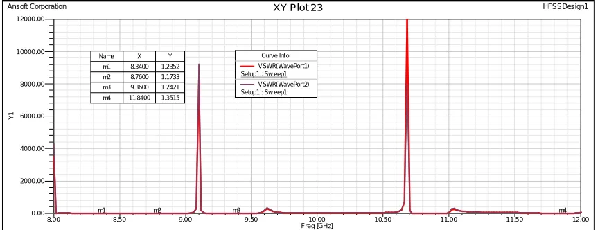
Figure7: VSWR plot for the proposed design 1
Figure8: Transmission spectra (S11 and S21 parameters) after the parametric variations of the geometry of SRR in design
1
Figure 9: VSWR plot for the optimized version of design 1
8.00 8.50 9.00 9.50 10.00 10.50 11.00 11.50 12.00
Freq [GHz] 0.00 2000.00 4000.00 6000.00 8000.00 10000.00 12000.00 Y 1
Ansoft Corporation XY Plot 23 HFSSDesign1
m1 m2 m3 m4
Curve Inf o V SWR(WavePort1) Setup1 : Sw eep1
V SWR(WavePort2) Setup1 : Sw eep1
Name X Y
m1 8.3400 1.2352 m2 8.7600 1.1733 m3 9.3600 1.2421 m4 11.8400 1.3515
8.00 8.50 9.00 9.50 10.00 10.50 11.00 11.50 12.00
Freq [GHz] -45.00 -40.00 -35.00 -30.00 -25.00 -20.00 -15.00 -10.00 -5.00 0.00 Y 1
Ansoft Corporation XY Plot 32 HFSSDesign1
m1
m 2
m3
m 4
m 5
l_outer=4 mm, w _outer=6 mm, h=1 2 cm, SRR in center
Curve Info
dB(S(WavePort1,WavePort1)) Setup1 : Sw eep1
dB(S(WavePort2,WavePort1)) Setup1 : Sw eep1
Name X Y
m1 8.2200 -19.1489
m2 8.7200 -14.0947
m3 9.4400 -40.3546
m4 10.2000 -11.8173
m5 10.9200 -32.0016
8.00 8.50 9.00 9.50 10.00 10.50 11.00 11.50 12.00
Freq [GHz] 0.00 500.00 1000.00 1500.00 2000.00 2500.00 3000.00 Y 1
Ansoft Corporation XY Plot 49 HFSSDesign1
m 1 m 2 m 3 m 4 m5
Curve Info VSWR(WavePort1) Setup1 : Sw eep1
VSWR(WavePort2) Setup1 : Sw eep1
Name X Y
Results
f (GHz)
RL
(dB)
Bandwidth
(MHz)
VSWR
Band1
8.22
-19.15
308
1.25
Band2
8.72
-14.1
451
1.49
Band3
9.44
-40.35
540
1.01
Band4
10.2
-11.42
510
1.68
Table 1: Results of return loss, bandwidth & VSWR at the operating frequencies of Design 1
Result Analysis: Figure 6 shows the S-parameter response for waveguide loaded with SRR in the central portion along the guiding axis, which demonstrates multi bands at 8.34 GHz, 8.76 GHz, 9.36 GHz and 11.84 GHz frequencies of X-band. As illustrated, return losses are above -10 dB and narrowband operations have been achieved. The VSWR are found to be in between 1 to 2 for all the operating frequencies. After parametric variations of the design values of length and width of SRR, S-parameter response of optimized design is analyzed shown in figure 8. This optimized design provides better responses in terms of return loss and bandwidths.
Figure10: Design 2- Model of unit cell waveguide loaded with SRR as MNG Metamaterial at load end side
-35.00 -30.00 -25.00 -20.00 -15.00 -10.00 -5.00 0.00
Y
1
Ansoft Corporation XY Plot 6 HFSSDesign1
m 1
m2
m 3 m 4
m 5
m 6 Curve Inf o
dB(S(WavePort1,WavePort1)) Setup1 : Sw eep1
Name X Y
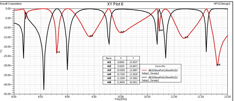
m1 8.8000 -23.4037
m2 9.4200 -14.8471
m3 10.0000 -12.6897
Figure12: VSWR plot for the proposed design 2
Results f
(GHz) Return Loss (dB) Bandwidth (MHz) VSWR
Band1 8.88 -23.43 87 1.15
Band2 9.42 -14.84 260 1.42
Band3 10.0 -12.65 260 1.59
Band4 11.2 -15.56 330 1.37
Band5 11.8 -30.06 480 1.07
Table 2: Results of return loss, bandwidth & VSWR at the operating frequencies of Design 2
Result Analysis: Figure 11 shows the S-parameter response for the waveguide loaded with SRR at the load end side. This provides the multi band response at the 8.88 GHz, 9.42 GHz, 10 GHz and 11.2 GHz. The VSWR are found to be in between 1 to 2 for all the operating frequencies. As illustrated, total resonating frequencies increases compared to the design1 which gives better options to tune the center frequency for applications operational in X band.
IV.CONCLUSION AND FUTURE WORK
It is demonstrated that the X-band circular waveguide loaded with split ring resonator exhibits the multi band operation property, which provides effectiveness for various satellite & wireless communication systems. The basic properties such as insertion & return loss, backward wave propagation & field distribution of circular waveguides filled with spit-ring-resonator based MNG Metamaterial are investigated experimentally and numerically. MTM based microwave circuits are presumed to be more compact than the conventional, so it is preferred to reduce the size of circular waveguide by loading it with metamaterials and with the design of the array of SRRs filled in waveguide, the improvements in results of return loss, bandwidth and compactness can be realized.
REFERENCES
1. R. Marques, J. Martel, F. Mesa, and F. Medina, ‘Left-handed-media simulation and transmission of EM waves in subwavelength split-ring-resonator-loaded metallic waveguides,’ Phys. Rev. Lett. , Oct. 2002.
2. Ziolkowski, R. W., ‘Design, fabrication, and testing of double negatie metamaterials,’ IEEE Transactions on Antennas and Wireless Propagation’, Vol. 51, No. 7, 2003
3. Silvia Harbar, Juraj Bartolic, Zvonimir Sipus, ‘Waveguide Miniaturization Using Uniaxial Negative Permeability Metamaterial’, IEEE Transactions On Antennas And Propagation, Vol. 53, No. 1, January 2005.
8.00 9.00 10.00 11.00 12.00 13.00
Freq [GHz] 0.00 100.00 200.00 300.00 400.00 500.00 600.00 700.00 Y 1
Ansoft Corporation XY Plot 10 HFSSDesign1
m1 m2 m3 m4 m5 m6
Curve Inf o
VSWR(WavePort1) Setup1 : Sw eep1
VSWR(WavePort2) Setup1 : Sw eep1
Name X Y
m1 8.8000 1.1447
m2 9.4200 1.4224
m3 10.0000 1.5914
m4 10.7200 1.6163
m5 11.2000 1.3780
4. K. Aydin, M. kafesaki, ‘Investigation of magnetic resonances for different split-ring resonator parameters and designs’, New Journal of Physics 7, 2005.
5. V. Veselago. ,’The electrodynamics of substances with simultaneously negative values of ε and μ,’ Soviet Physics Uspekhi, vol. 10, no. 4, pp.
509–514, Jan., Feb. 1968.
6. G. I. Eleftheriades, K. G. Balmain, ‘Negative-refraction metamaterials’, IEEE PRESS, 2005.
7. C. Caloz, T. itoh, ‘Electromagnetic metamaterials: Transmission line theory and microwave applications’, John Wiley & Sons, 2006.
8. M. Jalali, T. Sedghi, Y. Zehforoosh, ‘Miniaturization of Waveguides Dual Band Antenna Using TSRR-WS Metamaterials’, IEEE Vol. 1, No. 5 December, 2009.
9. Ilya V. Shadrivov, Andrey A. Sukhorukov, and Yuri S. Kivshar, ‘Guided modes in Negative refractive index wave guides’, Phy. Rev. E, Volume 67, 2003.
10. S. Kshetrimayum, Lei Zhu, ‘Novel Architecture for Waveguide Based Metamaterials’, Indian Institute of Science, 2000. 11. Jeffrey R. Clark, ‘Double Negative Metamaterials in Dielectric Waveguide Configurations’, 2006.
12. J.D. Baena1, R. Marqués1, ‘Experimental results on Metamaterial simulation using SRR-loaded wave guides’, 2000.
BIOGRAPHY
Zalak Patelhas pursued her B.E Electronics and Communication from Charotar Institute of Technology & Engineering, change. (Gujarat University) .She has pursued herM.Tech in communication Systems engineering from Charusat University, Changa. She has research work in the area of microwave engineering, especially in metamaterials inspired microwave circuits. She is currently working as an Assistant Professor at IndusInstitute of Technology, INDUS University. She has teaching experience of 5 years.
Miloni Ganatra has pursued her B.E Electronics and Communication from Ahmadabad Institute of Technology, Ahmadabad (Gujarat University). Shehas pursued her M.Tech. in VLSI Design from Nirma University. She iscurrently working as an Assistant Professor at Indus Institute of Technology,INDUS University. She has teaching experience of 5 years.